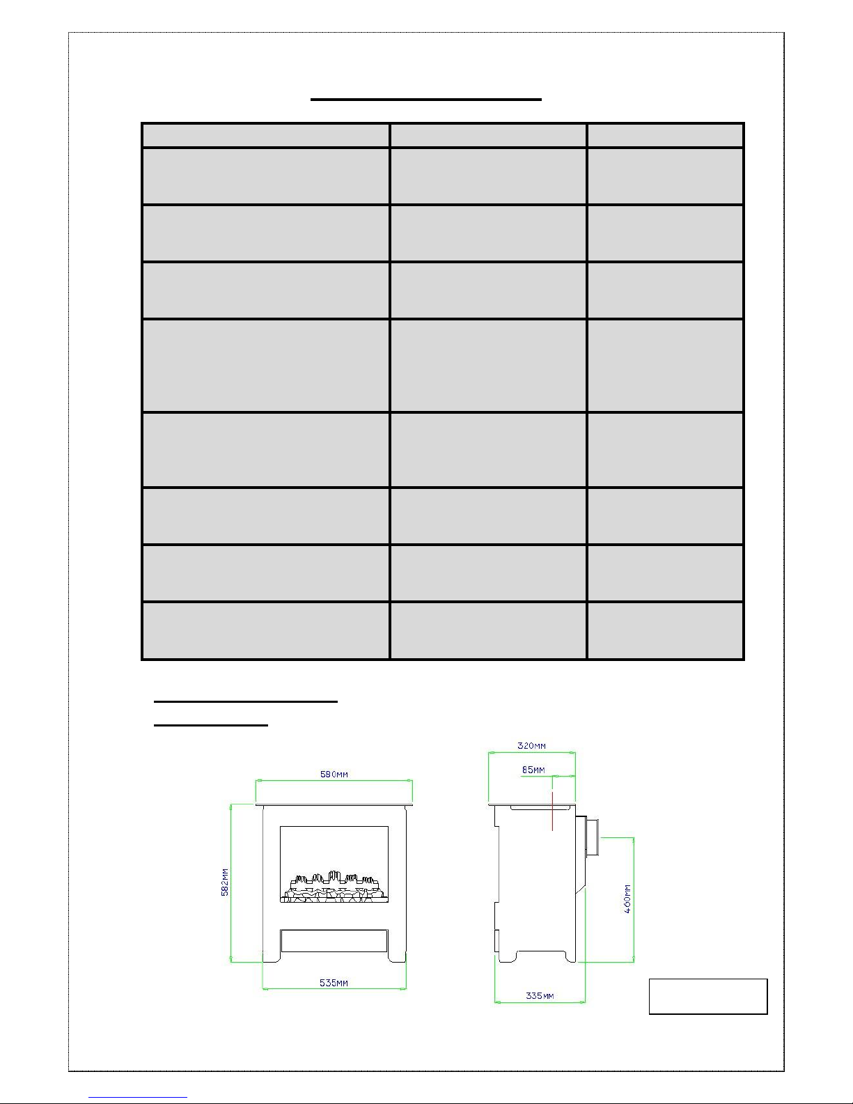
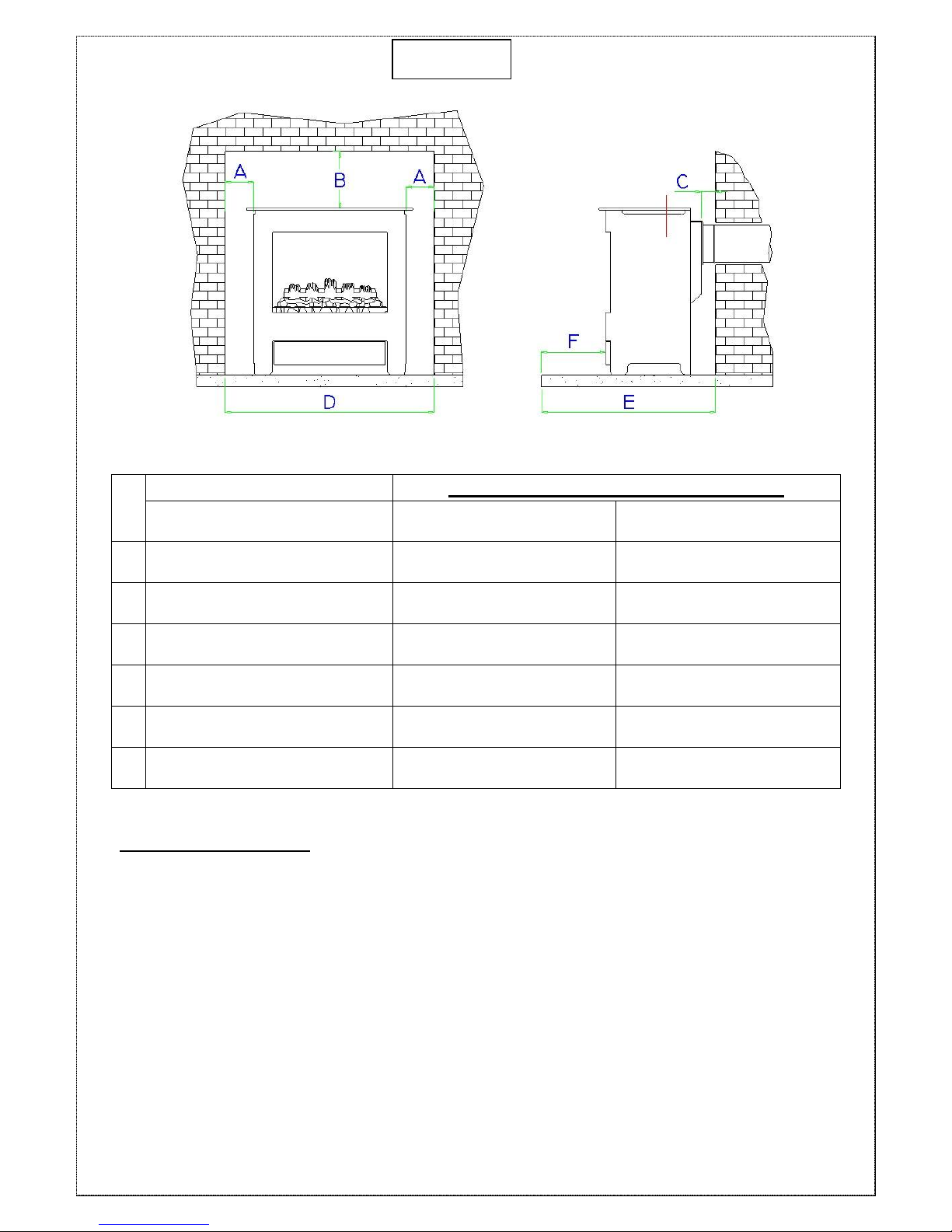
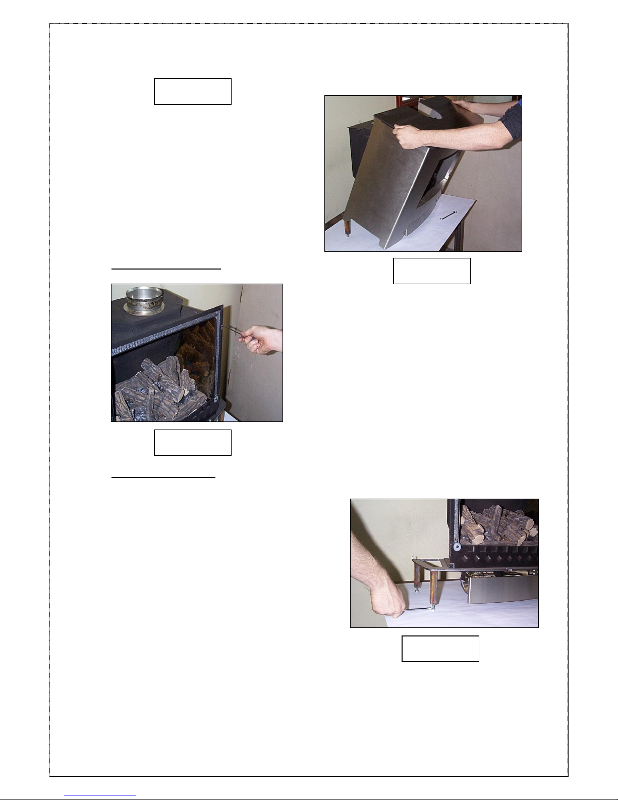
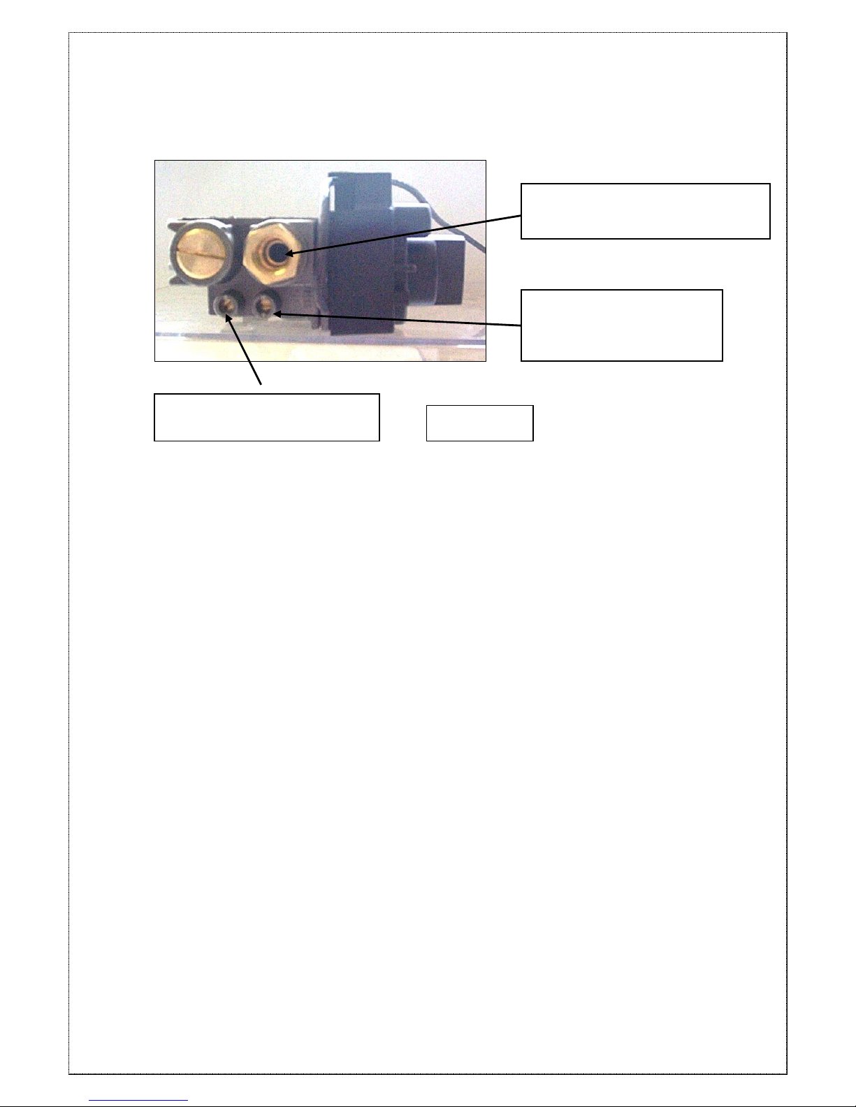
HS GAS Verona 6 User guide

Issue F: 18/02/14
VERONA
GAS STOVE
Installation and Servicing Instructions
Please leave this instruction booklet with the user after the
installation is complete. Leave the system ready for operation and
instruct the user in the correct use of the appliance and operation
of its controls.
Please refer to the appliance data plate for the specific model type.

Issue F: 18/02/14
2
Contents
TECHNICAL DATA ....................................... 3
STOVE DIMENSIONS............................................................................................3
NSTALLING THE APPLIANCE..................... 4
PRE-INSTALLATION NOTES .......................................................................................4
FLUE ARRANGEMENT ................................................................................................6
ADDITIONAL AIR VENTING (GB ONLY).....................................................................6
REMOVING THE STOVE BODY....................................................................................6
Removing the Glass.........................................................................................7
Levelling the Stove...........................................................................................7
GAS SUPPLY CONNECTIONS.....................................................................................8
TESTING SUPPLY PRESSURE ....................................................................................8
INSTALLATION OF THE FIRE-BED INTO
THE STOVE ................................................ 10
FIRE-BED ARRANGEMENT..............................................................................10
Section A - Fitting the ‘Coal Effect’ Ceramic Matrices..........................10
Fitting the Loose Ceramic Coals ................................................................11
Section B - Fitting the Log Effect Ceramic Matrices.............................13
Fitting the Loose Ceramic Logs..................................................................14
RE-ASSEMBLING THE STOVE..................................................................................16
TEST FOR SPILLAGE................................................................................................17
SPILLAGE MONITORING SYSTEM.............................................................................17
OPERATING THE APPLIANCE...................................................................................18
FITTING THE REMOTE CONTROL (OPTIONAL).........................................................18
Fitting the Motor to the Valve ......................................................................18
Attaching the Remote Control Receiver Box ..........................................19
SERVICING INSTRUCTIONS ..................... 20
PLEASE READ THESE INSTRUCTIONS CAREFULLY
It is important that your stove is correctly installed as HS GAS cannot
accept responsibility for any fault arising through incorrect installation.

Issue F: 18/02/14
3
TECHNICAL DATA
NATURAL GAS
LPG
Nominal Gas Pressure
20mBar
37mBar
Supply Gas Type/Category
G20/I2H
G31/I3P
Jet Type/Size
82/380
92/190
Heat Input (Gross)
Full
Low
6.5kW
4.2kW
6.4 kW
3.7 kW
Gas Flow Rate (m3/h)
Full
0.62 m3/h
0.236 m3/h
NOx Class
3
5
Efficiency Class
2
2
Countries of Destination
GB & IE Only
GB & IE Only
STOVE DIMENSIONS
VERONA 6:
Diagram 1a

Issue F: 18/02/14
4
NSTALLING THE APPLIANCE
Pre-Installation Notes
1. Check the stove data plate to establish the gas type required. The data
plate can be found on a chain at the top left rear corner of the stove.
Before installation check that the local distribution conditions, nature of
the gas and pressure, and adjustment of the application are
compatible.
2. A GAS SAFE REGISTERED INSTALLER or equally recognised
competent person must fit the appliance. That person is legally
responsible for the safe installation of the appliance with due regard to
all relevant local and national building regulations.
3. All outer surfaces of the stove excepting the gas control knobs are
defined as working surfaces.
4. Installation site
Any installation area previously used for a solid fuel fire or stove would
probably be deemed suitable for the appliance.
5. The stove must not be installed onto a combustible wall. Any
combustible materials must be removed from behind the appliance.
6. The appliance must be sited on a non-combustible hearth of minimum
12mm thickness.
7. The hearth should be edged or raised to prevent combustible floor
finishes (e.g. Carpet) from being laid too close to the appliance.
8. Opening clearances
For the relevant clearance distances when installing the appliance in
an opening see diagram 2 below:

Issue F: 18/02/14
5
IMPORTANT NOTE! Adequate clearance must be given between the
appliance and the walls so that a satisfactory spillage test can be performed
as detailed on page 16.
MINIMUM CLEARANCE DISTANCES TO:
DIMENSION DESCRIPTION
COMBUSTIBLE
MATERIAL
NON-COMBUSTIBLE
MATERIAL
A
Edge of stove top
to wall
100mm
50mm
B
Top of stove to underside
of opening
300mm
200mm
C
Rear of stove
to wall
N/A
50mm
D
Minimum fireplace
opening/Hearth dimension
780mm
730mm
E
Minimum hearth
depth
435mm
435mm
F
Minimum distance for hearth
to extend in front of stove
50mm
50mm
Diagram 2

Issue F: 18/02/14
6
Flue Arrangement
The GAS SAFE REGISTERED ENGINEER commissioned to install this
appliance is wholly responsible for deciding the suitability of any flue
arrangement to operate in conjunction with this gas appliance.
The chimney or flue system that is to be fitted to the Verona gas stove must
comply with the current rules in force.
(The Verona range of stoves is also suitable for other specific class 2
installation arrangements: pre-cast flues, ridge-vent flues and pre-cast
chimney block and with the relevant adaption, the appliance will operate in a
closure plate type system.)
It is suggested to run flue pipe at least 615mm vertically from the unit before
there are any changes in direction of the flue system. Wherever possible
horizontal runs of the flue system should be avoided.
The flue must have a minimum of 2.6 meters of vertical height measured
from the top of the stove to the bottom of the terminal outlet. Please note for
rear flue appliances it is recommended that the vertical flue run be established
as soon as is practical from the rear flue exit. (Caution should be taken
locating the exit of the flue as explained in ‘The Building Regulations -
Document J’.)
Before commencing any installation work the installing engineer must check
that the flue is free from all blockages, the chimney should be given a
precautionary clean, and finally the chimney should be smoke tested to
ensure soundness. Additionally any flue dampers must be permanently fixed
open or removed altogether.
Additional Air Venting (GB Only)
The supply gas heat input into the appliance is nominally less that 7kw,
therefore under the directives of the current gas safety and use regulations
(1995) no additional air vents are required in the room the appliance is
situated.
Removing the Stove Body
First completely remove the 2 securing
bolts that are located behind the valve
cover plate by using a 10mm spanner,
as shown in Diagram 3. Make sure
that the 2 rear fixings (Diagram 18 –
Page 16) are loose.

Issue F: 18/02/14
7
Gently slide the stove forward and lift
clear of the stove cartridge (Diagram 4).
Removing the Glass
The glass is held in place by 4 fixing clips,
2 at the top and 2 at the bottom. Slightly
slacken the lower two fixing screws with a
flat blade screwdriver (There is no need to
fully remove the screws). Holding the
glass with one hand, slacken off the top 2
fixing screws (Diagram 5) until the clips
have moved away from the glass panel.
The glass panel can then be lifted out.
Levelling the Stove
To achieve the optimum operating results the
stove should now be levelled with its
surroundings. This is carried out by
increasing or decreasing the length of the
levelling bolts located at the foot of each of
the stove legs, shown in diagram 6.
Diagram 3
Diagram 4
Diagram 5
Diagram 6

Issue F: 18/02/14
8
Gas Supply Connections
The appliance is supplied with a 8mm Bundy pipe and a 8mm compression
elbow to allow easy connection to the mains gas supply. This supply gas pipe
should incorporate a gas service isolation tap that is situated within 1 metre of
the application.
Diagram 7 shows the 8mm Bundy
pipe being fitted to the gas inlet
on the valve. The compression
joint is tightened with a 12mm
open-ended spanner.
Testing Supply Pressure
1. Gas pressure at the appliance is measured via the rearward test nipple
(Test nipple ‘A’ in diagram 8) on the left-hand side of the control valve.
(Turning the screw approximately half a turn anti-clockwise with a small
flat-bladed screwdriver opens the test point.)
ALWAYS CLOSE TEST POINTS AFTER USE!
2. The gas pressure at the appliance is measured with the appliance running
at full rate. (For information on how to achieve ‘full rate’ read, ‘Adjusting
between High and Low Output Settings’ in the ‘Lighting the Appliance’
section of the User Instructions.
Burner gas pressure should be:
Natural Gas @ 19mBars
LPG @ 36mBars
Diagram 7

Issue F: 18/02/14
9
3. The supply pressure coming into the appliance can also be checked by
using Test point ‘B’, shown in diagram 8.
Mains/Supply Pressure
Test Point
(Test Point ‘B’)
Gas Supply Connection
(8mm Compression Fitting)
Burner Pressure Test Point
(Test Point ‘A’)
Diagram 8

Issue F: 18/02/14
10
INSTALLATION OF THE FIRE-BED INTO
THE STOVE
IMPORTANT NOTE!!
CERAMIC COALS AND LOGS GET VERY HOT! NEVER ATTEMPT TO
HANDLE HOT COALS OR LOGS WITH BARE HANDS AND NEVER PLACE
HOT COALS OR LOGS ON OR NEAR COMBUSTIBLE SURFACES.
NO RESPONSIBILITY FOR ANY INJURY HOWEVER CAUSED
WHILST HANDLING HOT COALS, LOGS OR CERAMICS CAN BE
ACCEPTED BY HS GAS.
FIRE-BED ARRANGEMENT
This appliance can be fitted with either ‘coal effect’ or ‘log effect’ ceramics.
If you are fitting ‘Coal Effect’ ceramics please follow the instructions set out in
‘Section A – Fitting the Coal Effect Ceramic Matrices’ (Page 10).
If you are fitting ‘Log Effect’ ceramics please skip ‘Section A’ and follow the
instructions set out in ‘Section B – Fitting the Log Effect Ceramic Matrices’ (Page
13).
Section A - Fitting the ‘Coal Effect’ Ceramic Matrices
NATURAL GAS:The fire-bed is constructed of 3 ceramic matrices, 4 small
coals, 10 medium coals and 4 large ‘diamond shaped’ coals.
LPG: The fire-bed is constructed of 3 ceramic matrices, 10 small coals, 4
medium coals and 4 large ‘diamond shaped’ coals.
1. Place the rear ceramic matrix into
the fire. The ceramic should sit on the
burner tray top and be placed so that it
touches the back of the firebox (As
shown in diagram A9).
2. Place the middle ceramic matrix into the fire
so that the flat surface sits on the burner tray.
Push the middle ceramic back until it rests
against the rear ceramic shown in diagram
A10.
Note!
Make sure that the middle ceramic does not
block any of the burner tray slots.
Diagram A9
Diagram A10

Issue F: 18/02/14
11
3. Place the front ceramic matrix into
the fire so that it sits between the middle
ceramic matrix and the 2 front tray
supports (Steel brackets at the front of
the tray) shown in diagram A11.
Fitting the Loose Ceramic Coals
4. The first row of coals consists of 4
small coals and 4 large coals. The first
row of coals are placed so that they sit on
top of the front and middle ceramic
matrices.
Starting with a large ‘diamond shaped’
coal, place the front of the coal on top of
the left hand support leg of the front
ceramic. The back of the coal should rest
on the middle ceramic. Then take a small
coal and place the front of it in the first left
notch in the front ceramic, the back of the
coal resting on the
centre ceramic.
Continue this process, alternating the
coal size until all the 8 coals are placed
as shown in Diagram A12.
Note!
Make sure that the coals do not fall down between the front and middle
matrices.
A gap must be left between the coals to allow the flames to pass through.
5. The second row of coals
consists of 4 medium sized coals.
They are placed between the large
coals so that they sit on the middle
ceramic, shown in Diagram A13.
Note!
The coals must not block the
gap between the middle and
rear ceramic matrices.
Diagram A11
Diagram A13
Diagram A12

Issue F: 18/02/14
12
Diagram A14
6. The third row of coals
consists of 6 medium sized
coals (6 small coals for LPG
stoves). The coals are placed
so that they sit on top of the
last row of coals and into the
notches on the rear ceramic
matrix, shown in Diagram
A14.
Note!
Gaps must be left between
the coals for the flames to
pass through.
7. The fire-bed should now be completed. The stove should be lit and the
flame picture checked with the glass panel fixed securely in place. Any
adjustments to the flame picture can then be made as required.

Issue F: 18/02/14
13
Diagram B10
Section B - Fitting the Log Effect Ceramic Matrices
The fire-bed is constructed of 3 ceramic matrices and 6 loose logs.
A. Place the rear ceramic matrix
into the fire as shown in diagram
B9.
The ceramic should sit on the
burner tray top and be placed so
that it touches the back of the
firebox.
B. Place the middle ceramic matrix
into the fire so that the flat surface
sits on the burner tray. Push the
middle ceramic back until it rests
against the rear ceramic shown in
diagram B10.
Note!
Make sure that the middle ceramic
does not block any of the burner
tray slots.
C. Place the front ceramic matrix
into the fire so that it sits between
the middle ceramic matrix and the
2 front tray supports (Steel
brackets at the front of the tray)
shown in diagram B11.
Diagram B9
Diagram B11

Issue F: 18/02/14
14
Diagram B14
Fitting the Loose Ceramic Logs
D. Starting with the Y-
shaped log, place at the
angle shown in diagram
B12. The bottom of the log
should sit in the cut-out on
the front ceramic matrix, with
the flat underside of it resting
on the flat area on the
middle matrix. Of the longer
2 branches, the tip of the
right hand branch should
rest in the left hand cut-out
on the rear ceramic.
E. The second log has two short
branches coming from it. It sits in the
furthest left cut-out on the front
ceramic and rests in the groove on
the centre ceramic, shown in
diagram B13.
F. The third log to be placed is the
thin ‘twig’. The ‘Twig’ is placed in the
cut-out between the first two logs.
The small branch on the twig should
sit at an angle into the cut-out on the
front ceramic, so stopping the twig
from falling between the front and
centre ceramic. The top of the twig
should rest on the large log as
shown in diagram B14. (Make sure
that the position of the ‘Twig’ does
not block any of the burner ports)
Diagram B13
Diagram B12

Issue F: 18/02/14
15
G. The fourth log is the shorter
of the two straight logs. The log
should rest on the middle
ceramic on the flat section to
the right of the large log. The
top of the log should rest in the
groove on the rear ceramic, as
shown in diagram B15.
H. The fifth log is the longer
of the two straight logs, the
top of this should sit in the
final groove on the rear
ceramic in between the
large log and the shorter
straight log. The log should
also rest on the join
between the other 2 placed
logs as shown in diagram
B16.
I. The sixth and final log
has a single branch
coming from it and one
end is shaped to be
parallel with the mirrored
side. It should sit on the
flat surface on the centre
ceramic as shown in
diagram B17.
J. The fire-bed should now be completed. The stove should be lit and the
flame picture checked with the glass panel fixed securely in place. Any
adjustments to the flame picture can then be made as required.
Diagram B15
Diagram B16
Diagram B17

Issue F: 18/02/14
16
Re-Assembling the Stove
When the desired flame picture has been achieved, the stove body should be
reassembled.
The stove body can be slid back into
place, making sure that the pins on the
rear of the body locate into the 2
securing brackets at the back of the
base, shown in diagram 18.
The two front fixing bolts can then be
replaced and tightened to fix the body in
place (Shown in Diagram 3 –Page 7).
Diagram 18

Issue F: 18/02/14
17
TEST FOR SPILLAGE
A Spillage test MUST be carried out before the appliance is left with the
customer.
Carry out the test by first closing all doors and windows in the room containing
the fire.
Ensure that the fire is burning at full rate for a minimum of 5 minutes.
Using a smoke match –run along the edge of the draught diverter, both sides of
the TTB Bracket as shown in diagram 17.
Most of the smoke should be drawn into the
draught diverter. If not, leave the stove running
at full rate for a further 10 minutes and repeat
the test. I
If there is a fan in an adjoining room the
spillage test must be repeated with the fan
running and all connecting doors between the
fire and fan open.
If there are still problems the chimney/flue or
ventilation may require attention. The stove
should not be used until the fault is rectified.
SPILLAGE MONITORING SYSTEM
This appliance is fitted with an ‘oxygen depletion system’ (ODS) pilot
assembly which will monitor any spillage from the appliance.
The system MUST NOT be adjusted or changed by the installer.
Replacement systems must be obtained from HS Gas; no other pilot
assembly must be substituted in its place.
The appliance is also fitted with a thermostatic switch (TTB). This switch is
located in the draught diverter and shuts off the gas supply should the flue
lack sufficient flow to prevent flue gas spillage. The TTB MUST NOT be
removed or ‘bridged out’ for any reason and only genuine HS Gas
replacements should be used. Nuisance shut down may occur if the stove is
not installed in accordance with the clearance distances set out in page 5.
Diagram 17

Issue F: 18/02/14
18
Diagram 21
Operating the Appliance
FULL OPERATING INSTRUCTIONS ARE GIVEN IN THE USER INSTRUCTIONS.
Fitting the Remote Control (Optional)
Fitting the Motor to the
Valve
Un-screw the cover retaining screw with
a small Philips screwdriver (Shown in
diagram 20). Prise off the cover at the
snap connection with a small flat-bladed
screwdriver located on the right hand
side of the valve.
Turn the main burner control
knob (Knob ‘B’ – diagram 21)
fully anti-clockwise until the
end stop is reached.
Fit the motor as shown in diagram
22, making sure that the motor sits
on the locating pin.
Replace the valve cover and tighten
the Philips headed screw. (Do not
overtighten the screw as this may
effect the operation of the control).
Make sure that the snap connector
has located properly. When fitted
correctly, the valve cover holds the
motor in the correct position.
Diagram 20
Diagram 22
Knob B
Motor

Issue F: 18/02/14
19
Attaching the Remote Control Receiver Box
The control lead is then attached to the receiver box using the plastic
connector and to the valve motor by the two spade terminals.
The Remote Control Receiver Box is powered by 4 x AA batteries (supplied).
The batteries are fitted by sliding the cover off the receiver box the orientation
of the batteries shown on the diagram in the box.
Fit the 9-volt battery to the remote control handset.
Test that the remote control system is working by pressing the increase and
decrease buttons on the handset.
If the system is working correctly, the receiver box can be sited. The ideal
position for the receiver box being on the hearth, at the back of the stove.
The remote control system is ultra-sonic and hence the receiver box does not
have to be in line of sight of the remote handset.
WARNING!
The receiver box should not be sited anywhere that the temperature will be
greater than 50Celsius. High temperatures will shorten the battery life and
may cause the remote control receiver to stop operating.

Issue F: 18/02/14
20
SERVICING INSTRUCTIONS
It must be understood that any recommendations made here are in addition to
the standard servicing procedures used by the servicing engineer.
1. A GAS SAFE registered fitter using only original HS GAS parts should
carry out servicing
2. Remove the stove body and glass as described on Page 7 (Removing
the Stove Body).
3. Carefully lift-off the ceramic coals/logs and remove the 3 ceramic
matrices.
4. Using a soft brush, clean away any lint or light carbon soot deposits out
of the gas ports on the burner top plate.
5. Check the TTB bracket inside the draught diverter for blockage and
clean as necessary.
6. Replace the ceramic matrices and loose coals/logs as per the
arrangement instructions (Page 10- Fire-bed Arrangement) using all re-
serviceable coals/logs and any new replacements. Replace the glass
and stove body as described on Page 16 (Re-assembling the Stove).
7. Check the gas operating pressure and pipe work for soundness, carry
out a spillage test and check the condition of the flue system.
Table of contents
Other HS GAS Stove manuals
Popular Stove manuals by other brands

Coleman
Coleman PEAK 1 3001 Series Instructions for use

Farmakom
Farmakom GULIVER user manual

Rommelsbacher
Rommelsbacher CT 3408/IN instruction manual

LA NORDICA
LA NORDICA Giulietta Instructions for installation, use and maintenance

Coleman
Coleman 9911-750 parts list

Harman Stove Company
Harman Stove Company P61A-2 owner's manual

Mendip Stoves
Mendip Stoves WOODLAND DS Operation and installation manual

GAS ONE
GAS ONE B-5400 Owner's Manual and Operating Instructions

HunterGas
HunterGas HUNTER HAWK 4 MKII Instructions for installation and servicing

Coleman
Coleman 5442 Series Instructions for use

Palazzetti
Palazzetti ECOFIRE HOTTY Instructions for use and maintenance

WANDERS
WANDERS Balsa 75 T quick start guide