lp-701 Rev. 000 Rel. 003 Date 6.29.20
9
Return Water Temperature Sensor
This sensor monitors VWH return water temperature (System
Return).
Temperature and Pressure Gauge
Allows the user to monitor system temperature and pressure.
Electrical eld connections with terminal strips
The electrical cover allows easy access to the clearly marked line
voltage and low voltage terminal strips to facilitate wiring the VWH.
Supplied Condensate Collection System with Clean Out
This VWH is a high eciency appliance and will produce condensate.
The condensate collection system has a oat switch which monitors
condensate level and prevents condensate from backing up into
the combustion system. Inside the collection system is a built in trap
which seals the combustion system from the connected drain. This
condensate should be neutralized to avoid damage to the drainage
system or piping.
Flow Protection
The ow switch is designed to protect the VWH during low ow
conditions. The VWH control also monitors ow through the heat
exchanger by monitoring the return and supply sensors and will
shut down the burner before overheating occurs. The ow switch
activates at 4 GPM for 400 - 1000 Models; 9 GPM for 1500 - 2000
Models.
0-10 Volt Input
Allows the installer to connect a BMS (Building Management
System) to control the VWH.
0-10 Volt Output A (Congured through Control System)
0-10 Volt Output A is congured through the VWH control system.
0-10 Volt Output A is related to one of the following values: VWH
power, cascade power, fan speed, alarm status, temperature setting
based on outdoor reset curve, ame, or pump.
0-10 Volt Output B (Congured through Control System)
0-10 Volt Output B is congured through the VWH control system,
and is related to one of the following values: VWH power, cascade
power, fan speed, alarm status, temperature setting based on
outdoor reset curve, or ame.
UL 353 Internal Low Water Cuto (LWCO)
The supplied internal Low Water Cuto in conjunction with the 928
control meets UL 353 requirements to function as a safety, locking
out the VWH when water level is inadequate for safe operation. See
Service Mode, this manual, to test LWCO function.
Flue Temperature Modulation
As an additional safety feature, if the ue temperature exceeds
200oF, the control will modulate the VWH down based on the
vent temperature, rather than the supply temperature. If the ue
temperature exceeds 210oF the control will lock out the VWH.
HTP Link
HTP Link allows the installer to connect the VWH to WiFi, providing
the user / installer with tools to remotely monitor the system,
optimize eciency, and aid in troubleshooting.
System Sensor (Optional)
This sensor is designed to be used in a cascade system. The
system pipe sensor measures the temperature of return water and
communicates with the control system to modulate the ring rate of
the connected VWHs.
NOTE: When using a system sensor, pipe insulation must be
wrapped around it to improve temperature measurement accuracy
and increase overall system eciency.
C. Optional Equipment
Optional equipment available from HTP (and Part #):
• System Sensor (7250P-324)
• Indirect Tank Sensor (7250P-325)
• High and Low Gas Pressure Switch Kit with Manual Reset
(500 Model [7550P-999], 650 - 2000 Models [7550P-988])
• 4” Stainless Steel Vent Termination Kit (V2000)
• 6” Stainless Steel Outside Termination Vent Kit (V3000)
• 8” Stainless Steel Elbow (7550P-067)
• 8” Stainless Steel to PVC / CPVC Vent Pipe Adapter (7550P-064)
• Mechanical Manual Reset High Temperature Limit (6300P-998)
• Alarm System Kit (to monitor any failure) (7350P-602)
• 928 PC Connection Kit (7450P-330)
• Condensate Neutralizer (7350P-611)
• Condensate Removal Pump (554200)
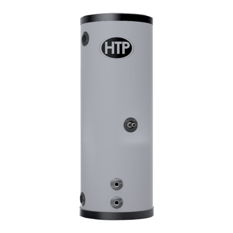
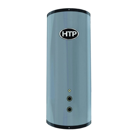
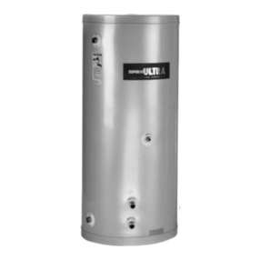
• Glass-Lined Storage Tanks (GL-80, GL-119, GL-175)
• Stainless Steel Storage Tank (SSU-80CB, SSU-119CB)
NOTE: When using an optional system sensor, pipe insulation must be
wrapped around it to improve temperature measurement accuracy
and increase overall system eciency.
Part 3 - Prepare the VWH
Remove all sides of the shipping crate to allow the VWH to be moved
into its installation location. The VWH is heavy. At least two individuals
and special equipment (pallet jack, forklift, etc.) are needed to properly
handle the VWH. If surface ooring is rough, take care not to damage
the VWH when moving it into position.
COLD WEATHER HANDLING - If the VWH has been stored in a very
cold location (BELOW 0oF) before installation, handle with care until
the components come to room temperature. Failure to do so could
result in damage to the VWH.
Carefully consider installation when determining VWH location.
Please read the entire manual before attempting installation. Failure
to properly take factors such as VWH venting, piping, condensate
removal, and wiring into account before installation could result in
wasted time, money, and possible property damage and personal
injury.
Figure 1 - Moving the ELX - 1500 - 2000 Models Shown
This VWH is certied for indoor use only as shipped. DO NOT INSTALL
OUTDOORS without an optional Outdoor Installation Kit. Follow the
instructions included with the optional Outdoor Installation Kit when
installing the VWH outdoors. Installing the VWH outdoors without an
optional Outdoor Installation Kit WILL VOID the warranty, and could
result in property damage, severe personal injury, or death.
A. Locating the VWH
Incorrect ambient conditions can lead to damage to the heating
system and put safe operation at risk. Ensure that the installation
location adheres to the information included in this manual. Failure
to do so could result in property damage, serious personal injury, or
death. Failure of the VWH or components due to incorrect operating
conditions IS NOT covered by product warranty.
