HTS VRS N70 User manual

VRS N70 Imaging Unit
2 Megapixel Network Camera Series
Quick Installation Guide
Version 1.0
November 2017

N70 Imaging Unit Quick Installation Guide
HTS Proprietary Page 2
Table of Contents
CHAPTER 1 SAFETY AND CERTIFICATIONS..........................................................3
1.1 Safety Instructions........................................................................................3
1.2 Disposal of Equipment..................................................................................4
CHAPTER 2 PRODUCT DESCRIPTION ..................................................................5
2.1 Overview ......................................................................................................5
2.2 Specifications................................................................................................6
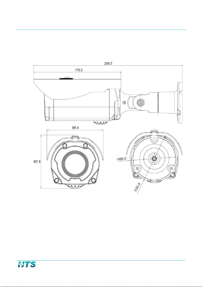
2.3 Unit Dimensions ...........................................................................................7
CHAPTER 3 INSTALLATION PREPARATION .........................................................8
3.1 Checking for Damage....................................................................................8
3.2 Unpacking the Unit.......................................................................................8
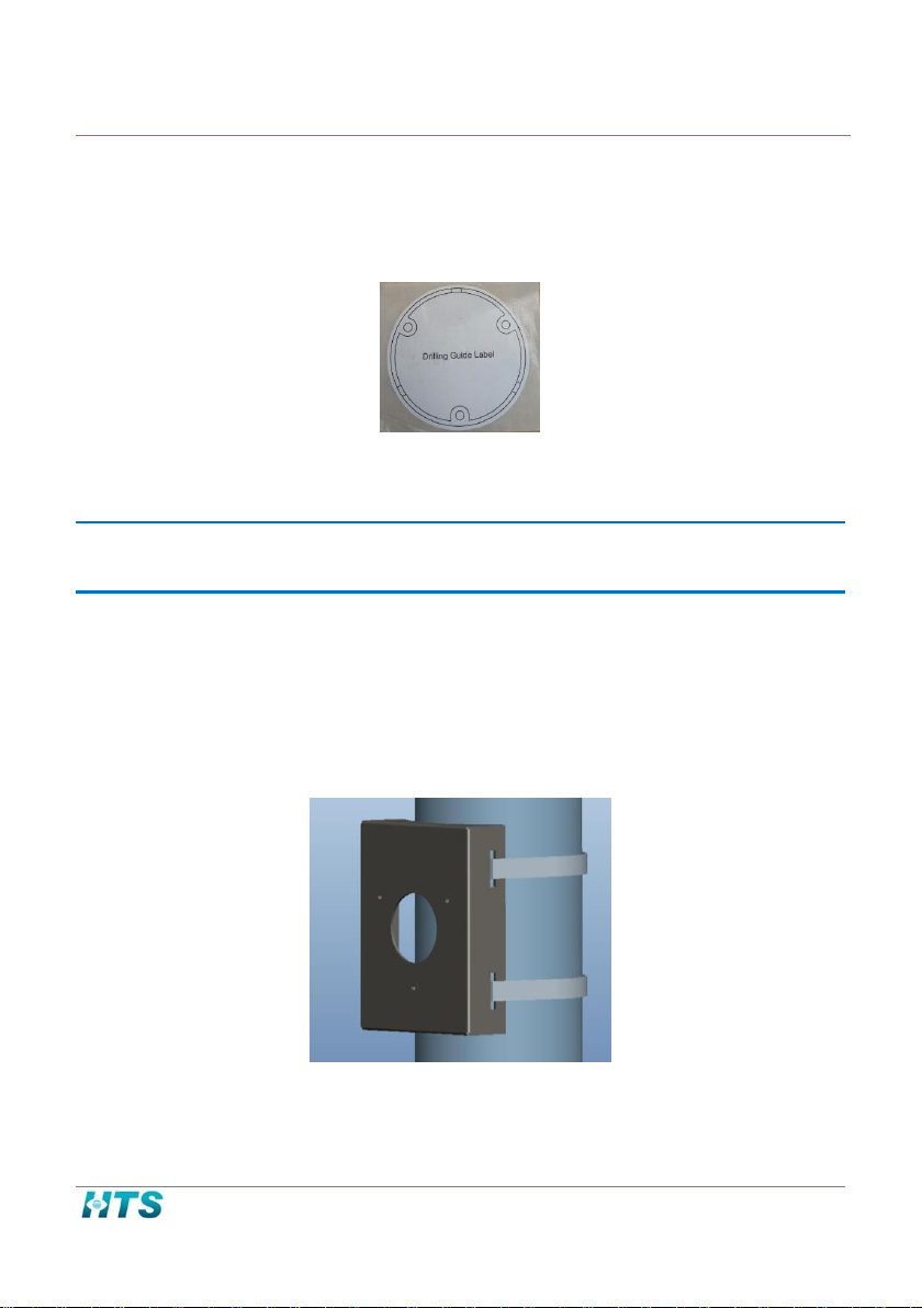
3.3 Pole Mount Adaptor Kit..............................................................................10
CHAPTER 4 INSTALLATION ...............................................................................11
4.1 Installation Tools ........................................................................................11
4.2 Cable Wiring Description............................................................................11
4.3 Mounting the N70 on a Wall ......................................................................15
4.4 Adjusting the Imaging Unit Position ...........................................................18
4.5 Mounting the N70 on a Pole ......................................................................19
4.6 Network Topology ......................................................................................21
4.7 Setting Focus and Zoom .............................................................................22
CHAPTER 5 IP CONFIGURATION .......................................................................23
5.1 Default IP Address ......................................................................................23
5.2 IP Configurator Utility.................................................................................23
5.2.1 Running IP Configurator from the Lane Controller ................................23

N70 Imaging Unit Quick Installation Guide
HTS Proprietary Page 3
Chapter 1 Safety and Certifications
NOTICE
Please read this guide thoroughly and save it for future use before attempting to connect or
operate this unit.
1.1 Safety Instructions
HAZARD: Please follow the safety instructions below. Failure to adhere to the
instructions could result in personal injury to the user.
This unit operates at 12VDC and using PoE+ only.
Installation and service should be performed only by qualified and
experienced technicians and comply with all local codes and rules in order
to maintain your warranty.
Wipe the imaging unit with a dry soft cloth. For tough stains, apply a small
quantity of diluted neutral detergent and wipe dry with a soft cloth.
Do not apply benzene, gasoline, or thinner to the imaging unit, which may
melt the surface of the unit or cause fogging in the lens.
Avoid aligning the lens to very bright objects (for example, light fixtures)
for long periods of time.
Avoid operating or storing the unit in the following locations:
oExtremely humid, dusty, or hot/cold environments
(recommended operating temperature: -30°C to +50°C)
oClose to sources of powerful radio or TV transmitters
oClose to fluorescent lamps or objects with reflections
oUnder unstable or flickering light sources
oFor eye safety –avoid looking directly to the LED`s illumination
beam

N70 Imaging Unit Quick Installation Guide
HTS Proprietary Page 4
1.2 Disposal of Equipment
WEEE (Waste Electrical and Electronic Equipment). Correct disposal of
this product (applicable in the European Union and other European
countries with separate collection systems). This product should be
disposed of, at the end of its useful life, as per applicable local laws,
regulations, and procedures.

N70 Imaging Unit Quick Installation Guide
HTS Proprietary Page 5
Chapter 2 Product Description
2.1 Overview
The N70 is a state-of-the-art, 2 megapixel imaging unit. It is supplied with the
following interfaces:
2 shielded copper pairs for power and I/O.
An Ethernet interface for transmission of images.
The Ethernet interface is also used by management software to
configure the imaging unit and provide power via PoE+.

N70 Imaging Unit Quick Installation Guide
HTS Proprietary Page 6
2.2 Specifications
Item
Specification
Sensor type
1/2.8” SONY STARVIS CMOS
Active Pixels
1945 x 1097 @30 fps
Lens
Digital Zoom x16
Effective Range
Standard: 3-17 meters,
Angle of View 54.0° (H) ~ 4.9° (V)
Video Compression
H.264
Protocol
TCP/IP
Housing –Mechanical / Electrical
Weight
1.2 Kg
Protection Level
Water/Dust proof IP66, Vandal IK10
Operating Temperature Range
-30°c ~ 50°c/ -20°F~122°F
Adjustment Angles
3 (up/down, right/left, Yaw)
Line In
12VDC (19.2W), PoE+ (23W).
Heating
Contains heater with thermostat control
Illumination
Spectrum
Infra-red (850nm or 730nm),
or white illumination
Quantity
32 LEDs
Safety and Certifications
CE Regulation
Yes
Manufacturing quality certification
ISO 9001-2008
Table 1: N70 Specifications

N70 Imaging Unit Quick Installation Guide
HTS Proprietary Page 7
2.3 Unit Dimensions
Note: All Dimensions are in mm

N70 Imaging Unit Quick Installation Guide
HTS Proprietary Page 8
Chapter 3 Installation Preparation
3.1 Checking for Damage
When first unpacking, please check if there is any visible damage to the unit
and its accessories. The protective materials used for the packaging should be
able to protect the unit from most forms of damage during transportation.
NOTE
Please contact HTS if the item or any of its accessories is damaged.
3.2 Unpacking the Unit
Open the N70 package and make sure that the contents match the order
form and the packing slip.
Check that the following items below are included in the package:
One N70 Imaging Unit
One printed Quick Installation Guide (this document)
Sunshield
Figure 1: Sunshield

N70 Imaging Unit Quick Installation Guide
HTS Proprietary Page 9
Pole mount Bracket and metal bands
Figure 2: Pole Mount Base
Mounting accessory kit
1 secure screw M5x8mm/ SUS/ Black, item (4) below
3 screws (M4x15) for mounting bracket, item (1) below
1 plastic washer, item (5) below
1 wrench 3mm tool (L key), item (2) below
Figure 3: Mounting Accessory Kit

N70 Imaging Unit Quick Installation Guide
HTS Proprietary Page 10
Placement sticker
Figure 4: Placement Sticker
NOTE
Please contact HTS if any of the items listed is missing.
3.3 Pole Mount Adaptor Kit
The pole mount adaptor supplied is with the N70. See attached figure below
showing the adaptor attached to a pole
Figure 5: Pole Mount Adaptor

N70 Imaging Unit Quick Installation Guide
HTS Proprietary Page 11
Chapter 4 Installation
4.1 Installation Tools
The following tools may be necessary to complete the installation:
Electric drill
Screwdrivers
Wire cutters
Set of hex keys (Allen wrenches)
4.2 Cable Wiring Description
HAZARD: All imaging unit installations should comply with your local electrical
safety rules.

N70 Imaging Unit Quick Installation Guide
HTS Proprietary Page 12
See the drawing with details on the connectors:
Figure 6: N70 connectors
Alarm_In
Speaker
Mic
Alarm_Out
12VDC
Ethernet

N70 Imaging Unit Quick Installation Guide
HTS Proprietary Page 13
See the attached table with details on the connectors:
Table 2: N70 Connectors
No.
Description and actual writing
Description
P5
RJ-45
Ethernet, RJ-45 10/100Mbps, PoE+
P6
DC Jack
Main Power, DC12V Input
P7
Normally_Closed
Alarm_output terminal, 3 pin
terminal
Common
Normally_Open
P8
MIC (Audio In)
Audio line input, 2 pin terminal
G (GND)
P9
SPK (Audio Out)
Audio line output, 2 pin terminal
G (GND)
P10
AI-P
Alarm input terminal, 2 pin terminal
N

N70 Imaging Unit Quick Installation Guide
HTS Proprietary Page 14
NOTE
If direct H/W trigger connection is required (from loom for example), connect the loop wires to
the Alarm_In pair
NOTE
If opening gate connection is required, connect the gate wires to the Alarm_Out wires
according to the specific gate logic (Normally Open/ Normally Closed)
NOTE
Network connectivity topology is defined later in this chapter.
WARNING: To avoid damage to the unit, connect it only to the
original supplied power supply.

N70 Imaging Unit Quick Installation Guide
HTS Proprietary Page 15
4.3 Mounting the N70 on a Wall
1. Before placing the unit on the wall, connect the sun shade
(supplied with the unit) to the unit, use 2 screws in the plastic bag:
Figure 7: Attaching sun shade to the unit
Note: adjust the sun shade position (slide it out from the unit) in
order to protect the unit front from sun glare, rain etc.
2. Once done, place the placement sticker on the wall:
Figure 8: Placement sticker

N70 Imaging Unit Quick Installation Guide
HTS Proprietary Page 16
3. Once the sticker is placed correctly, drill the 3 knock in plastic
anchors supplied with the unit to the wall.
4. Once done, place the unit in position verify the cable placed
correctly, there are two methods to placing the cables, see detailed
drawing below:
Figure 9: Attaching the N70 to the wall, cable position method 1
Figure 10: Attaching the N70 to the wall, cable position method 2

N70 Imaging Unit Quick Installation Guide
HTS Proprietary Page 17
5. Once done, place the unit in position and then lock in 3 self-tapping
screws to fasten the camera to the wall
Figure 11: Attaching the N70 to the wall
6. Once the unit is placed correctly, connect the wires as needed.

N70 Imaging Unit Quick Installation Guide
HTS Proprietary Page 18
4.4 Adjusting the Imaging Unit Position
Use the L key supplied with the unit; adjust all the axis screws on the
unit as described in the figure below.
Figure 12: N70 adjustment
NOTE
After completing the adjustments, tighten all screw in order to prevent the imaging unit from
moving.

N70 Imaging Unit Quick Installation Guide
HTS Proprietary Page 19
4.5 Mounting the N70 on a Pole
To mount the N70 on a pole:
1. Connect the sun shade as described above
2. Insert the two metal bands into the pole mount adaptor
Figure 13: Metal bands insertion
3. Use a screw driver and fasten the two metal bands
Figure 14: Metal bands fastening
NOTE
The N70 cables should be threaded through the bottom side of the N70 bracket.
Pole Mount
Adaptor
Metal bands

N70 Imaging Unit Quick Installation Guide
HTS Proprietary Page 20
4. Place the unit in position and fasten the three screws, as described
in the figure below:
Figure 15: fastening the unit to the Pole mount Adaptor
Table of contents
Other HTS Security Camera manuals