8/17
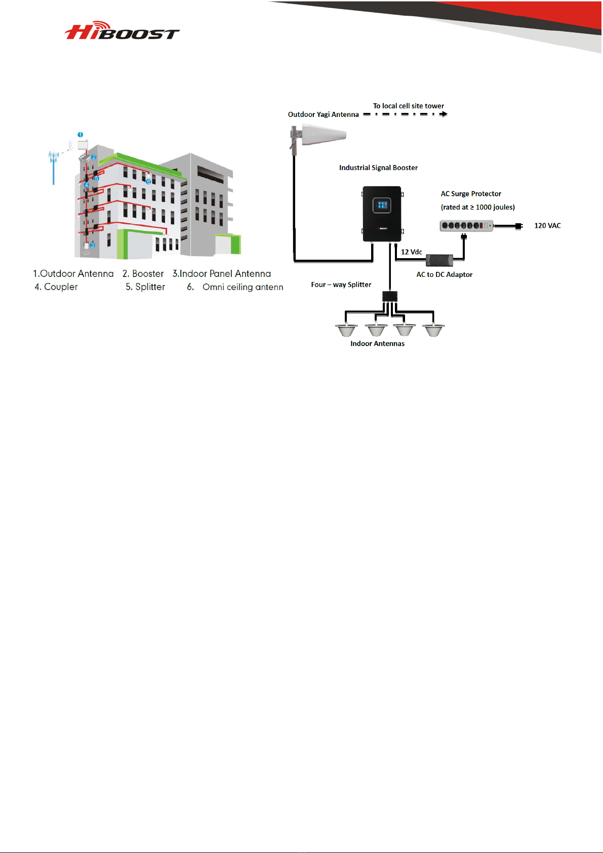
Booster Implementation and Testing
How to find the position with the strongest receiving signal?
The booster's main function is to improve weak RF signal inside a house, office or any other indoor
area. The receiving strength of the outdoor antenna and the strength of the signal reception outdoors
directly affect the efficiency of indoor coverage. That's why it's crucially important to install the
outdoor antenna in the point where signal reception is the strongest.
There is a recommended method for finding strongest receiving signal to use mobile phone to test
signal bars.
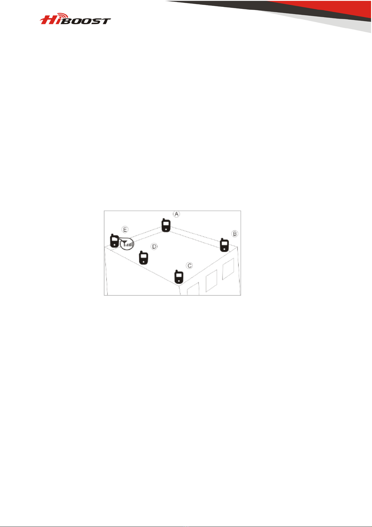
Mobile Phone Method
You can use telephone to test signal strength near the window or on the top of the building. The
number of bars on network indicator will define approximate strength of the received signal.
Normally the roof of the building is the best place to receive the strongest signal. As shown on the
graph below, you need to test the signal in points from A to E, and select a place with best signal
strength for outdoor installation. It is recommended to use mobile app that can display signal level,
since it is more accurate than checking signal bars.
More tips: Please try to pick up signal from cell towers that are not so busy, which can be
estimated by the population density in the area served by this tower. It’s also recommended to avoid
a cell tower near a supermarket, shopping mall, stadium and any other public place visited by many
people regularly. This will help on successful phone call connections or higher speed data services.
1.Install OutdoorAntenna
In most cases, the panel antenna is the best choice. You can also choose wide band YAGI antenna
as an option.
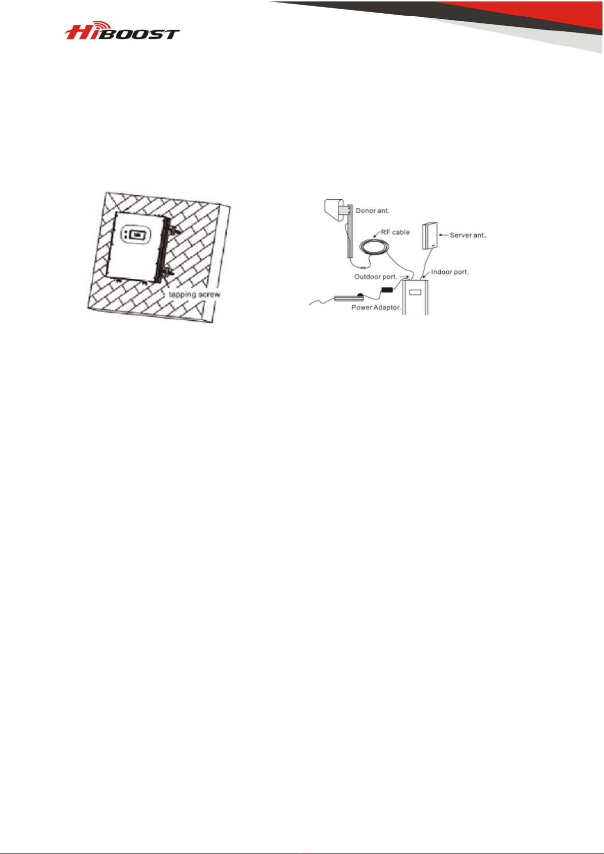
There are 2 types of installation: wall mount or pole mount.
Install outdoor panel antenna onto the wall for your reference:
Step1: Unscrew antenna from L-mounting bracket on antenna base with wrench. Step2: Mount
vertical plate of the L-bracket on the wall with supplied screws. Step3: Screw antenna back onto
horizontal plate.