9
Settings
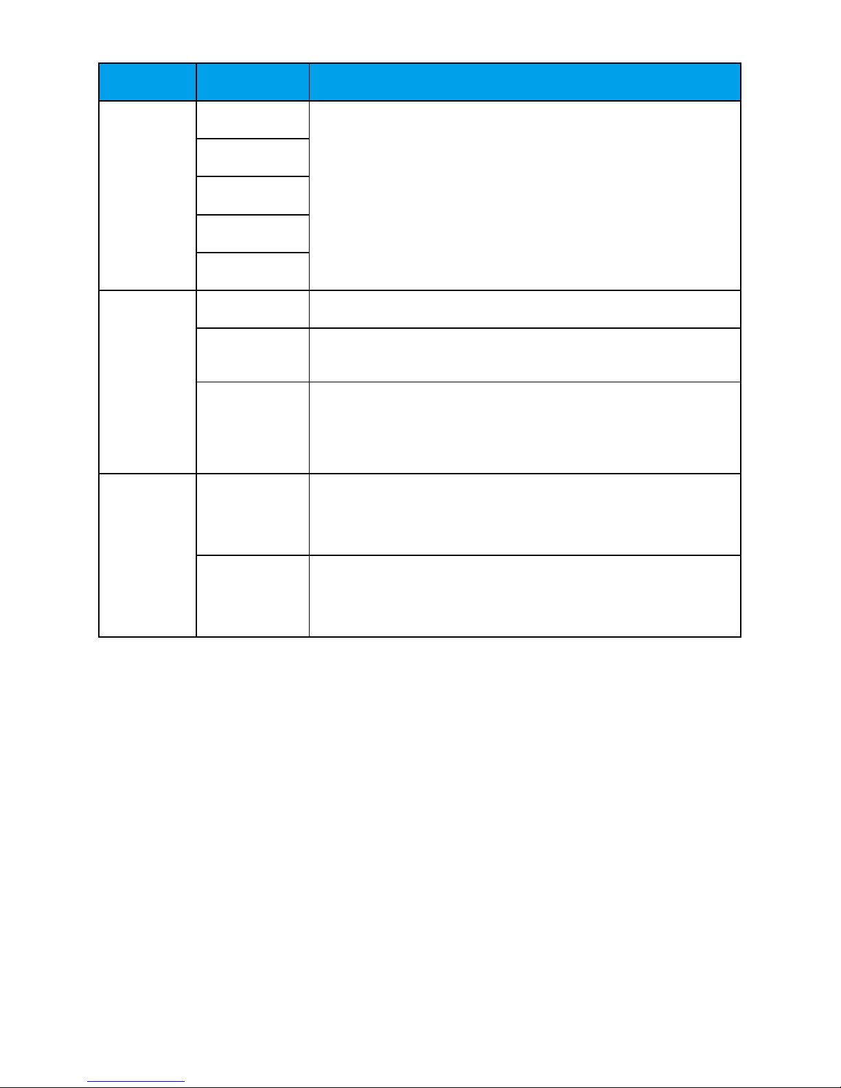
SELECT Mode Description
RC IR-REMOTE The camera forwards IR signals to a videoconferencing
endpoint and is controlled by the videoconferencing endpoint.
By default, RC is set to IR-REMOTE.
IR-LOCAL The camera is controlled by IR signals and stops forwarding
the signals to the videoconferencing endpoint.
RF-REMOTE The camera forwards RF signals to a videoconferencing
endpoint and is controlled by the videoconferencing endpoint.
RF-LOCAL The camera is controlled by RF signals and stops forwarding
the signals to the videoconferencing endpoint.
HD-MODE STANDARD The video is displayed in standard mode.
If you select this option and set VEDIO to 720p 60 fps, 1080p
30 fps, 1080i 60 fps, 1080p 60 fps, 4K2Kp 30 fps, and 4K2Kp
60 fps, the actual video format are 720p 59.94 fps, 1080p
29.97 fps, 1080i 59.94 fps, 1080p 59.94 fps, 4K2Kp 29.97
fps, and 4K2Kp 59.94 fps respectively.
By default, HD-MODE is set to STANDARD, which is
recommended.
FULL The video is displayed in full frame mode.
If you select this option, set VEDIO to 720p 60 fps, 1080p 30
fps, 1080i 60 fps, 1080p 60 fps, 4K2Kp 30 fps, or 4K2Kp 60
fps based on the site requirements.
VIDEO 4K2Kp 60 Select a video format.
Only a VPC800 with a 4K license supports this function.
4K2Kp 50
4K2Kp 30
4K2Kp 25
1080p 60 Select a video format.
1080p 50
1080i 60