manuals.online logo
Brands
  1. Home
  2. •
  3. Brands
  4. •
  5. Huawei
  6. •
  7. Freezer
  8. •
  9. Huawei NetCol5000-A050 User manual

Huawei NetCol5000-A050 User manual

Other manuals for NetCol5000-A050

5

This manual suits for next models

7

Other Huawei Freezer manuals

Huawei NetCol8000-E220 User manual

Huawei

Huawei NetCol8000-E220 User manual

Huawei NetCol8000-C190 User manual

Huawei

Huawei NetCol8000-C190 User manual

Huawei FusionCol8000-E140 User manual

Huawei

Huawei FusionCol8000-E140 User manual

Huawei NetCol5000-A011 User manual

Huawei

Huawei NetCol5000-A011 User manual

Popular Freezer manuals by other brands

LG freezer owner's manual

LG

LG freezer owner's manual

Whirlpool EH221FXRQ00 parts list

Whirlpool

Whirlpool EH221FXRQ00 parts list

Ryobi P3370 Operator's manual

Ryobi

Ryobi P3370 Operator's manual

Iceking IK2022WE Installation and operating manual

Iceking

Iceking IK2022WE Installation and operating manual

SEVERIN DT 8760 Instructions for use

SEVERIN

SEVERIN DT 8760 Instructions for use

mykin MCF146W quick start guide

mykin

mykin MCF146W quick start guide

Haier HCM070EA user manual

Haier

Haier HCM070EA user manual

Haier DW-86L486 After-sales Service Manual

Haier

Haier DW-86L486 After-sales Service Manual

DAEWOO ELECTRONICS DAEMA DFZ-685CG user manual

DAEWOO ELECTRONICS

DAEWOO ELECTRONICS DAEMA DFZ-685CG user manual

Siemens GU..D SERIES Instructions for use

Siemens

Siemens GU..D SERIES Instructions for use

Omcan FR-CN-0155 instruction manual

Omcan

Omcan FR-CN-0155 instruction manual

Electrolux ARCTIS G 8 60 50-6I user manual

Electrolux

Electrolux ARCTIS G 8 60 50-6I user manual

Frigidaire FV 1246 H Instruction book

Frigidaire

Frigidaire FV 1246 H Instruction book

Electrolux EUF2042AOX user manual

Electrolux

Electrolux EUF2042AOX user manual

Dometic CoolFreeze CFX95DZ operating manual

Dometic

Dometic CoolFreeze CFX95DZ operating manual

Electrolux EUF7000W1 user manual

Electrolux

Electrolux EUF7000W1 user manual

SAF PRESTOTIG 200AC/DC Installation and instruction manual

SAF

SAF PRESTOTIG 200AC/DC Installation and instruction manual

Zanussi ZFT11407WA user manual

Zanussi

Zanussi ZFT11407WA user manual

manuals.online logo
manuals.online logoBrands
  • About & Mission
  • Contact us
  • Privacy Policy
  • Terms and Conditions

Copyright 2025 Manuals.Online. All Rights Reserved.

1Overview
1
Copyright © Huawei Technologies Co., Ltd. 2020 All rights reserved.
Issue: 05
Code: 31500BLX
Date: 2020-07-08
NetCol5000-A050 In-row Air Cooled
Smart Cooling Product
Quick Guide
Category
Product Model
Dimensions Without
Packing (mm)
(H x W
x D)
Indoor Unit
NetCol5000
-A050
2000 x 600 x
1200
Outdoor Unit
NetCol500
-A060(52273539)
1107 (677) x 1356 (1217) x 1094
NetCol500
-A060
BOM number 52273539
-005:
1107 (655) x 1356 (1217) x 1094
BOM number 52273539
-006:
1156 (703) x 1356 (1217) x 1094
NetCol500
-A080(52273541-005)
1107 (655) x 2186 (2047) x 1094
NetCol500
-A120(52273755-002)
1107 (655) x 1356 (1217) x 2188
Water cooling
Module
NetCol500
-W055
530
x 1510 x 262
The quick guide describes how to install the indoor units, outdoor units, and water cooling modules.
The indoor unit is used with the outdoor unit or water cooled module.
2
Man
-
dator
y
Refrigerant
pipe
Gas pipe requirements: outer diameter of 7/8 inch (22.22 mm) ; thickness of 1.2
mm; operating pressure ≥ 4.5 MPa
Liquid pipe
:
L ≤ 60 m: outer diameter of 5/8 inch (15.88 mm) ; wall thickness of 1.0 mm;
operating pressure > 4.5 MPa
60 m < L ≤ 100 m: outer diameter of 3/4 inch (19.05 mm) ; wall thickness of 1.0
mm; operating pressure > 4.5 MPa
Thermal insulation foam: thickness ≥ 9.2 mm
Oil trap and inverted trap
, and refrigerant pipe supports
Water pipe
Humidifier water inlet pipe (optionally configured for the humidifier and the
humidifier hose is provided for the smart cooling product)
•Rigid pipe: G 1/2 inch rigid pipe connector with external thread, rigid pipe (such
as PP-R pipe)
•Hose: G 1/2 inch pagoda connector with external thread, hose (such as EPDM
pipe)
Humidifier water inlet pipe (optionally configured for the humidifier and the
humidifier hose is not provided for the smart cooling product) : (PP
-R and other
pipes) Active connector: G3/4 inch internal thread, rigid pipe, elbow
Drainpipe:
•
Rigid pipe: BSPT 1/2 inch rigid pipe connector with external thread, rigid pipe
(such as PP-R pipe)
•
Hose: BSPT 1/2 inch pagoda connector with external thread, hose (such as
EPDM pipe)
Water cooling module: cooling water supply and return pipes, steel pipes having
G1
-1/2 inch connectors with external threads
Thermal insulation foam: thickness ≥ 9.2 mm
Cable
specificati
-
ons
•
Indoor unit power cable: 5 x 10 mm2 (52274052: 4 x 10mm²)
•
Outdoor unit power cable: 4 x 2.5 mm2
•
Power cable for the water cooling module: 3 x 1.5 mm2
•
(Optional) Power cable of the low-temperature component: 2 x 1.5 mm2
•
(Optional) Signal cable between the indoor and outdoor units: 3 x 1.5 mm2,
Electrical power cable, 300 V, SJTW, 3 x 16 AWG, black (three cores: black,
white, and green), 10 A, shielded outdoor cable, UL
Optio
nal
Cable and
base
Temperature and humidity (T/H) sensor
outside the cabinet and cable,
Determined based on scenarios: indoor unit base, outdoor unit support
or
concrete base,
and water cooling module concrete base
2Onsite Preparations
The shield layer of signal
cable must be grounded.
3
Refrigerant R410A2.1
Do not use inferior refrigerant. Otherwise, Huawei has no responsibility for the damage caused by
the inferior refrigerant.
Refrigerant Authenticity Verification Method:
1. Dial the hotline of the refrigerant producer to confirm its reliability.
2. Put the refrigerant indoor for 24 hours. Then use a thermometer to measure the external
surface temperature of the refrigerant cylinder (figure 1) , and connect a pressure gauge to the
cylinder to measure its internal pressure (figure 2) . Look up the following table for the
saturation pressure that corresponds to the external surface temperature, and calculate the
deviation from the internal pressure. If the deviation is more than 0.2 MPa, the refrigerant is
not in good condition. Replace it.
Mapping Between Saturation Temperatures and Pressure of R410A
Saturation
temperature (
ºC )
Gauge
(MPa)
Saturation
temperature (
ºC
)
Gauge
(MPa)
Saturation
temperature (
ºC )
Gauge (MPa)
10
0.99
19
1.31
28
1.69
11
1.02
20
1.35
29
1.74
12
1.05
21
1.39
30
1.79
13
1.09
22
1.43
31
1.84
14
1.12
23
1.47
32
1.89
15
1.16
24
1.51
33
1.94
16
1.19
25
1.56
34
1.99
17
1.23
26
1.60
35
2.05
18
1.27
27
1.65
36
2.10
3Checking the Air Pressure
Liquid
pipe
needle
valve
Low-
pressure
needle
valve Discharge
pipe
needle
valve
Refrigerant side needle valve
Cooling water side
needle valve
4
Removing the Pallet
4.1 Removing Transport Fasteners
from the Compressor
4.2
1. Read the related user manual or instructions before installing the NetCol5000-A.
2. The unit in this document is a fully configured NetCol5000-A. If some components are not
configured, skip the corresponding steps.
3. You are recommended to use tools that are fully insulated when installing devices.
4. Only engineers from the manufacturer or engineers certified by the agent are allowed to install,
commission, and maintain smart cooling product. Otherwise, personal injuries and device
damage may be caused, which is beyond the smart cooling product warranty range.
4Installing the Indoor Unit
Level
Leveling a Cabinet
4.3
Combining Cabinets4.4
5
Securing to the Floor or Base
4.5
Sealing plates are not in the fittings bag of
the smart cooling product but supplied by
the smart module or purchased
independently.
NOTE
Installing Sealing Plates to the Front and Rear Doors4.6
5(Optional) Installing the Outdoor Unit
•Protective cardboard for fins must be removed after installation to protect people from injuries.
•The installation methods of installing NetCol500-A060 and NetCol500-A080 outdoor units are
the same. This section describes how to install a NetCol500-A060.
•If the space does not meet the requirements of the recommended layout, you can use any of
the following layouts (applicable only to NetCol500-A060).
Make sure that no shelter is above the outdoor unit.
NOTE
6
Unit: mm
Scenario 1: Horizontal installation top view Scenario 2: Vertical installation top view
a. Remove the straight flanges.
Horizontal Installation
5.1
b. Install the four legs.
c. Secure the legs to the concrete base. Unit: mm
7
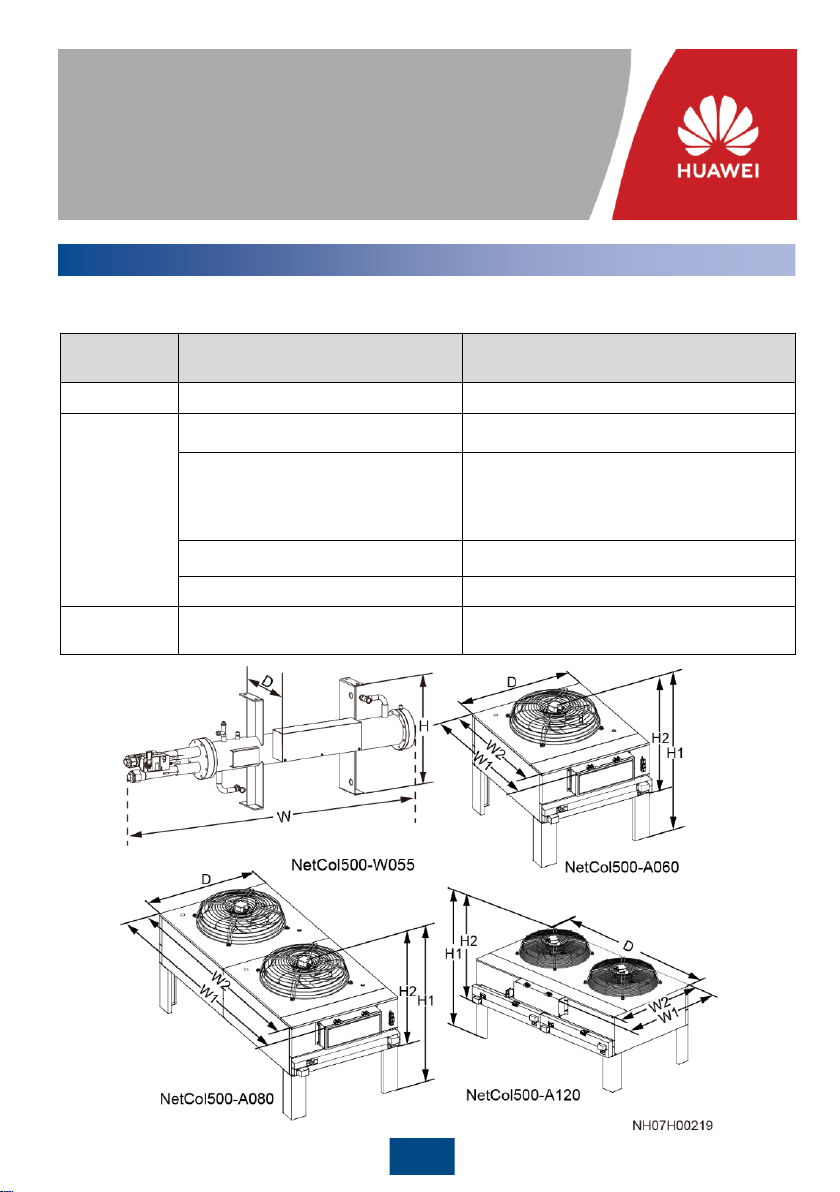
Vertical Installation
5.2
Unit: mm
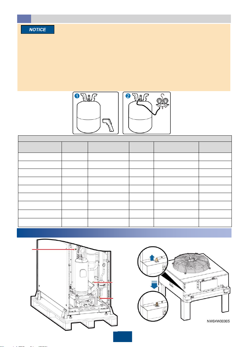
6(Optional) Installing the Water Cooling Module
7Connecting the Refrigerant Pipe
Laying the Engineering Pipe
7.1
1. When outdoor unit is installed horizontally, the outdoor unit and the low-temperature component must be
at the same horizontal plane. When outdoor unit is installed vertically, the installing horizontal plane of
outdoor unit must not be lower than the installing horizontal plane of low-temperature component, and
the height difference cannot exceed 1.5 m.
2. Whencalculatingthe height difference, the compressor base is regarded as the baseline for the indoor
unit, and the condenser top is regardedas the baseline for the outdoor unit.
3. The inverted trap should be higherthan the top copper pipe of the condenser.
Scenario2: Horizontal concrete base installation
Scenario 3: Stack scenario
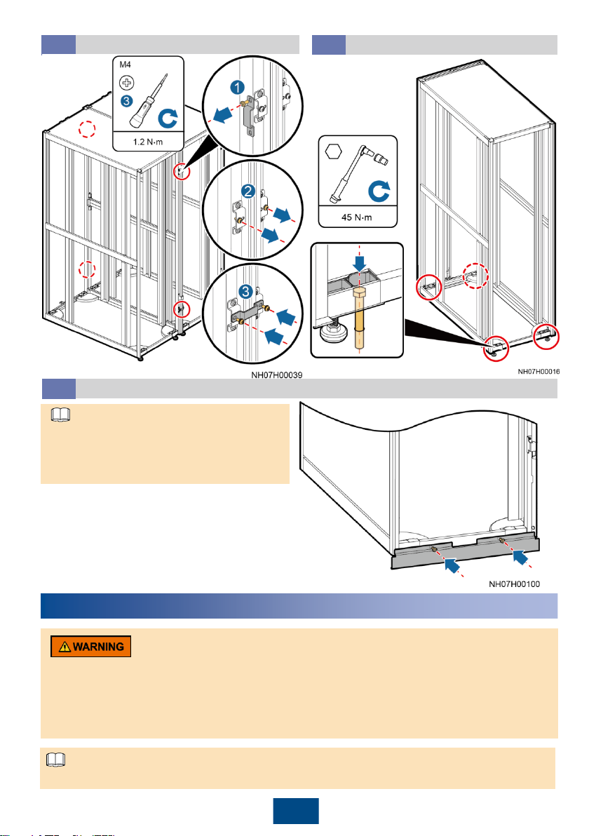
A maximum of four layers of water-cooling modules can be stacked. If four layers of water cooling
modules are stacked, the minimum floor height is 3 m.
Secure the water-cooling module using bolts in the fitting bag on four mounting holes.
Scenario 1: Horizontal
installation top view
Installation environment: enclosed indoor environment in which the temperature and humidity can be
controlled within the ranges of 4℃to 45℃and 5% RH to 90% RH respectively. If the indoor
installation position is ventilated, it should be more than 5 km away from the sea or pollution sources
(such as salt lakes, chemical plants, mineral plants, thermal power plants, and coal mines).
Unit: mm
Pipe
Pipe support
Wall
8
4. When the indoor unit is higher than the outdoor unit, the maximum height difference is 8 m. When the
indoor unit is lower than the outdoor unit, the maximum height differenceis 30 m.
5. Whenwelding pipes, ensure that the pipes are dry. You are recommendedto weld the pipes between
the indoor and outdoor units, then connect the two ends of the pipe to the indoor unit and outdoor unit.
6. Use a rubber hose to connect the nitrogen cylinder which connecting the reducing valve and the end of
the copper pipe, then fill nitrogen at 0.03–0.05 MPa into the copper pipe to avoid internal oxidation.
7. After the pipe in the middle is welded, chargenitrogen into the pipe from one pipe end to clear the
foreign matter inside.
8. Do not expose welding positionsto the environment for a long time. Take sealing measuresfor welding
positions. If foreign matter exists at the welding position, rubber it out using non-water alcohol or damp
cloth before the welding.
Discharging Nitrogen
7.2
Separately exhaust nitrogen from the three needle valves. Separately exhaust nitrogen from the
two needle valves for the water cooling module. When exhausting nitrogen, do not remove the
valve plug in case of losing or damaging it.
Liquid pipe
needle
valve
Low-
pressure
needle
valve
Discharge
pipe needle
valve
9
Take protective measures, such as spreading a piece of wet cloth, around the welding position, to
avoid burning the bottom panel, top panel, side panel, internal components, needle valves, other
pipes, thermal insulation foam, power cables, labels, and tags.
Welding the Indoor Unit Ports
7.3
Top pipe routing
5/8 inch
liquid pipe
7/8 inch
gas pipe
Thermal
insulation foam
5/8 inch
liquid pipe
7/8 inch
gas pipe Thermal
insulation foam
Bottom pipe routing
•When the outdoor is installed
vertically, the gas pipe
should be connected to the
top port and liquid pipe
should be connected to the
bottom port.
•A reducing pipe is required
when welding 3/4 inch
copper pipe to 5/8 inch
connector.
Thermal
insulation foam
5/8 inch liquid pipe
7/8 inch gas pipe
Welding the Outdoor Unit Ports
7.4
10
To indoor unit
liquid pipe To indoor unit gas pipe
To outdoor unit gas pipe
To outdoor
unit liquid pipe
(Optional) Welding the Low
Temperature Component Pipes
7.5 Welding the Water Cooling
Module
7.6
5/8 inch
liquid pipe
7/8 inch
gas pipe
8Connecting Water Pipes
(Optional) Connecting the Humidifier Water Inlet Pipe8.1
1. Clean the water inlet engineering pipes to avoid impurities
entering into the humidifier.
2. When routing pipes from the top, do not route the pipes
over servers or other devices to protect them from being
affected by pipe leaks.
3. Wrap each part of the pipes with thermal insulation foam.
4. Use supports to secure pipes.
Connection method
Top pipe routing
Bottom pipe routing
(1) Reserved connector (7) Reserved connector
(2) Rigid pipe conversion
adapter
(8) Active connector
(3) Rigid pipe (9) Rigid pipe
(4) Pagoda connector (10) Elbow
(5) Hose clamp (11) Rigid pipe
(6) Hose