manuals.online logo
Brands
  1. Home
  2. •
  3. Brands
  4. •
  5. Huawei
  6. •
  7. Freezer
  8. •
  9. Huawei NetCol5000-A011 User manual

Huawei NetCol5000-A011 User manual

HUAWEI TECHNOLOGIES CO., LTD.
NetCol5000-A011 In-row Air Cooled
Smart Cooling Product
Quick Guide
Issue: 06
Date: 2020-10-23
1
Product Model Water
Pump
Heating and
Humidification
Net/Gross
Weight (kg)
Dimensions
(mm)
(H x W x D)
Packaging
Dimensions
(mm)
(H x W x D)
Indoor unit
(including
control unit)
NetCol5000
-
A011
Yes Yes 57/74
486 x 442 x
800
710 x 610 x
1000
Yes No 54/70
486 x 442 x
800
710 x 610 x
1000
Outdoor unit
NetCol500-
A018 N/A N/A 83/99
966 x 1057 x
339
1210 x 1105 x
435
NetCol500-
A020 N/A N/A 101/114
1327 x 966 x
320
1485 x 1082 x
435
1Product Overview
Control Unit
1.1
1. Before installation, see the related manual or instructions to understand the product
information.
2. The model described in this document is fully configured. For the components (electric heater
and humidifier) not configured, skip the corresponding steps.
3. Use insulated tools during installation and operation.
4. Only engineers certified by the manufacturer or its agent are allowed to install, commission,
and maintain the smart cooling product. Otherwise, personal injury or equipment damage
may occur, and the resulting smart cooling product faults are beyond the warranty scope of
Huawei.
5. The site electricians must be qualified.
6. Keep the outdoor unit vertical with a tilt angle not greater than 15°during transportation
and storage.
7. The document is for reference only. If the product described in the document differs from the
actual product, the actual product prevails.
Copyright © Huawei Technologies Co., Ltd. 2020.
All rights reserved.
2
Indoor Unit
1.2
Unit: mm
(1)
Water inlet hole
(2) Strong
-current cable hole
(3) Water outlet hole
(4) Signal cable hole
(5) Gas pipe stop valve
(6) Liquid pipe stop valve
(Front view) (Rear view) (Side view)
(Front view)
(Top view)
Outdoor Unit
1.3
(Front view)
(Top view)
NetCol500-A018 NetCol500-A020
Unit: mm
2Materials
Delivered
Materials
Hose clamps, cable ties, humidifier water inlet pipe (optional
with humidifier
), guide
rails, drainpipe connector, OT terminals, cord end terminals
Engineering
Procurement
Refrigerant
pipe
Liquid pipe: Copper pipe with an outer diameter of 3/8 inch (9.52 mm),
pipe wall thickness of 0.75 mm, and operating pressure of greater than
or equal to 4.5 MPa
Gas pipe: Copper pipe with an outer diameter of 5/8 inch (15.88 mm),
pipe wall thickness of 1.0 mm, and operating pressure of greater than
or equal to 4.5 MPa
Thermal insulation foam: thickness ≥ 13 mm
Refrigerant pipe support (see page 4)
Oil trap (see page 4)
3
Engineering
Procurement
Water pipe
Humidifier water inlet pipe (optional
with humidifier):

Rigid pipe conversion adapter: G 1/2-
inch outer screw thread to rigid
pipe connector, rigid pipe (made of PP-R or other materials)

Hose conversion adapter: G 1/2-inch outer screw thread to pagoda
connector, hose (made of EPDM or other materials)
Drainpipe:

Rigid pipe conversion adapter: BSPP 1/2-inch inner screw thread to
rigid pipe connector, rigid pipe (made of PP-R or other materials)

Hose conversion adapter: BSPP 1/2-inch inner screw thread to
pagoda connector, hose (made of EPDM or other materials)
Thermal insulation foam: thickness ≥ 6 mm
Cable and
others
Outdoor unit power cable (3 x 6 mm
2
), signal cable for the indoor and
outdoor units
(3 cores outdoor shielded cable, 16-22 AWG), M10
expansion bolts (4 PCS)
Special Tools
and Materials
Requirements

Vacuum pump: Flow: 2–4 L/s, absolute vacuum: ≤ 60 Pa.

Pressure gauge and leather hose: Dedicated to R410A, pressure gauge
measurement range ≥ 4.0 MPa, and the leather hose tolerance range ≥ 4.5 MPa
.

Welding torch and welding rod: Silver-copper welding rod that contains 5% of
silver.

Nitrogen reducing valve: A reducing valve must be installed on the head of the
nitrogen cylinder, and the reducing valve range ≥ 4.0 MPa.

Dry nitrogen.
R410A Refrigerant
2.1
Do not use unqualified refrigerant. Huawei will not be liable for any equipment damage caused
by unqualified refrigerant.
Refrigerant from name brands such as DuPont, Daikin, and Honeywell are recommended. You
can verify the refrigerant authenticity in the following ways:
1. Dial the refrigerant manufacturer's hotline to confirm the refrigerant manufacturer
authenticity.
2. Place the refrigerant tank indoors for 24 hours. Use a point thermometer to measure the
outer surface temperature of the refrigerant tank (figure 1), and connect a pressure gauge
to the tank to measure the internal pressure (figure 2). Find the saturation pressure
corresponding to the measured outer surface temperature from the table on the next page.
If the deviation between the saturation pressure and the measured internal pressure is
greater than 0.2 MPa, the refrigerant does not meet the requirements, and needs to be
replaced.
1 MPa = 10 bar
1 MPa ≈ 145 psi
1 MPa ≈ 10.2 kgf/cm2
4
R410A Saturation Pressure (Surface Pressure) Table
Temperature
(
°C)
Saturation
Pressure (MPa)
Temperature
(
°C)
Saturation
Pressure (MPa)
Temperature
(
°C)
Saturation
Pressure (MPa)
10 0.99 19 1.31 28 1.69
11 1.02 20 1.35 29 1.74
12 1.05 21 1.39 30 1.79
13 1.09 22 1.43 31 1.84
14 1.12 23 1.47 32 1.89
15 1.16 24 1.51 33 1.94
16 1.19 25 1.56 34 1.99
17 1.23 26 1.60 35 2.05
18 1.27 27 1.65 36 2.10
Oil Trap
2.2
Unit: mm
Pipe
support
Pipe Support
2.3
1. Height of the U-shaped clamp H = Pipe diameter (with thermal insulation foam) –5 mm.
2. The material for pipe supports and clamps should meet outdoor application requirements.
3. When the pipe is straight, add a support every 1500 mm. When the direction of the pipe is
changed, add a support at the position that is 500 mm away from the changing point.
5
3(Optional) Installing an Indoor Unit in the First IT
Cabinet to the Left of the Converged Cabinet
Moving the Mounting Bar
3.1
Remove the beams in the IT cabinet and move the entire mounting bar of front door 50 mm
towards the exterior.
Unit: mm
This section applies to the scenario with three smart cooling products. If there are only two smart
cooling products, skip this section.
Installing Guide Rails at the Bottom of the IT Cabinet
3.2
6
3.2 Floating Nut Installation Positions
3.3
Installing Floating Nuts
3.4
Installing the Guide Rails
3.5
7
(Optional) Installing the Air Director
3.8
If there are more than six cabinets in a single-row cold aisle, install an air director in front of the
indoor unit.
Securing the Control Unit
3.7
Securing the Indoor Unit
3.6
4Installing an Outdoor Unit
Installing the NetCol500-A018 is used as an example in the guide, and it is the same as
installing the NetCol500-A020.
8
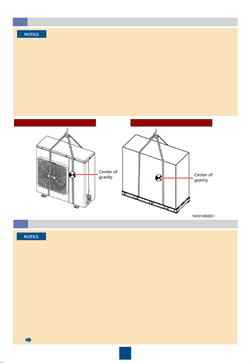
Hoisting the Outdoor Unit
4.1
•Select a hoisting mode based on site requirements. Hoist the packed outdoor unit using two
ropes that are at least 8 meters and raise it gently while keeping its balance. If the outdoor
unit has no package or the package is damaged, protect the outdoor unit using pads or
packing materials during the hoisting.
•When an outdoor unit is to be installed on an external wall, route the ropes through the
inner side of the two bottom feet. When an outdoor unit is to be installed on a rooftop, route
the rope through the inner side of the two wooden supports. This measure avoids the rope
from slipping during hoisting.
•When an outdoor unit is to be installed on a rooftop, you do not have to remove the
package during the hoisting. Otherwise, the outdoor unit appearance may be slashed.
•Keep the outdoor unit vertical and exercise caution when transporting and hoisting it.
•Do not hold the fan guard on the shell. Otherwise, it will be deformed.
•Do not touch the fan blades using hand or any other object.
•Secure the outdoor unit to prevent it from falling down in an earthquake or a strong wind.
Installed on an external wall Installed on a rooftop
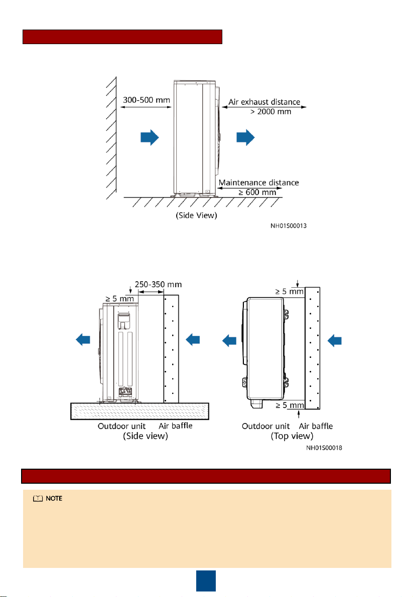
Space Requirements for Installing and Maintaining the Outdoor Unit
4.2
•To avoid fire disaster, install an outdoor unit in a dry and well-ventilated place without
flammable gas leakage.
•Select a place away from direct sunshine and radiation from other heat sources. If the sunshine
or heat radiation cannot be avoided, cover the outdoor unit.
•Do not install an outdoor unit in a place with much salt or corrosive gas.
•When installing the outdoor unit, ensure that the air intake vent and air exhaust vent of the
condenser are not dirty or blocked. Install an outdoor unit in clean areas that are away from
residential areas.
•At a high place with strong winds, install the outdoor unit against a wall to ensure the normal
operating of fans. Install baffle plates when necessary, take this measure to prevent wind from
blowing down the outdoor unit.
•Try to install an outdoor unit against a wall. If the site conditions cannot meet the requirements
and the local outdoor temperature may be below –10°C (NetCol500-A018) or 0°C(NetCol500-
A020), prepare and install an air baffle by referring to the figures on the following slide. The air
baffle height and width should be greater than or equal to the outdoor unit height and width,
respectively.
•If the site installation environment is complicated and the preceding conditions are not met,
contact Huawei technical support.
•indicates the wind direction.
9
A single outdoor is recommended to be installed against a wall.
Space Requirements for Single Outdoor Unit
If the air baffle is needed, place an air baffle at the air intake side of the outdoor unit based on
the following figure.
Space requirements for maintaining the single wall-mounted outdoor unit
•The bearing capacity of the support platform is more than 230 kg.
•Reserve no less than 300 mm from the left or right side of the outdoor unit for
maintenance personnel to walk.
•Grid structure is recommended to avoid the air exhaust and intake of the smart cooling
product being affected by the guardrail structure.
•The picture is only for reference, adjust based on the on-site situation if necessary.
10
Concrete Base Requirements
Space Requirements for Multiple Outdoor Units
If the air baffle is needed, place an air baffle at the air intake side of each outdoor unit.
11
Removing the Pallet
4.3 Securing the Outdoor Unit
4.4
For details about the
outdoor dimensions,
see 1.3 Outdoor Unit.
Laying Out Pipes
5.1
(1) Oil trap (2) Tilted gas pipe (3) Tilted liquid pipe
1. The height deviation refers to the distance from the stop valves of the indoor unit to the stop
valves of the outdoor unit.
2. is a sign of a tilt, and it indicates that the scale of the pipe tilt is at least 1:200. The pipe
tilt direction should be consistent with the hypotenuse of the right triangle.
3. The refrigerant pipe should be wrapped with thermal insulation foam.
4. Keep the pipe dry during welding.
5. After the pipe between the indoor and outdoor units are welded, blow nitrogen from one end
into the pipe to clear foreign matter.
6. The welded joints cannot be exposed for a long period of time and must be sealed. If there is
foreign matter at the welding joints, clean the joints using anhydrous alcohol or a wet cloth,
and wait for the joints to dry up before welding.
7. No face-down bonding.
5Installing the Refrigerant Pipe
12
5Installing the Refrigerant Pipe
1. Keep at least 25 mm between pipes.
2. When connecting the indoor and outdoor units, you are advised to connect pipes to the
outdoor unit first. Seal the pipe if the welding break will exceed 15 minutes to prevent dust
and water from entering the pipe.
3. Take appropriate sealing and protection measures when routing welded pipes through holes
to prevent air channel leaks and copper pipe damage. Otherwise, other components may be
damaged by foreign matter.
4. Avoid elbows and ensure that the connection between the indoor and outdoor units is the
shortest.
Wall
Pipe
Pipe support
Laying Out Pipes Inside the Cabinet
5.2
1. When routing pipes upward inside an IT
cabinet, remove the cable ring from the pipe
side in the rear of the cabinet.
2. Install the binding plate using the
screws removed in the previous step.
Upward pipe routing
3. Route pipes inside the cabinet.
13
Downward pipe routing
14
1. Connect the liquid pipe stop valve first, and then the gas pipe stop valve.
2. Tighten the liquid pipe stop valve using a 27# torque wrench to a torque of 35–37 N·m.
Tighten the gas pipe stop valve using a 36# torque wrench to a torque of 50–52 N·m
3. When tightening a stop valve using a torque wrench, secure the hex nut of the active
connector at the welded copper pipe to prevent the copper pipe from turning and further
deforming as the stop valve is being tightened.
4. Ensure that you tighten the valve to the specified torque. The failure torque for the nut of the
liquid pipe stop valve is 70 N·m and that for the nut of the gas pipe stop valve is 100 N·m.
The torque greater than the failure torque will damage the screw thread.
Connecting the Indoor Unit
5.3
Connecting the Outdoor Unit
5.4
The outdoor unit has been charged R410A refrigerant before delivery. To avoid refrigerant leaks,
do not open the outdoor unit stop valve before vacuumizing is complete.
Installing Nuts
5.5
When installing a needle valve nut and rear cover nut, use the torque specified in the following
table.
15
Item
Needle Valve Nut Rear Cover Nut
Nut Size
Tightening Torque (N·m)
Nut Size
Tightening Torque
(N·m)
Liquid pipe stop valve
17# 10 19# 15–17
Gas pipe stop valve 17# 10 30# 20–22
Needle
valve nut
Rear
cover nut
Black plastic nut
(1) Connector with inner screw thread: G 1/2-inch, fittings
delivered with the water inlet pipe
(2) Rigid pipe conversion adapter: G 1/2-inch outer screw
thread to rigid pipe connector, engineering procurement
(3) Rigid pipe: made of PP-R or other material, engineering
procurement
(4) Pagoda conversion adapter: G 1/2-inch outer screw
thread to pagoda connector, engineering procurement
(5) Hose clamp, delivered with the water inlet pipe
(6) Hose: made of EPDM or other material, engineering
procurement
6Installing Water Pipes
Installing Water Inlet Pipes
6.1
16
Upward water inlet pipe routing
IT Cabinet Converged Cabinet Converged CabinetIT Cabinet
Downward water inlet pipe routing
After routing water pipes, secure them to the refrigerant pipe using cable ties. If the pipes are
routed downwards, not only secure the pipes but also seal the cable hole using firestop putty.
Installing a Drainpipe
6.2
(1) Drainpipe connector: BSPT 1/2-inch, delivered with the smart
cooling product
(2) Rigid pipe conversion adapter: BSPP 1/2-inch inner screw thread
to rigid pipe connector, engineering procurement
(3) Rigid pipe: made of PP-R or other material, engineering
procurement
(4) Pagoda conversion adapter: BSPP 1/2-inch inner screw thread to
pagoda connector, engineering procurement
(5) Hose clamp, delivered with the smart cooling product
(6) Hose: made of EPDM or other material, engineering procurement
•In upward pipe routing, install the check valve, engineering hose, and drainpipe connector by
performing steps 1–3. In downward pipe routing, install the drainpipe connector by performing step 3.
•The drainpipe inside the indoor unit should be wrapped with the thermal insulation pipe in accessories.
•The drainpipes must have gradients (>1:50), and stagnant water is not allowed.
17
Upward drainpipe routing Downward drainpipe routing
After routing water pipes, secure them to the refrigerant pipe using cable ties. If the pipes are routed
downwards, not only secure the pipes but also seal the cable hole using firestop putty.
IT Cabinet Converged Cabinet IT Cabinet Converged Cabinet
7Installing Cables
M5 (3 PCS)
2 N•m
M3 (3 PCS)
0.6-0.8 N•m
18
No.
Cable Name
From
To
1
Electric heater contactor
cable (required if an electric
heater is configured
)
Converged cabinet XT4
-6 and XT4
-
5 correspond to smart cooling
products 1 and 2, respectively. The
third smart cooling product is not
configured with this cable by
default.
Contactor KM1 of the
corresponding smart cooling
product
The third smart cooling
product is not configured
with this cable by default.
2
Control unit input power
cable
Converged cabinet XT4
-4
INPUT1 port on the control
unit
3
Outdoor unit power cable (3
x 6 mm
2)
L (converged cabinet
XT4-1, XT4-
2,
and XT4
-3 correspond to outdoor
units 3, 2, and 1, respectively.),
N
bar, PE bar
L, N, and ground ports on
the electric control box of
the outdoor unit
4
Signal cable for the indoor
and outdoor units (3
cores
outdoor shielded cable, 16
-
22
AWG)
X2.1, X2.2, and X2.3 ports on the
indoor unit
P, Q, and E ports on the
electric control box of the
outdoor unit
5
J1 cable
X101, X102, and X103 ports on the
indoor unit
J1 port on the control unit
6
J2 cable
X101, X102, and X103 ports on the
indoor unit
J2 port on the control unit
7
Control unit output power
cable
X1.1, X1.2, X1.3, and FU1
-
FU3 ports
on the indoor unit
OUT1 port on the control
unit
8
J3 cable
X101, X102, and X103 ports on the
indoor unit
J3 port on the control unit
9
J4 cable
X101, X102, and X103 ports on the
indoor unit
J4 port on the control unit
10
Temperature/Humidity (T/H)
sensor cable
RS485/12V port on the control unit
T/H sensor
11
ECC800 cable
FE
-2 port on the control unit
•If the smart ETH gateway
is configured, connect the
cable to the PoE
port on
the smart ETH gateway.
•If no smart ETH gateway
is configured, connect the
cable to the WAN_2 port
on the ECC800.
12
Ground cable
Ground point on the control unit
IT cabinet ground copper
bar
8Verifying the Installation
•Do not pull cables J1, J2, J3, and J4 and their terminals casually. Ensure that the cables
are connected securely.
•If there are only two smart cooling products in the converged cabinet, you only have to
connect cables 3, 4, and 10, since other cables are factory-installed. If there are three
smart cooling products, all cables except 1 to the third smart cooling product have to
be connected onsite.
•The length of signal cable for the indoor and outdoor units cannot exceed 200 meters.
•The signal cable should be shielded, and the shield layer shall be grounded.
19
1. The stop valves for the gas pipe and liquid pipe on the indoor unit side are open, and those
on the outdoor unit side are closed.
2. (Leakage test with nitrogen) Inject nitrogen until the pressure reaches 3.0 MPa. Verify that
the pressure does not decrease after 24 hours under a stable ambient temperature. If any
leak is found after pressure preservation, check the pipe for leaks, especially the welding
points and stop valves.
3. (Vacuumizing) Replace the reducing valve and nitrogen cylinder with a vacuum pump.
Perform vacuumizing for at least 80 minutes and ensure that the final absolute pressure is
not greater than 60 Pa. When the final pressure does not decrease any more, continue to
vacuumize for 10 minutes. After vacuumizing is complete, close the vacuum pump and all
valves, and preserve the pressure for 10 minutes. Ensure that the absolute pressure does not
exceed 90 Pa. If the minimum reading of the pressure gauge is greater than 60 Pa, ensure
that the pointer stays at the smallest scale of the pressure gauge and preserve the pressure
for 1 hour. Then check that the pressure does not rise.
4. Open the stop valves for the gas pipe and liquid pipe of the outdoor unit.
9Leakage Test with Nitrogen and Vacuumizing
•After the outdoor unit stop valve is opened, the refrigerant in the outdoor unit flows to
the engineering pipe and indoor unit pipe. When performing other operations, be careful
to prevent refrigerant from spraying out.
•After the vacuumization and before removing the rubber hose, ensure that there is
positive pressure inside the refrigerant pipe of the indoor unit. For detailed operations,
see step 1–4 in section "Commissioning Procedure".
Item Check That
Check Result
Indoor fan
The fan is secured. The fan has no foreign matter inside.
□
Passed
□
Failed
Wet film
humidifier
(optional)
The water inlet solenoid valve, humidifier water pump, and wet film
are secured.
□
Passed
□
Failed
Humidifier
float
The humidifier float is secured. The fasteners for the humidifier float
are secured.
□
Passed
□
Failed
Liquid level
detector
The liquid level detector is secured. The fasteners for the liquid level
detector are secured.
The low liquid level detector functions flexibly.
□
Passed
□
Failed
Return air
filter
The arrow direction of the return air filter is consistent with the return
air direction.
□
Passed
□
Failed
Outdoor
unit
The outdoor unit is secured. The outdoor unit air intake and exhaust
vents are not blocked. The outdoor unit installation meets
requirements.
□
Passed
□
Failed
Pipe
Pipe connectors are correct. The refrigerant pipe tilts and has supports.
The hose clamps and cable ties of the drainpipe are secured. The
refrigerant pipe and water pipe are wrapped with thermal insulation
foam. All pipes have been checked for leaks. Water pipe joints have
been sealed by sealant. The
water inlet pipe and drainpipe also have
been checked for leaks. All pipes are not bent by a large angle.
□
Passed
□
Failed
Cable
The input voltage is within the range of rated voltage
±
10%, and the
input frequency is within the range of rated frequency
±3 Hz. Cables
are not damaged. All cables, connectors, and bolts are secured. All
devices are correctly grounded.
□
Passed
□
Failed

Other Huawei Freezer manuals

Huawei NetCol8000-E220 User manual

Huawei

Huawei NetCol8000-E220 User manual

Huawei FusionCol8000-E140 User manual

Huawei

Huawei FusionCol8000-E140 User manual

Huawei NetCol5000-A050 User manual

Huawei

Huawei NetCol5000-A050 User manual

Huawei NetCol8000-C190 User manual

Huawei

Huawei NetCol8000-C190 User manual

Popular Freezer manuals by other brands

Pkm GS 175.4 A+ NF instruction manual

Pkm

Pkm GS 175.4 A+ NF instruction manual

Zanussi ZQF11430DA user manual

Zanussi

Zanussi ZQF11430DA user manual

Farrar Scientific ULC Series instruction manual

Farrar Scientific

Farrar Scientific ULC Series instruction manual

Electrolux ECF24460W user manual

Electrolux

Electrolux ECF24460W user manual

Hisense RB440N4WWF User's operation manual

Hisense

Hisense RB440N4WWF User's operation manual

KitchenAid KRSC 9007 Assembly instructions

KitchenAid

KitchenAid KRSC 9007 Assembly instructions

Frigidaire FFU2124DW Factory parts catalog

Frigidaire

Frigidaire FFU2124DW Factory parts catalog

SEVERIN KS 9807 Instructions for use

SEVERIN

SEVERIN KS 9807 Instructions for use

Petromax kx25 user manual

Petromax

Petromax kx25 user manual

Vestfrost VF 11186 X NoFrost user manual

Vestfrost

Vestfrost VF 11186 X NoFrost user manual

True TR3F-3S Specifications

True

True TR3F-3S Specifications

Frigidaire FCCS071QWA instructions

Frigidaire

Frigidaire FCCS071QWA instructions

Currys Essentials CTT50W15 instruction manual

Currys Essentials

Currys Essentials CTT50W15 instruction manual

Frigidaire FFFH17F2QW use & care

Frigidaire

Frigidaire FFFH17F2QW use & care

ZANKER ZKC380AP OPERATING AND INSTALLATION Manual

ZANKER

ZANKER ZKC380AP OPERATING AND INSTALLATION Manual

SPX Cooling Technologies MH Fluid Cooler user manual

SPX Cooling Technologies

SPX Cooling Technologies MH Fluid Cooler user manual

Dometic CDF 26 operating manual

Dometic

Dometic CDF 26 operating manual

Vestfrost VR-BF27952H1S Operation manual

Vestfrost

Vestfrost VR-BF27952H1S Operation manual

manuals.online logo
manuals.online logoBrands
  • About & Mission
  • Contact us
  • Privacy Policy
  • Terms and Conditions

Copyright 2025 Manuals.Online. All Rights Reserved.