manuals.online logo
Brands
  1. Home
  2. •
  3. Brands
  4. •
  5. Huayu
  6. •
  7. Industrial Electrical
  8. •
  9. Huayu HY-1000-Plus User manual

Huayu HY-1000-Plus User manual

Huayu(Ningbo)New Energy Technologies Co.,Ltd. All rights reserved.
c
QUICK INSTALLATION GUIDE
Installing a Huayu HY-1000/800-Plus Microinverter
A PV system by Microinverters is simple to install. Each Microinverter easily mounts on the PV racking system, directly beneath the PV module. Low voltage DC
wires connect from the PV module directly to the Microinverter, eliminating the risk of high DC voltage. Installation MUST comply with local regulations and
technical rules.
Special Statement! An AC GFCI device should not be used to protect the dedicated circuit to the Microinverter even though it is an outside circuit. None of the
small GFCI devices(5~30mA) are designed for back feeding and will be damaged if so. In a similar manner, AC AFCIs have not been evaluated for back
feeding and may be damaged if back feed with the output of a PV inverter.
WARNING
Perform all electrical installations in accordance with local electrical codes.
Be aware that only qualified professionals should install and/or replace Microinverters.
Before installing or using a Microinverter, please read all instructions and warnings in the technical documents and on the Microinverter itself
as well as on the PV array.
Be aware that installation of this equipment includes the risk of electric shock.
Do not touch any live parts in the system, including the PV array, when the system has been connected to the electrical grid.
Strongly recommend to install surge protection devices in the dedicated combiner box.
Additional Installation Components
AC Male and Female Interconnection Connectors(offered separately)
Sealing end caps(offered separately)
Required Parts and Tools
In addition to your PV array and its associated hardware, the following
items are needed for installation:
An AC connection junction box
Mounting hardware suitable for module racking system
Sockets and wrenches for mounting hardware
Continuous grounding conductor and grounding washers
A Phillips screwdriver
A torque wrench
Simple to Install
You can install individual PV modules in any combination of Module
quantity and orientation, different type and power rate. The Ground
wire (PE) of the AC cable is connected to the chassis inside of the
Microinverter, potentially eliminating the installation of grounding
wire(check local regulation).
Huayu monitoring data logger connects the microinverter to the
Huayu Portal server via the cloud, allowing for collection of production
and other data useful in system monitoring and trouble shooting.
Users can monitor and manage the microinverter through
corresponding website or APP.
1
2
1
2
3
4
5
6
If the PLC signal is weak, it may be significantly improved by moving the data logger to closer to the microinverter arrays, and/or farther away from other interferers,
and/or install a signal filter (LCF) to reduce the interference to PLC communication.
NOTE:
INSTALLATION
Specifications subject to change without notice - please ensure you are using
the latest manual found at the manufacturer website: www.huayu-energy.com
When AC power is applied but Microinverter is not started up, about 0.1A
current and 25VA(W) power for each Microinverter may be measured by a
power meter, this power is reactive power, not from grid.
NOTE:
NOTE:
Step 5- Install an AC Cable Protective End Cap at the End
of AC Cable
7.5
NOTE:
The microinverter is powered on when sufficient DC voltage from the module
is applied. The status LED will start flashing after sufficient DC power is applied
as an indication that the microinverter is live.
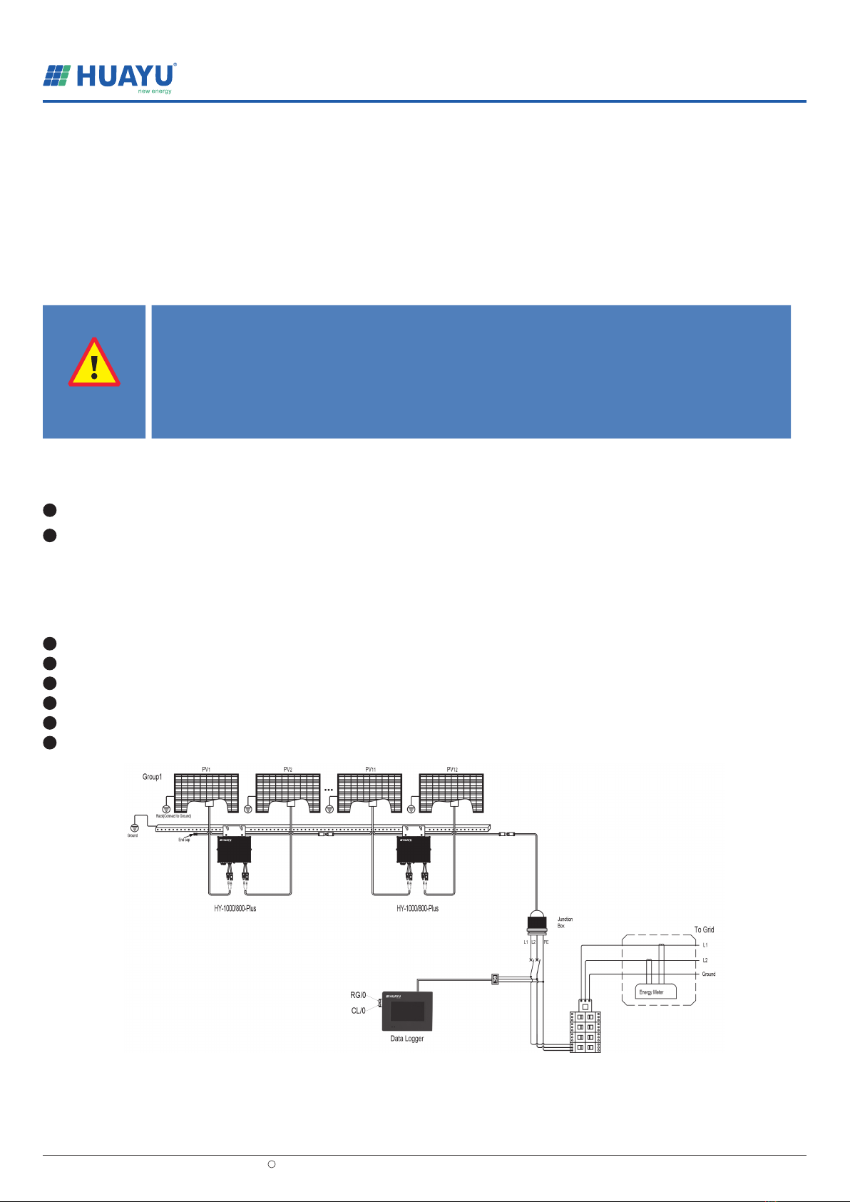
Completely install all HY-1000/800-Plus and all system inter-wiring connections
prior to installing the PV modules.
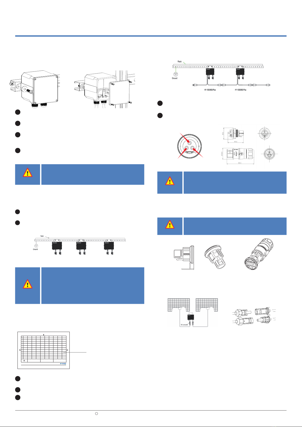
Step 6- Connect Microinverter to PV Modules
WARNING
DO NOT exceed maximum number of Microinverters in an AC branch
circuit.For 12awg trunk cable, each HY-1000/800-Plus ac branch circuit
must be sourced from a dedicated branch circuit protected by a 20a
maximum breaker.
WARNING
Installed on all unused ac connectors. Unused ac HY-1000/800-Plus
wire harness connectors are live when the system is energized by the
utility system.
L(L1) N(L2)
PE
Installation Procedure
Step 1- Install AC Branch Circuit Junction Box
Install an appropriate junction box at a suitable location on the PV racking
system(typically at the end of a branch of modules).
Connect the open wire end of the AC cable into the junction box using an
appropriate gland or strain relief fitting.
Wire the conductors of the AC(127/220/230): L - red; N - black;
PE - yellow green. Wire the conductors of the AC(208/240): L1- red;
L2 - black; PE - yellow green.
Connect the AC branch circuit junction box to the point of utility
Interconnection.
1
2
3
4
Huayu(Ningbo)New Energy Technologies Co.,Ltd. All rights reserved.
c
Step 2- Attach Microinverters to Racking System or
the PV Module Frame
Prior to installing any of Microinverters, verify that the utility voltage at
the point of common connection matches the voltage rating on
Microinverter label.
Do not place the Microinverter(including DC and AC connectors)
where exposed to the sun, rain or snow, even gap between modules.
Allow a minimum of 3/4 inch(2cm). between roof and bottom of the
Microinverter to allow proper air flow.
WARNING
Wiring colour code can be different according to local regulation,check
all the wires of the installation before connecting them to the AC cable.
Wrong cabling can damage irreparably Microinverters,such an issue is
not covered by the warranty.
Mark the location of the Microinverter on the rack, with respect
to the PV module junction box or any other obstructions.
Mount one Microinverter at each of these locations by
recommended hardware.
1
2
1
2
3
Step 3- Create an Installation Map
Peel the removable serial number label from each microinverter and affix
it to the respective location on the paper installation map.
Fill in the monitoring system account information to the installation map
Create a paper installation map to record microinverter serial numbers and position
in the array.
Always keep a copy of the installation map for your records.
Affix serial number labels
WARNING
A
12345678910
Customer:
1. Affix the serial number label to the respective location of the map.
2. Scan related QR Code of Microinverter and upload it to Huayu Monitoring platform.
Panel Group:
Azimuth:
Tilt:
Sheet____of____
Monitoring System Account:
Installer:
B
C
D
E
F
G
H
J
K
L
W E
N
S
N
Step 4- Connect the Microinverters in Parallel
2Plug the male AC connector of Microinverter into the female connector to
get it connected. AC connector interface is as follows.
1Check Microinverter technical data for the maximum allowable number of
Microinverters on each AC branch circuit.
HY-1000/800-Plus
A
12345678910
Customer:
1. Affix the serial number label to the respective location of the map.
2. Input the serial number through data logger touch screen or Huayu Monitoring platform.
Panel Group:
Azimuth:
Tilt:
Sheet____of____
Monitoring System Account:
Installer:
B
C
D
E
F
G
H
J
K
L
W E
N
S
N

Other manuals for HY-1000-Plus

1

This manual suits for next models

1

Popular Industrial Electrical manuals by other brands

Murata GRM0335C1E561GA01 Series Reference sheet

Murata

Murata GRM0335C1E561GA01 Series Reference sheet

Grundfos SMART Digital S-DDE Installation and operating instructions

Grundfos

Grundfos SMART Digital S-DDE Installation and operating instructions

National Instruments SCXI-1332 installation instructions

National Instruments

National Instruments SCXI-1332 installation instructions

LEGRAND 0 901 03 manual

LEGRAND

LEGRAND 0 901 03 manual

Murata GRM188R61E475KE11 Series Reference sheet

Murata

Murata GRM188R61E475KE11 Series Reference sheet

Siemens SIRIUS 3RA132.-8XB30 operating instructions

Siemens

Siemens SIRIUS 3RA132.-8XB30 operating instructions

Cypress CVX-OPTW product manual

Cypress

Cypress CVX-OPTW product manual

Murata GRM0225C1E6R0CDAE Series Reference sheet

Murata

Murata GRM0225C1E6R0CDAE Series Reference sheet

Murata GRM0335C1E6R0BA01 Series Reference sheet

Murata

Murata GRM0335C1E6R0BA01 Series Reference sheet

Murata GRM0335C1E1R0BA01 Series Reference sheet

Murata

Murata GRM0335C1E1R0BA01 Series Reference sheet

Murata GRT188R61C475KE13 Series Reference sheet

Murata

Murata GRT188R61C475KE13 Series Reference sheet

Datcon DT1362 operating instructions

Datcon

Datcon DT1362 operating instructions

METER ZL6 manual

METER

METER ZL6 manual

Klockner Moeller FIP30-NZM 74 installation instructions

Klockner Moeller

Klockner Moeller FIP30-NZM 74 installation instructions

LED Group Robus R60BHPC-01 quick start guide

LED Group

LED Group Robus R60BHPC-01 quick start guide

Weidmüller PVNCM1I3S1F3V101TXPX10 operating instructions

Weidmüller

Weidmüller PVNCM1I3S1F3V101TXPX10 operating instructions

Murata GQM2195C2E4R7BB12 Series Reference sheet

Murata

Murata GQM2195C2E4R7BB12 Series Reference sheet

Siemens TA6PG750 installation instructions

Siemens

Siemens TA6PG750 installation instructions

manuals.online logo
manuals.online logoBrands
  • About & Mission
  • Contact us
  • Privacy Policy
  • Terms and Conditions

Copyright 2025 Manuals.Online. All Rights Reserved.