HUAYUAN SK Series User manual

SK Series Oil-Free Scroll Air
Compressor
User Manual

Preface
Thank you for purchasing SK series oil-free scroll air compressors developed and produced by
Huayuan Precision Machine (Shenzhen) Co., Ltd.
SK series oil-free scroll air compressors are characterized by advanced performance indicators,
excellent manufacturing technology and low operating noise, and they can be arranged and used
nearby on site. No lubricating medium is required during compression. Discharged compressed
air is clean without oil and would not cause any pollution to end air equipment with a good
protection to the health of field personnel. Due to completely oil-free operation, the air
compressors do not need oil-air separation device, without hidden trouble of oil leakage and less
maintenance during lifelong use.
This user manual describes the basic information and application of SK series products. Please
carefully read this manual before use, and carry out operations in strict accordance with the
instructions in it. In case of any ambiguities, call our customer service center or local authorized
dealers for technical support.
Special Statement
●We are committed to continuous improvement and design optimization of our products. The
product information provided herein is subject to change without notice.
●The illustrations in this user manual are only for general description of products, and may not be
exactly the same as the products you ordered.
●Failures in compressors may cause major safety accidents or personal injuries. Be sure to install
necessary safety protection devices.

Contents
1. Safety Precautions 1........................................................................................................................................
1.1 Important Notice 1.................................................................................................................................
1.2 Signs and their Meanings 1...................................................................................................................
2. Product Information 2......................................................................................................................................
2.1 Model Implication 2..............................................................................................................................
2.2 Description of Nameplate 2...................................................................................................................
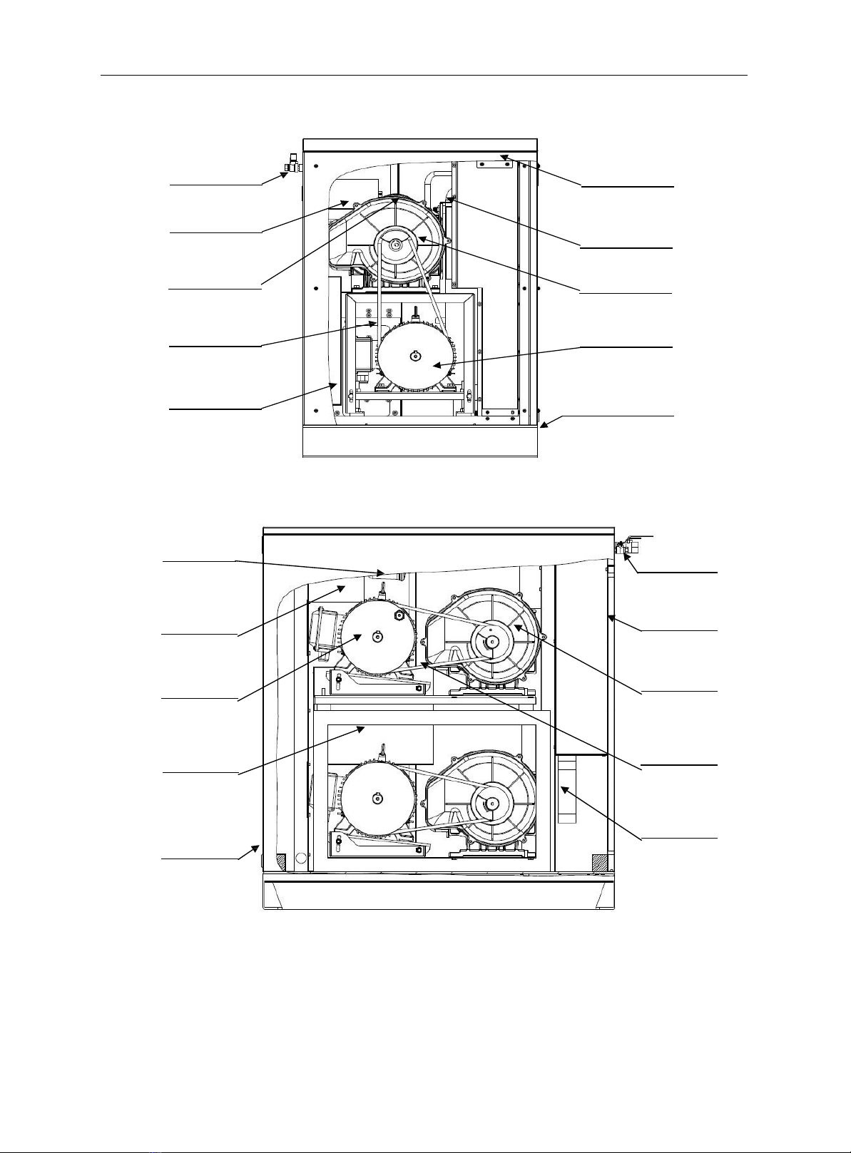
2.3 Description of Components 3................................................................................................................
2.4 Technical Specifications 4.....................................................................................................................
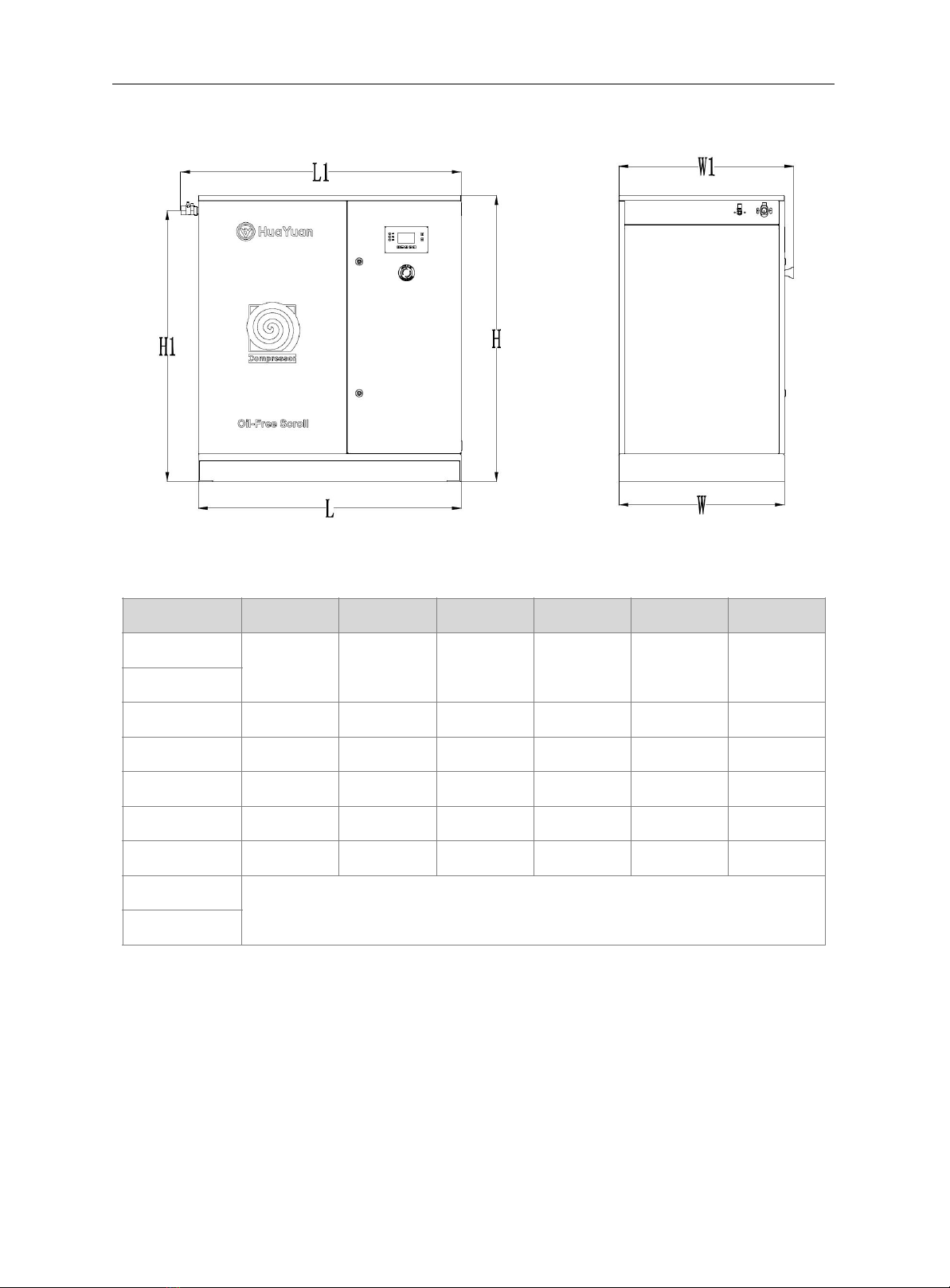
2.5 Dimensions 5.........................................................................................................................................
3. Installation 6....................................................................................................................................................
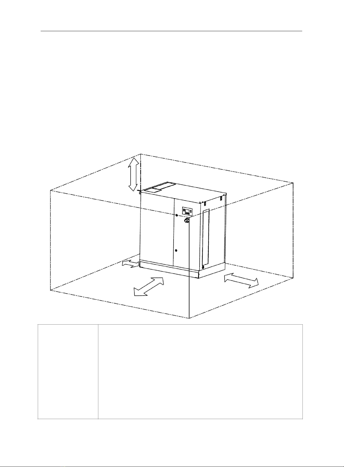
3.1 Operating Environment 6......................................................................................................................
3.2 Check before Installation 6....................................................................................................................
3.3 Installation Requirements 7...................................................................................................................
3.4 Piping and Air Storage 8........................................................................................................................
3.5 Main Circuit and Terminal Definition 9................................................................................................
3.6 Wiring and Connection 10.....................................................................................................................
4. Debugging and Use 11....................................................................................................................................
4.1 Description of Operation Panel 11........................................................................................................
4.2 Power-on and Trial Operation 12..........................................................................................................
4.3 Instructions on Use 13...........................................................................................................................
4.4 Precautions for Use 13..........................................................................................................................
5. Maintenance and Check 14.............................................................................................................................
5.1 Check Items 14......................................................................................................................................
5.2 Routine Maintenance 15........................................................................................................................
6. Troubleshooting 17..........................................................................................................................................
7. After-sales Service and Warranty 18...............................................................................................................
7.1 Installation and Training 18..................................................................................................................
7.2 Warranty Service 18..............................................................................................................................

1
1. Safety Precautions
1.1 Important Notice
●This user manual clearly describes the correct use of SK series oil-free scroll air
compressors. Please read the manual carefully before installing, operating and maintaining
the products. Strictly comply with all safety precautions to ensure personal and equipment
safety.
●The precautions marked with "Caution" and "Warning" in this manual do not represent all
safety precautions that should be observed, but only serve as a supplement to all safety
precautions herein.
●The company does not assume any legal responsibility for personal safety accidents and
property losses caused by violations or incorrect operations.
1.2 Signs and their Meanings
It indicates that failure to operate correctly as required may result in death or serious
bodily injury.
It indicates that failure to operate correctly as required may result in minor bodily
injury or equipment damage.
Warning
Caution
Storage and Transportation
Caution
①
Air compressors must be properly packaged before long-distance transportation.
②
Avoid storing and transporting air compressors in environments of rains, direct
sunlight, strong magnetic fields, strong vibrations, etc.
③
Provide protection in strict accordance with specifications for long-term storage and
perform regular inspections.
④
Do not transport air compressors together with dangerous goods.
Warning
①
②
Use qualified and suitable devices or equipment to load, unload and handle air
compressors.
Gently lift and put down air compressors during handling. Personnel are not allowed
to remain under the equipment in case they fall or tilt and ensure personal and
equipment safety.

2
2.Product Information
2. Product Information
2.1 Model Implication
2.2 Description of Nameplate
Product Series
SK-Fixed (asynchronous motor)
SP-Fixed (permanent magnet synchronous
motor)
MK- Movable (asynchronous motor)
MP- Movable (permanent magnet
synchronous motor)
Control Type
Default - Controller
A - Pressure switch
Drive Mode
Default - Pulley drive
T – Direct-drive
D - Integrated
Motor Power
Maximum Discharge
Pressure
Model
Motor Power
Motor Speed
Net Weight
Production Date
Rated Discharge Pressure
Free Air Delivery

3
2.Product Information
2.3 Description of Components
Figure 2-1 Perspective schematic of SK-5E compressor
Figure 2-2 Perspective schematic of SK-10E compressor
Air/water
Exhaust fan
Controller
Air storage tank
Filter
Host
Belt
Motor
Distribution box
Through-hole power cord
Filter
Air/water discharge valve
Controller
Buffer tank
Motor
Host
Belt
Distribution box
Radiator
Through-hole
power cord

4
2.Product Information
2.4 Technical Specifications
Model
SK-5E/T-A
SK-5E/T
SK-10E/T
SK-15E/T
SK-20E/T
Rated discharge pressure
(MPa)
0.8/1.0
Free air delivery (m3/min)
0.4/0.36
0.4/0.36
0.8/0.72
1.2/1.08
1.6/1.44
Power supply
Three-phase 380V 50HZ
Total motor power (kW)
3.7
3.7
7.5
11
15
Drive mode
Belt drive
Controller type
Pressure switch
Multi-line text controller
Touch screen controller
Rated pressure
adjustment range
(MPa)
0.65-0.8/0.8-1.0
Air storage tank volume (L)
Internally 24L (an external air storage
tank should be installed)
Externally installed air storage tank
Air outlet pipe diameter
(Inch)
3/8
3/8
3/4
3/4
1
L*W*H(m
m)
650*700*1005
650*700*1005
1000*630*
1086
1150*1120*
1200
1150*1120*
1200
Weight (kg)
195
195
330
460
540
Model
SK-25E/T
SK-30E/T
SK-35E/T
SK-40E/T
Rated discharge pressure
(MPa)
0.8/1.0
Free air delivery (m3/min)
2/1.8
2.4/2.16
2.8/2.52
3.2/2.88
Power supply
Three-phase 380V 50HZ
Total motor power (kW)
18.5
22
26
30
Drive mode
Belt drive
Controller type
Touch screen controller
Rated pressure
adjustment range
(MPa)
0.65-0.8/0.8-1.0
Air storage tank volume (L)
Externally installed air storage tank
Air outlet pipe diameter
(Inch)
1 1/2
1 1/2
Custom
Custom
L*W*H(m
m)
1400*1000*1440
1400*1000*1440
Custom
Custom
Weight (kg)
750
840
Custom
Custom

5
2. Product Information
2.5 Dimensions
Unit (mm)
Model
L
W
H
L1
W1
H1
SK-5E/T-A
650
700
1005
701
/
913
SK-5E/T
SK-10E/T
1000
630
1086
1067
665
1029
SK-15E/T
1150
1120
1200
1217
1150
1145
SK-20E/T
1150
1120
1200
1217
1150
1145
SK-25E/T
1400
1000
1440
1450
1035
1300
SK-30E/T
1400
1000
1440
1450
1035
1300
SK-35E/T
Custom
SK-40E/T

6
3. Installation
3. Installation
3.1 Operating Environment
Ensure that the operating environment of the air compressors meets the following
requirements:
(1) Ambient temperature: 2℃~-40℃;
(2) Relative humidity: ≤80%;
(3) Avoid direct exposure in the sun;
(4) No flammable and explosive gases or organic solvents are allowed nearby;
(5) Avoid exposure to rain, various dusts and flying flocs;
(6) Ensure that the space where air compressors are installed is well ventilated. When the
ambient temperature exceeds 40℃, be sure to use an exhaust fan for forced ventilation,
and each 0.4 m³displacement shall match with an air volume of the exhaust fan by more
than 40 m³/min.
3.2 Check before Installation
(1) Unpack and check whether the machine is intact, and whether all accessories and attached
documents are complete as per list of packing.
(2) Check whether the parameters on the nameplate at the side of the machine are consistent
with the model specifications of the product you purchased.
Exhaust fan
Machine room
Filter
Caution
①Do not install and use the product and related accessories if they are found damaged,
rusted, flooded, or used when unpacking.
②In case of any unconformity between the name, model, quantity, etc. of the product and
the packing list after unpacking, do not install or use it.

7
3. Installation
3.3 Installation Requirements
(1) This product is precision equipment and should be handled by forklift from the bottom
of the box or product during loading, unloading, movement and installation. Do not
handle the air compressor by pressing exhaust port and drain valve.
(2) Remove the fixed base support for transportation at installation.
(3) Air compressors must be installed on flat and hard ground.
(4) The installation space should meet the following requirements for easy running,
operation and maintenance of air compressors.
Warning
①
Be sure to carefully read this user manual and all safety precautions before
installation.
②
Non-professionals are not allowed to install, wire, use, maintain and repair the air
compressors.
③
Do not install and use the air compressors when the operating environment does not
meet the requirements.
④
Do not cover the air inlet and outlet of the product case, otherwise overheating or fire
accidents may occur.
⑤
Do not install and use the air compressors in a strong electric or magnetic field
environment.
⑥
Any modification and refitting of the air compressors are strictly prohibited.
More than 30CM
More than 60CM
More than 100CM
More than 60CM

8
3. Installation
3.4 Piping and Air Storage
(1) Connect a rubber pipe to the air outlet of the air compressor.
(2) When connecting a pipe to the air outlet, slightly tilt the external pipe downward for
easy discharge of condensed water in the pipe to the outside of the machine.
(3) When connecting an exhaust pipe, ensure that the pressure drop in the pipeline is not
more than 5% of the set pressure of the air compressor, and the compressed air flow rate
in the pipeline is not more than 15m/s.
(4) SK-5E products are internally equipped with a 24L air storage tank. An external air
storage tank is not required for working conditions where the air consumption is not
large. If the air compressor frequently starts and stops due to an increase in the
consumption, install an external air storage tank to reduce the start-stop frequency of
the air compressor and avoid large fluctuations in the air pressure.
(5) SK-10E and above products are internally equipped with a compressed air buffer tank,
and must be equipped with an external air storage tank regardless of air consumption.
Generally, the capacity of the air storage tank should be 30-50% of the rated
displacement of the air compressor. However, users should choose appropriate models
according to specific air consumption.
(6) Ideally, air compressor + air storage tank + refrigerated air dryer should be configured
behind the air outlet of the air compressor, which is conducive to the condensation and
discharge of water in compressed air through the air storage tank. In addition, the air
storage tank helps reduce the temperature of compressed air. Compressed air with less
water content at lower temperature can reduce the workload of the refrigerated air dryer.
(7) The products are completely oil-free air compressors. When the air in the operating
environment does not contain oil, users do not need to install any oil-gas filters, but
should install a precision dust filter and a precision water-removal filter at the back end
of the air storage tank to filter dust and water out of the air.

9
3. Installation
3.5 Main Circuit and Terminal Definition
(1) The air compressors are applicable to power grid system with three-phase 380V 50Hz
and reliably grounded neutral point.
(2) Whenever possible, use a set of independent power distribution lines to supply power
to the air compressors, and to prevent them from being used in parallel with other
systems with different power consumption. Parallel use may result in action of air
compressor protection device due to large instantaneous voltage drop or unbalanced
three-phase current.
(3) The power terminals of the air compressor is shown in the figure below. Connect them
reliably according to the identification when wiring.
Figure 3-1 Main circuit terminals

10
3. Installation
3.6 Wiring and Connection
Users should select main power cables with correct wire diameter and reliable quality
according to the model of purchased products. Cables with small wire diameter may burn due
to high temperature and other hazards may be caused. Connect the main power cable reliably
according to the identification of the main power terminals of the air compressor. Failure to
connect the main power cable firmly may cause potential safety hazards during electricity use.
After connection, carefully check the inside of the product to ensure that there are no exposed
cables, fallen screws, wire ends, etc. The model selection of main power cable is recommended
as follows:
Product Model
Rated Input
Current
Recommended
Wire Diameter
Locking Force of Main
Power Terminal
Locking Force of
Ground Terminal
SK-5E
7.5A
2.5mm²
4N·m
2.5N·m
SK-10E
15A
4mm²
4N·m
2.5N·m
SK-15E
22.5A
6mm²
4N·m
2.5N·m
SK-20E
30A
10mm²
4N·m
2.5N·m
SK-25E
37.5A
10mm²
4N·m
2.5N·m
SK-30E
45A
16mm²
4N·m
2.5N·m
SK-35E
52.5A
16mm²
4N·m
2.5N·m
SK-40E
60A
25mm²
4N·m
2.5N·m
Warning
①
Be sure to carefully read this user manual and all safety precautions before
connection and power-on.
②
Non-professionals are not allowed to install, wire, use, maintain and repair the air
compressors.
③
Do not carry out any connection work when the power is on, otherwise there would
be a risk of electric shock.
④
The connection cables must meet the requirements of corresponding wire diameter
and shielding. The cable shielding layer should be properly and reliably grounded.
⑤
The air compressors must be properly and reliably grounded, otherwise there would
be a risk of electric shock.

11
4. Debugging and Use
4.1 Description of Operation Panel
(1) SK-5E/T-A (Pressure switch)
(2) SK-5E/T---SK-10E/T (Multi-line text controller)
(3) SK-15E/T and above (Touch screen smart controller)
Control panel
Control panel
Control panel

12
4. Debugging and Use
4.2 Power-on and Trial Operation
Check whether the main power cable and grounding wire of the air
compressor are reliably connected.
Confirm whether the power indicator on the operation panel or the
controller screen is normally lit.
Check the status of the fault indicator on the control panel of the air
compressor and it should not flash under normal conditions, or check
whether there is any fault or alarm information on the controller screen.
Press the start button on the control panel or press the start button icon on
the controller display.
Confirm that the air compressor starts to run and the pressure rises when
the valve of the air storage tank is half-closed. If the pressure does not rise
and there are abnormal sounds from the machine body, it may be caused
by motor reverse rotation. At this time, immediately press the stop button
to stop the air compressor, shut off the main power, adjust the wiring
sequence of any two of the three main power cables, and then run it again.
Close the air outlet valve of the air storage tank. Confirm that the air
compressor automatically stops when the pressure reaches the preset
upper limit.
When the pressure reaches the upper limit and the air compressor stops
running, slowly open the air outlet valve of the air storage tank and the
pressure gradually decreases. Confirm that the air compressor restarts
when the pressure reaches the preset lower limit.
Press the stop button to stop the running of the air compressor.
Product Model
Upper Pressure Limit (MPa)
SK-5E~SK-40E
0.8
SK-5T~SK-40T
1.0
Product Model
Lower Pressure Limit (MPa)
SK-5E~SK-40E
0.65
SK-5T~SK-40T
0.8
Warning
①
Be sure to carefully read this user manual and all safety precautions before power-on
and trial operation.
②
Ensure that the wiring phase sequence of the main power meets the requirements to
prevent the equipment from damage due to reverse rotation of air compressor motor.
③
Before power-on, make sure that the power supply meets the operating requirements of
the air compressor to prevent the equipment from damage or fire.
④
Before power-on, close all door panels of the equipment, otherwise there would be a
risk of electric shock.
⑤
Do not touch any terminals of the equipment when the power is on, otherwise there
would be a risk of electric shock.
Start
Confirm the connection and power
supply
Power on
Check whether there are fault alarms
Operate
Confirm the upper pressure limit
Check whether the pressure increases
Confirm the lower pressure limit
Trial operation is completed

13
4. Debugging and Use
4.3 Instructions on Use
(1) Different models of air compressors have been debugged according to the parameters
on the nameplate prior to delivery. Users can normally start or stop the air compressors
by pressing the start/stop button on the control panel or icons on the screen as required
after performing trial operation on them.
(2) If the pressure range needs to be adjusted, it should be performed by professionals.
However, the preset upper pressure limit must not exceed the rated exhaust pressure of
this model of product, and the difference between the set lower pressure limit and the
set upper pressure limit must not be less than 0.2MPa.
(3) Multiple control panel solutions are designed for different models. If you need to check
and set the parameters of the air compressor, refer to the controller operation manual
accompanying the equipment.
For SK-5E/T-A, adjust the pressure via the pressure control switch in the air compressor
with reference to the identification of button indicator on the operation panel.
4.4 Precautions for Use
In case of any of the following situations, immediately stop the air compressor for inspection.
Restart it after the fault is removed.
(1) Abnormal noise and body vibration during operation;
(2) Air leakage, electric leakage or abnormal temperature rise;
(3) Pressure indicated on pressure gauge suddenly rises and exceeds set upper pressure limit;
(4) Motor continues to reversely rotate when the air compressor stops running;
(5) Cooling fan on the top does not work when the air compressor is running. The above
situations do not represent all abnormalities that users may encounter. If you have any
questions during use, promptly seek technical support from our service hotline or local
authorized dealers.
Warning
①
Be sure to carefully read this user manual and all safety precautions before operation.
②
Do not use the air compressor to compress any gases other than air.
③
Do not cover or block any air inlet or outlet passage when the air compressor is
running, otherwise it would cause damage to the equipment and safety accidents.
④
Do not disassemble the parts or open the door panels of the air compressor when it is
running.
⑤
Do not touch any wires and terminals of the air compressor when the power is on,
otherwise there would be a risk of electric shock.
⑥
Do not touch the air outlet pipe valve when the air compressor is running, otherwise
there would be a risk of burns due to high temperature.
⑦
Do not touch any parts in the air compressor as the temperature is still high shortly
after it stops running.

14
5. Maintenance and Check
5.1 Check Items It is important to carry out routine maintenance of oil-free scroll air
compressors. Proper use and maintenance can enable air compressors to meet the operating
requirements and extend their service life. Carry out routine maintenance according to the items
listed in the table below. However, when the operating conditions are harsh, e.g. the ambient
temperature exceeds 30℃, and the annual service time exceeds 3000 hours, the check and
maintenance period should be shortened on the basis of the following table.
○indicates check; ●indicates replacement.
Check Item
Check Content
Check Period
Every
day
Every
month
Every six
months
Every
year
Every
two
years
Every
four
years
Condensed water
in air storage tank
Open the drain
valve.
○
Abnormal noise
Check whether
there is abnormal
noise.
○
Abnormal
vibration
Check whether
there is abnormal
vibration.
○
Ventilation fan
Check whether
its rotation is
normal.
○
Air inlet filter
Remove the
scale.
○
●
Replace it in
case of serious
scaling.
Air inlet and
outlet of machine
case
Clean
○
Replace it in
case of serious
scaling.
Safety valve
Check its action.
○
Belt
Check its tension.
Elasticity
○
●
Replace it in
case of severe
wear.
Rubber pipe
Check whether it
is damaged or
hardened.
○
●
Replace it in
case of the
situation.
Contactor and
thermal relay
Inspection and
replacement
○
●
Motor bearing
Check
○
Pulley
Check
○
Temperature
sensor
Check its action.
○
Check valve
Replacement
●
Air end bearing
oil seal
Check
○
Apply
lubricating
grease.
Air end seal and
dust ring
Replacement
●

15
5. Maintenance and Check
5.2 Routine Maintenance
(1) Keep the air inlet and outlet grilles of the machine case clean and unobstructed. If dust
accumulations or other blockages are found, remove them immediately.
(2) Regularly open the air filter housing. Take out the filter element and blow off dust from
it with an air gun. In case of serious dirt or humidity in the filter element, replace it in
time.
(3) Regularly check the performance of the safety valve of internal or external air tank of
the air compressor. Lift or press the safety valve according to the test method to
confirm that air can be discharged smoothly.
(4) Regularly check the tightness of the pulley according to the recommended time in the
previous table. Prefer using a belt tension meter for measurement. If the belt tension is
less than 50N/10mm, tighten the belt timely with the tension adjustment device at the
motor mounting base. The method and requirements are shown in the figure below.
Belt adjusting bolt
Symmetrical on both
Force (50-60N)
Press on the left
by 10MM
Fastening bolt
Symmetrical on
both ends

16
5. Maintenance and Check
①
Be sure to carefully read this user manual and all safety precautions before
maintenance.
②
Non-professionals are not allowed to maintain and repair the air compressors.
③
Do not carry out maintenance and repairs when the power is on, otherwise there would
be a risk of electric shock and other personal injuries.
④
Ensure that compressed air is completely discharged from all air storage devices of the
air compressor before maintenance, otherwise there would be a risk of personal injury.
⑤
Ensure that the temperature of all parts in the air compressor has dropped below 40℃
before maintenance to avoid burns.
⑥
If you need to replace parts for maintenance, be sure to use our genuine parts.
Warning
Press down by 10mm with a
force of 50-60N
Select the corresponding mounting hole to adjust the belt tightness.
Tighten
Loosen

17
6. Troubleshooting
6. Troubleshooting
When the air compressor is abnormal, the fault indicator will light up. For those equipped with a
controller, the fault information may be displayed. Users should conduct comprehensive
analysis, judgment and troubleshooting of faults based on the following table. If cause cannot be
determined and fault cannot be handled, promptly contact our after-sales service department or
local authorized dealers.
Failure
Cause analysis
Solution
Air compressor does not
run.
Power failure or no power supply
Turn on the power.
Failure to properly connect to power source.
Properly connect to power source.
Fuse is blown.
Replace the fuse.
Start switch does not work normally.
Replace the switch.
Motor fails.
Contact dealer for replacement.
Thermal relay protector acts due to large
current.
Stop the machine and open the case to reset the
thermal relay protector.
Temperature sensor protector acts due to high
temperature of machine head.
Stop the machine and open the case for heat
dissipation.
Discharge pressure does not
rise.
Pipeline leaks.
Contact dealer for replacement.
Air compressor air end reversely rotates.
Adjust the phase sequence of power.
Set pressure is abnormal.
Correctly reset the pressure.
Air filter is blocked.
Clean or replace the filter.
Safety valve leaks.
Safety valve does not work normally.
Replace the safety valve
Pressure is not set properly.
Correctly reset the pressure.
Air compressor has
abnormal sounds.
Air end reversely rotates.
Change the phase sequence after confirming rotation
direction.
Air end works abnormally.
Check, repair or replace it.
Belt slips.
Check the belt tension and re-tighten it.
Motor works abnormally.
Check, repair or replace it.
Cooling fan is damaged or there is foreign
matter in it.
Check, clean or repair it.
Screws, etc. are loose.
Check and repair them.
Air end temperature
rapidly rises.
Air filter is blocked.
Clean or replace it.
Air inlet grilles of machine case are blocked.
Clean or sweep them.
Air outlet grilles of machine case are blocked.
Clean or sweep them.
Ventilation fan works abnormally or is
blocked.
Clean or replace the fan.
Ventilation is poor due to high ambient
temperature.
Install more ventilation fans in the operating
environment for forced ventilation.
Motor reversely rotates at
shutdown.
Check valve is damaged.
Immediate replace the check valve.
This manual suits for next models
18
Table of contents
Popular Air Compressor manuals by other brands

Kobalt
Kobalt 200-2570 Operator's manual

Ferm
Ferm CRM1044 Original instructions

Scheppach
Scheppach HC06 Translation of original instruction manual

Stanley
Stanley HY 227/8/6E Instruction manual for owner's use

Carrier
Carrier 30GX 082-358 Installation, operation and maintenance instructions

MAXIMATOR
MAXIMATOR VP30 Maintenance information

Scheppach
Scheppach HC25Si Translation of original instruction manual

Bushranger
Bushranger Max Air III 55x23 owner's manual

Donaldson
Donaldson UFM-T100H manual

Sumitomo
Sumitomo F-70H Service manual

DeWalt
DeWalt Emglo D55152 instruction manual

Ingersoll-Rand
Ingersoll-Rand XHP1070WCAT operating & maintenance manual