manuals.online logo
Brands
  1. Home
  2. •
  3. Brands
  4. •
  5. Sealey
  6. •
  7. Air Compressor
  8. •
  9. Sealey SAC05020 User manual

Sealey SAC05020 User manual

50 L OIL FREE BELT DRIVE COMPRESSOR 2HP
MODEL No: SAC05020
Thank you for purchasing a Sealey product. Manufactured to a high standard, this product will, if used according to these instructions,
and properly maintained, give you years of trouble free performance.
IMPORTANT: PLEASE READ THESE INSTRUCTIONS CAREFULLY. NOTE THE SAFE OPERATIONAL REQUIREMENTS, WARNINGS & CAUTIONS. USE
THE PRODUCT CORRECTLY AND WITH CARE FOR THE PURPOSE FOR WHICH IT IS INTENDED. FAILURE TO DO SO MAY CAUSE DAMAGE AND/OR
PERSONAL INJURY AND WILL INVALIDATE THE WARRANTY. KEEP THESE INSTRUCTIONS SAFE FOR FUTURE USE.
1. SAFETY
1.1. ELECTRICAL SAFETY
WARNING! It is the user’s responsibility to check the following:
Check all electrical equipment and appliances to ensure that they are safe before using. Inspect power supply leads, plugs and
all electrical connections for wear and damage. Sealey recommend that an RCD (Residual Current Device) is used with all electrical
products. You may obtain an RCD by contacting your local Sealey stockist.
If the product is used in the course of business duties, it must be maintained in a safe condition and routinely PAT (Portable
Appliance Test) tested.
Electrical safety information, it is important that the following information is read and understood.
Ensure that the insulation on all cables and on the appliance is safe before connecting it to the power supply.
Regularly inspect power supply cables and plugs for wear or damage and check all connections to ensure that they are secure.
Important: Ensure that the voltage rating on the appliance suits the power supply to be used and that the plug is tted with the
correct fuse - see fuse rating in these instructions.
8DO NOT pull or carry the appliance by the power cable.
8DO NOT pull the plug from the socket by the cable.
8DO NOT use worn or damaged cables, plugs or connectors. Ensure that any faulty item is repaired or is
replaced immediately by a qualied electrician.
This product is tted with a BS1363/A 13 Amp 3 pin plug.
If the cable or plug is damaged during use, switch off the electricity supply and remove from use.
Ensure that repairs are carried out by a qualied electrician.
Replace a damaged plug with a BS1363/A 13 Amp 3 pin plug. If in doubt contact a qualied electrician.
a) Connect the GREEN/YELLOW earth wire to the earth terminal ‘E’.
b) Connect the BROWN live wire to the live terminal ‘L’.
c) Connect the BLUE neutral wire to the neutral terminal ‘N’.
Ensure that the cable outer sheath extends inside the cable restraint and that the restraint is tight.
Sealey recommend that repairs are carried out by a qualied electrician.
If an extension reel is used it should be fully unwound before connection. A reel with an RCD fitted is
preferred since any appliance plugged into it will be protected. The cable core section is important and should be at least 1.5mm², but to
be absolutely sure that the capacity of the reel is suitable for this product and for others which may be used in the other output sockets,
we recommend the use of 2.5mm² section cable.
1.2. GENERAL SAFETY
9Familiarise yourself with the application and limitations of the compressor.
9 Ensure the compressor is in good order and condition before use. If in any doubt do not use the unit and contact an electrician/service
agent.
WARNING! Compressor must only be serviced by an authorised agent. DO NOT tamper with, or attempt to adjust, pressure
switch or safety valve.
9 Before moving, or maintaining the compressor ensure it is unplugged from the mains supply and that the air tank pressure has been
vented.
9Only use recommended attachments and parts. To use unapproved items may be dangerous and will invalidate your warranty.
9Read the instructions regarding any accessory used with the compressor. Ensure the safe working pressure of any air appliance used
exceeds unit’s output pressure. If using spray gun, check that the area selected for spraying is provided with air change system/ventilation.
9Ensure the air supply valve is turned off before disconnecting the air supply hose.
9To move the compressor use the handle only.
9Use the compressor in a well ventilated area with a temperature above 5°C, and ensure it is placed on a firm, level surface.
9Keep tools and other items away from the compressor when it is in use, and keep area clean and clear of unnecessary items.
9Ensure any air hose attached is not tangled, twisted or pinched.
9Keep children and unauthorised persons away from the working area.
8DO NOT dis-assemble compressor for any reason. The unit must be checked by qualified personnel only.
8DO NOT use the compressor outdoors, or in damp, or wet, locations and DO NOT operate within the vicinity of flammable liquids,
gases or materials.
SAC05020 | Issue:3 (H,F) 01/08/19
Original Language Version
© Jack Sealey Limited
Refer to
instruction
manual
Wear ear
protection
Wear eye
protection
Recommended fuse rating
13 Amp
Ensure oil
level is correct
before rst
use
WARNING!
High Voltage
WARNING!
Hot surface
WARNING:
Automatic
start up
Indoor use only DO NOT
open the air
cock before
an air hose is
attached
Original Language Version
© Jack Sealey Limited
8DO NOT touch compressor cylinder, cylinder head or pipe from head to tank as these may be hot and will remain so for some time
after shut down.
8DO NOT attempt to move the compressor by pulling the air tool hose. Only move the compressor by the handle.
8DO NOT use this product to perform a task for which it is not designed.
8DO NOT deface the certification plate attached to the compressor tank.
8DO NOT cover the compressor or restrict air flow around the machine whilst operating.
8DO NOT operate the compressor without an air filter.
8DO NOT allow anyone to operate the compressor unless they have received full instructions.
▲DANGER! DO NOT direct the output jet of air towards people or animals.
WARNING! The air tank is a pressure vessel and the following safety measures apply:
8DO NOT tamper with the safety valve.
8DO NOT modify, weld or alter the tank in any way and DO NOT strap anything to the tank.
8DO NOT subject the tank to impact, vibration or to heat and DO NOT allow contact with abrasives or corrosives.
9DO drain condensation from tank daily and inspect inside walls for corrosion every three months and have a detailed tank
inspection carried out annually.
9The tank shell must not fall below the certified thickness at any point.
WARNING! If an electrical fuse blows, ensure it is replaced with an identical fuse type and rating.
9 When not in use for a long period, store the compressor carefully in a safe, dry, childproof location.
9 When the compressor is not in use, it should be switched off, disconnected from the mains supply and the air drained from the tank.
IMPORTANT WARNING - Air contaminants taken into the compressor will affect optimum performance. Example: Body filler dust or
paint overspray will clog the pump intake filter and may cause internal damage to pump/motor components. Please note that any parts
damaged by any type of contamination will not be covered by warranty.
2. INTRODUCTION
Aluminium cylinder head with cast iron lining gives reduced weight and improved resistance to wear.
Suitable for general purpose workshop applications. Oil free, single piston pump is belt driven by a
2hp motor and fixed to a vertical type tank, saving space around the workshop. Precision welded
receiver tank manufactured to meet the Pressure Vessel Directive. Fitted with fully automatic
pressure cut-out switch and air regulator with gauge. Supplied with handle and wheels for easy
manoeuvrability. Fitted with ASTA/BS approved non-rewireable plug.
3. SPECIFICATION
Model no.................................................................. SAC05030
Motor Output: ......................................................................2hp
Voltage/Phase: ........................................................ 230V - 1ph
Input Current: .................................................................... 6.5A
Max. Air Displacement:...................................................7.3cfm
Max. Free Air Delivery: ...................................................5.1cfm
Tank Capacity:.....................................................................50L
Max. Pressure: .....................................................145psi/10bar
Size (W x D x H)........................................ 380 x 400 x 875mm
Outlet.................................................... Quick release coupling
Noise Power: .................................................................. 97dBA
4. OPERATION

WARNING! Ensure that you have read, understood and apply Section 1 safety instructions.
IMPORTANT The use of extension leads to connect this compressor to the mains is not recommended as the resulting voltage drop
reduces motor, and therefore pump, performance.
4.1. Take care when selecting tools for use with the compressor. Air tool manufacturers normally express the volume of air required to
operate a tool in cubic feet per minute (cfm). This refers to free air delivered by the compressor (‘air out’) which varies according to the
pressure setting. Do not confuse this with the compressor displacement which is the air taken in by the compressor (‘air in’). ‘Air out’ is
always less than ‘air in’ - due to losses within the compressor.
4.2. STARTING THE COMPRESSOR.
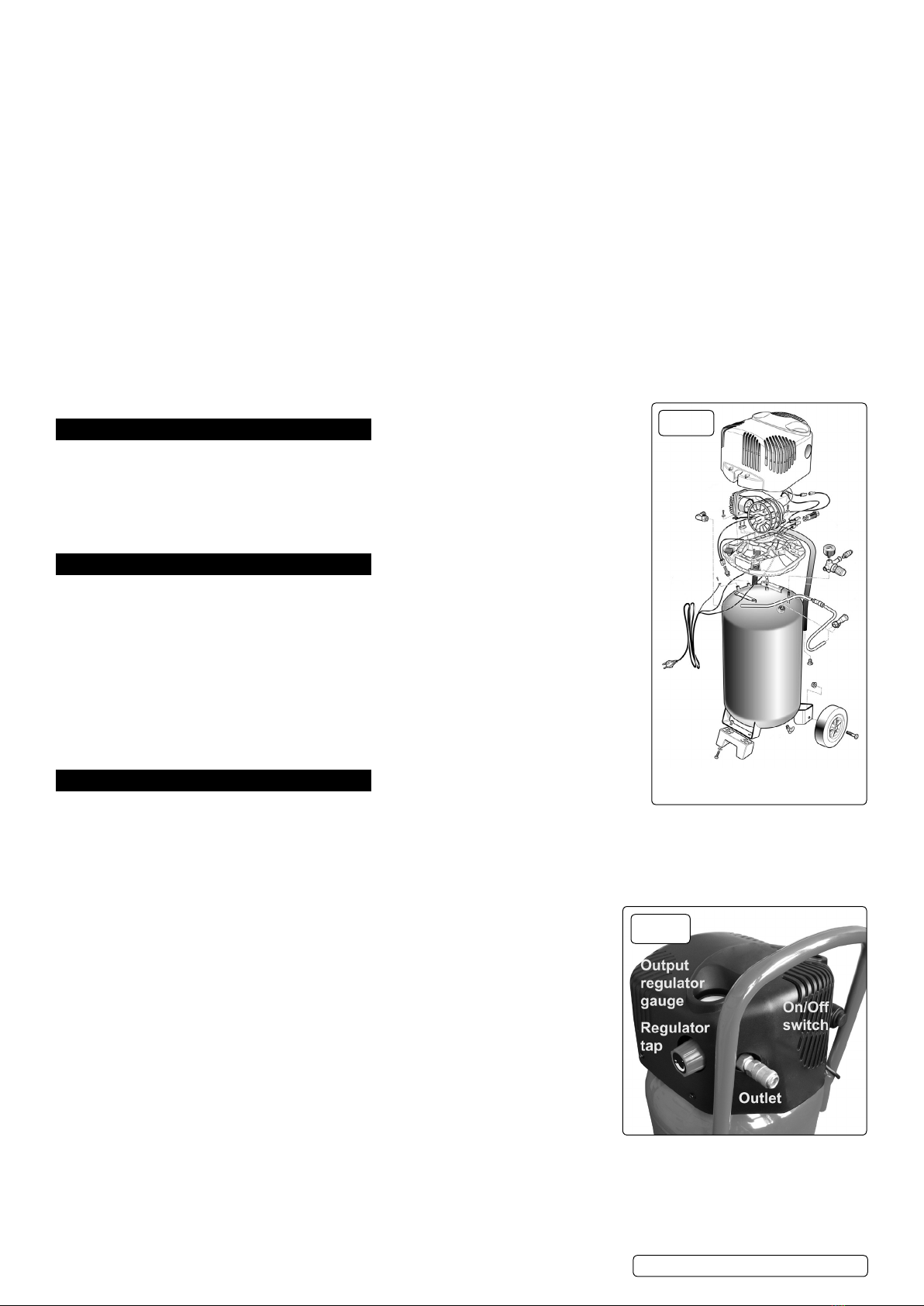
4.2.1. The compressor is tted with a push ON/OFF switch (g.2).
4.2.2. To turn the compressor ‘ON’ push the switch. To turn the compressor ‘OFF’ push the
switch again.
4.2.3. Check that the ON/OFF switch is in the “OFF” position and the regulator tap (g.2) is
closed (Zero ‘0’ bar, Anti-clockwise).
4.2.4. Plug mains lead into mains supply and start the compressor by pushing the ON/OFF switch.
4.2.5. Leave the compressor running with the regulator tap (fig.2) set to maximum pressure.
Make sure that the pressure in the tank rises and that the compressor stops automatically
when the maximum pressure value allowed - written on the specification plate is achieved.
The compressor will now operate automatically.
4.2.6. The pressure switch stops the motor when the maximum tank pressure is reached, and will
restart it when pressure falls below the minimum threshold - approx. 2 bar (29psi) less than
the maximum pressure.
4.2.7. Stop the compressor by pushing the ON/OFF switch (g.2). The compressed air inside the compressor head will flow out, making the
restart easier and preventing the motor from being damaged.
8DO NOT, other than in an emergency, stop the compressor by switching off the mains socket, or by pulling the plug out of the socket,
as the pressure relief will not then occur and motor damage may result upon restart.
fig.1
fig.2
SAC05020 | Issue:3 (H,F) 01/08/19
4.2.8. The output pressure is regulated by the pressure regulator tap (fig.2). Turn the tap clockwise to increase pressure and anti-clockwise to
reduce it, view the result on the output regulator gauge (fig.2).
NOTE: a) If the motor does not cut in and out, but runs continuously when using an air appliance, the capacity of the compressor may
be too small for the equipment or tool.
b) Should the pressure in the main tank exceed the pre-set switch maximum, the safety valve (located under the motor cowling
adjacent to the regulator gauge) will activate.
WARNING! For this reason DO NOT tamper with, or adjust, the pre-set switch or safety valve.
5. MAINTENANCE
In order to keep the compressor in good working condition, periodic maintenance is essential.
WARNING! Before performing any maintenance operation, switch off the compressor, disconnect from electrical supply and release all
air from the tank.
IMPORTANT! Failure to carry out maintenance tasks may invalidate the warranty on your compressor.
5.1. OPERATIONS TO BE CARRIED OUT AFTER THE FIRST 5 WORKING HOURS:
a) Check that all nuts/bolts are tight, particularly those retaining the crankcase and cylinder heads.
5.2. OPERATIONS TO BE CARRIED OUT DAILY:
a) Drain condensation by opening the valve located under the tank (g.4). Place a container under the valve to collect any
condensation.
Tip the compressor slightly towards the drain valve to ensure all condensation drains. Close valve after draining condensation and
dispose of it safely.
b) Regularly clean dirt and dust away from the safety devices with a clean cloth or blowing with low pressure compressed air.
Generally keep the compressor clean.
5.3. OPERATIONS TO BE CARRIED OUT EVERY 100 HOURS:
(Or more frequently, if the compressor operates in a very dusty atmosphere)
CLEAN AIR FILTER
a) Ensure the power is off and the tank has been vented. Remove the cowling from the motor by removing the four retaining screws.
NOTE! When removing the cowling, care should be taken not to inadvertently disconnect the wires from the switch.
b) Remove the lter element by pulling the lter cover from the housing (g.3).
Clean and replace the lter element. Snap the cover back into place.
5.4. OPERATIONS TO BE CARRIED OUT EVERY 200 HOURS:
a) Check the automatic cut-out at maximum pressure and the automatic cut-in at 2 bar below maximum pressure.
b) Replace air lter.
5.5. OPERATIONS TO BE CARRIED OUT EVERY 400 HOURS:
a) Check all ttings and electrical connections.
b) Inspect pressure tank inside and out for damage or corrosion.
5.6. SCHEDULED MAINTENANCE TABLE
.
Original Language Version
© Jack Sealey Limited
fig.3
Maintenance
Operations
Daily 100 hrs. 200 hrs. 400 hrs.
Drain condensation
•
Clean intake filter
•
General cleaning of compressor
•
Internal & external inspection of
tank
•
Replace air filter
•
Check tube fittings and electrical
connections
•
fig.4 1
2
SAC05020 | Issue:3 (H,F) 01/08/19
fig.5
Sealey Group, Kempson Way, Suffolk Business Park, Bury St Edmunds, Suffolk. IP32 7AR
01284 757500 01284 703534 sales@sealey.co.uk www.sealey.co.uk
ENVIRONMENT PROTECTION
Recycle unwanted materials instead of disposing of them as waste. All tools, accessories and packaging should be sorted, taken to
a recycling centre and disposed of in a manner which is compatible with the environment. When the product becomes completely
unserviceable and requires disposal, drain any fluids (if applicable) into approved containers and dispose of the product and fluids
according to local regulations.
Note: It is our policy to continually improve products and as such we reserve the right to alter data, specifications and component parts without prior
notice.
Important: No Liability is accepted for incorrect use of this product.
Warranty: Guarantee is 12 months from purchase date, proof of which is required for any claim.
WEEE REGULATIONS
Dispose of this product at the end of its working life in compliance with the EU Directive on Waste Electrical and Electronic Equipment
(WEEE). When the product is no longer required, it must be disposed of in an environmentally protective way. Contact your local solid
waste authority for recycling information.
6. TROUBLESHOOTING
SAC05020 | Issue:3 (H,F) 01/08/19
Original Language Version
© Jack Sealey Limited
Fault Cause Remedy
Pressure drop in the tank. Air leaks at connections.
Run compressor to max. pressure, switch off
unit. Brush soap solution over connections
and look for bubbles. Tighten connections
showing leaks.
If problem persists contact Authorised
Service Agent.
Pressure switch valve leaks when
compressor is idle. Non-return valve seal defective.
Empty the air tank, remove the non-return
valve cap (fig.5.2) and clean, or if necessary,
replace the seal (fig.5.1). Located under
motor cowling.
Compressor stops and does not restart. Motor failure. Contact Authorised Service Agent.
Compressor does not stop at max. pressure.
Pressure switch fault. Contact Authorised Service Agent.
Head gasket or valve fault. Contact Authorised Service Agent.
Compressor noisy with metallic knock. Bearing or piston damage. Contact Authorised Service Agent.

This manual suits for next models

1

Other Sealey Air Compressor manuals

Sealey SAC5020E.V2 User manual

Sealey

Sealey SAC5020E.V2 User manual

Sealey MAC03 User manual

Sealey

Sealey MAC03 User manual

Sealey MAC1250.V2 User manual

Sealey

Sealey MAC1250.V2 User manual

Sealey SAC3153B.V2 User manual

Sealey

Sealey SAC3153B.V2 User manual

Sealey SAC4505555B User manual

Sealey

Sealey SAC4505555B User manual

Sealey SACV52775B User manual

Sealey

Sealey SACV52775B User manual

Sealey RE225.V3 User manual

Sealey

Sealey RE225.V3 User manual

Sealey SAC42055B User manual

Sealey

Sealey SAC42055B User manual

Sealey SAC05020.V2 User manual

Sealey

Sealey SAC05020.V2 User manual

Sealey SAC1903B User manual

Sealey

Sealey SAC1903B User manual

Sealey SAC2420E110V.V2 User manual

Sealey

Sealey SAC2420E110V.V2 User manual

Sealey SAC0610E.V3 User manual

Sealey

Sealey SAC0610E.V3 User manual

Sealey SAC1903B User manual

Sealey

Sealey SAC1903B User manual

Sealey SAC03224 User manual

Sealey

Sealey SAC03224 User manual

Sealey Professional AB900 User manual

Sealey

Sealey Professional AB900 User manual

Sealey SA22420 User manual

Sealey

Sealey SA22420 User manual

Sealey Power PRODUCTS SAC89025VLN User manual

Sealey

Sealey Power PRODUCTS SAC89025VLN User manual

Sealey SAC3153B User manual

Sealey

Sealey SAC3153B User manual

Sealey SAC2276B.V2 User manual

Sealey

Sealey SAC2276B.V2 User manual

Sealey SAC55075B User manual

Sealey

Sealey SAC55075B User manual

Sealey SAC5030VE.V3 User manual

Sealey

Sealey SAC5030VE.V3 User manual

Sealey SAC2103B.V2 User manual

Sealey

Sealey SAC2103B.V2 User manual

Sealey SA2010/3 User manual

Sealey

Sealey SA2010/3 User manual

Sealey MAC23250 User manual

Sealey

Sealey MAC23250 User manual

Popular Air Compressor manuals by other brands

Bostit CAP2045ST-OL Operation and maintenance manual

Bostit

Bostit CAP2045ST-OL Operation and maintenance manual

BENDIX BA-921 COMPRESSOR-STD-CLOSED ROOM installation instructions

BENDIX

BENDIX BA-921 COMPRESSOR-STD-CLOSED ROOM installation instructions

Superex 50-174 instruction manual

Superex

Superex 50-174 instruction manual

Craftsman 919.724110 owner's manual

Craftsman

Craftsman 919.724110 owner's manual

Campbell Hausfeld Reference Design operating instructions

Campbell Hausfeld

Campbell Hausfeld Reference Design operating instructions

Doosan C185 Operation manual

Doosan

Doosan C185 Operation manual

SNOWJOE sunjoe 24V-AJC-MAX Operator's manual

SNOWJOE

SNOWJOE sunjoe 24V-AJC-MAX Operator's manual

Craftsman 919.152350 owner's manual

Craftsman

Craftsman 919.152350 owner's manual

Rac MV016 manual

Rac

Rac MV016 manual

Lenhardt & Wagner LW 320 E MC operating instructions

Lenhardt & Wagner

Lenhardt & Wagner LW 320 E MC operating instructions

Hydrovane V04 PUAS Series Service manual

Hydrovane

Hydrovane V04 PUAS Series Service manual

ARB CKMTA12 installation guide

ARB

ARB CKMTA12 installation guide

Buzzaudio SOC 1.1 Stereo Optical Compressor user manual

Buzzaudio

Buzzaudio SOC 1.1 Stereo Optical Compressor user manual

Vixen Air VXO4852DB manual

Vixen Air

Vixen Air VXO4852DB manual

Hyundai HY3200S user manual

Hyundai

Hyundai HY3200S user manual

ENKHO 151590.01 Original instructions

ENKHO

ENKHO 151590.01 Original instructions

QVC AirPro Faq

QVC

QVC AirPro Faq

VIAIR 50001 user manual

VIAIR

VIAIR 50001 user manual

manuals.online logo
manuals.online logoBrands
  • About & Mission
  • Contact us
  • Privacy Policy
  • Terms and Conditions

Copyright 2025 Manuals.Online. All Rights Reserved.