Humminbird IP Video Camera User manual

OVERVIEW
Use this guide to set up the IRIS402 Marine Network Camera on the Humminbird® control head network. We recommend that you read
this guide completely be ore starting the network setup.
Custo er Service: To purchase the Ethernet adapter cable, AS EC CHART cable, Ethernet Switch, extension cables, and
additional accessories, contact Humminbird Customer Service by visiting our Web site at hu inbird.co or by calling
1-800-633-1468.
NOTE: Product specifications and features are subject to change without notice.
Co patibility
The ONIX™and ION™control heads are compatible with the IRIS402 Marine Network
Camera. The ONIX control head displays video rom one camera source. The ION
control head allows you to display video rom our camera sources. Visit our Web site
at hu inbird.co or the latest accessories and updated compatibility in ormation
as additional cameras may be added to the network in the uture.
Preparation
Be ore the video camera is installed on the boat, it must be configured using a PC
with Internet access. We recommend using your home or office computer network
because a DHCP server is required or the configuration. Also, review the IRIS402
installation guide or the operating system, hardware installation, and power
requirements.
Configuration Supplies
In addition to the IRIS402 Marine Network Camera, you will need the ollowing supplies:
PC with Internet access (DHCP server required)
Networked router
Ethernet power injector or each camera
RJ45 cable or each Ethernet power injector
Power source (see the IRIS402 installation guide or hardware and voltage
requirements)
Installation Supplies
See Install the Camera(s on your Boat to determine the installation method you will
use. Also, re er to your IRIS402 installation guide or hardware and installation
requirements. In addition to the IRIS402 Marine Network Camera, you will need the
ollowing supplies:
Humminbird Ethernet adapter cable or each camera
OR
Ethernet power injector or each camera
Humminbird AS EC CHART cable or each Ethernet power injector
Optional Hu inbird Accessories: extension cables, Ethernet switches
1
532318-1_A
IP VIDEO CAMERA Setup Guide

2
532318-1_A
IP VIDEO CAMERA Setup Guide
1|Connect the Came a(s) to you Home/Office Netwo k
Be ore the camera is installed on the boat, it must be configured using a PC with Internet access. We recommend using your home
or office network or the configuration because a DHCP server must be used, which is a typical setup in a home/office network.
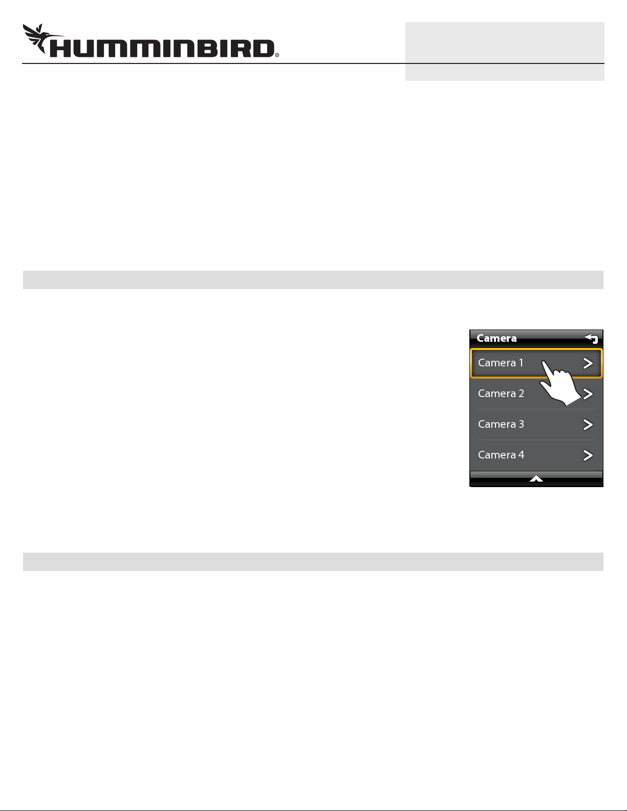
Assign Cameras 1 through 4
1. I you are installing more than one camera, designate each camera as Camera 1, Camera 2,
Camera 3, or Camera 4.
Connecting Camera(s) to a Home/Office Network (Overview)
Review the IRIS402 installation guide or power requirements and installation instructions. An overview
o the instructions is shown in this section.
1. Turn off the PC and power source.
2. Insert the IRIS RJ45 Ethernet cable connector into the Ethernet port on the camera. Hand
tighten the screw nut.
3. Insert the other end o the IRIS cable into the Power-Data Out port on the Ethernet power
injector.
If you are installing the Ethernet power injector, see the IRIS402 installation guide and the
Ethernet power injector guide to connect the Ethernet power injector to power. Use an
additional RJ45 cable to connect the power injector to the router or PC.
If an Ethernet power injector is not available, connect the IRIS RJ45 cable connector
(without the screw nut) to the Ethernet port on the router or PC. See your IRIS402 installation
guide to connect the cable wires to a power source.
If you are installing ore than one ca era, and a router with multiple ports is not available,
you can set up one camera at a time.
4. Turn on the computer.
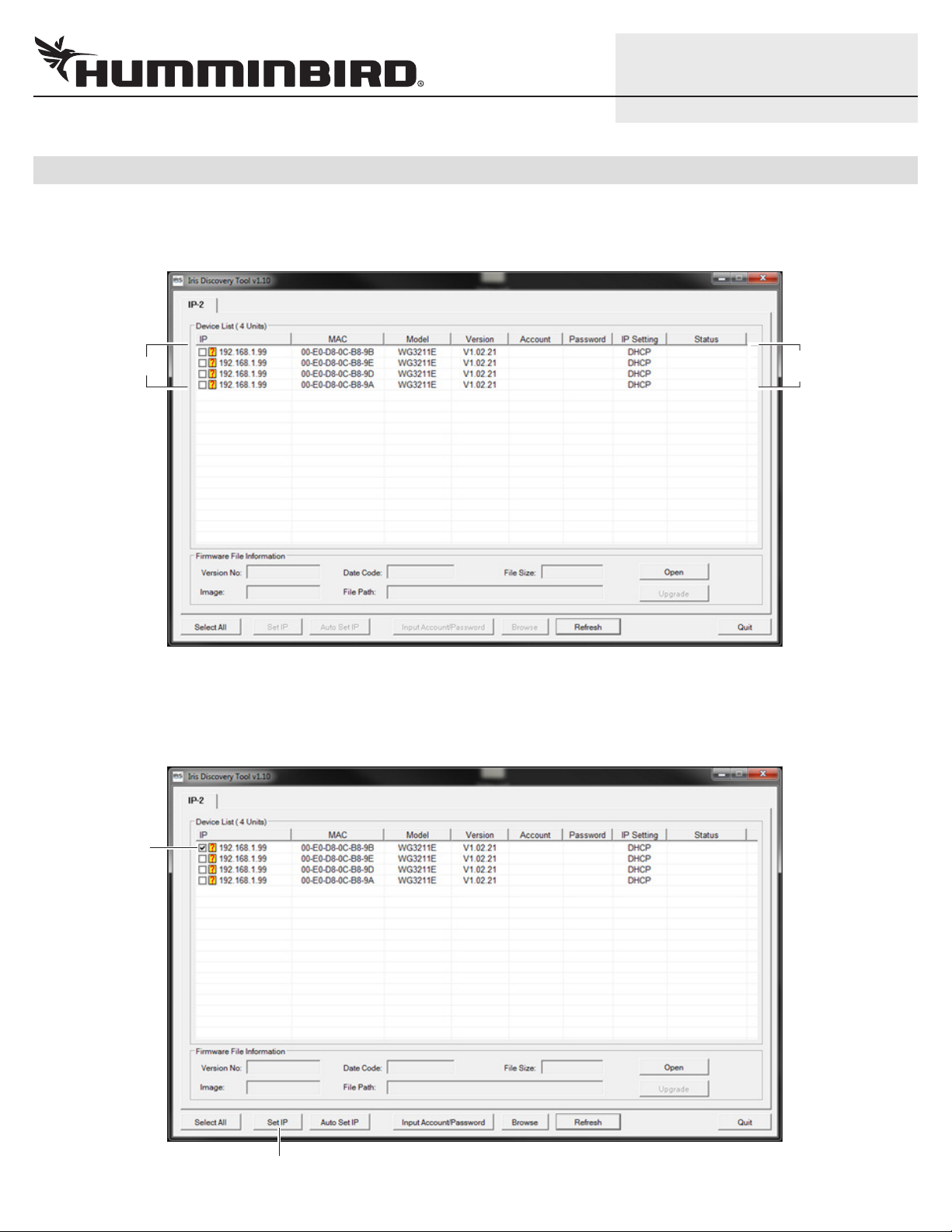
2|Download the IRIS Discove y Tool
Use the IRIS Discovery Tool to assign an IP address to the installed camera(s). The Discovery Tool can be downloaded rom your
Humminbird online account or rom the FAQ section o our Web site at hu inbird.co .
1. From your PC, go to our Web site at humminbird.com.
2. Select My Humminbird. Sign in to your Humminbird account.
OR
Select Support > Frequently Asked Questions, and search or IRIS Discovery Tool.
3. Select the IRIS Discovery Tool. Follow the on-screen prompts to download the file to your PC desktop.
3|Install the IRIS Discove y Tool
1. Double-click the IRIS Discovery Tool.exe file on your PC desktop.
2. Follow the on-screen prompts to install the IRIS Discovery Tool on your PC.
RJ45
connector
In erting the IRIS RJ45 Cable
Connector into the Camera Port
screw nut

4|Set up the Came a(s)
1. Double-click the IRIS Discovery Tool.exe file on your PC desktop to open it.
When you open the IRIS Discovery Tool, the connected cameras will be listed in the dialog box.
2. Click the first camera box to add a check mark to it.
3. Click Set IP.
Set IP
select the first
camera
camera list DHCP server
indication
3
532318-1_A
IP VIDEO CAMERA Setup Guide

4. Select the IP field, and enter the IP address or the selected camera as shown in the IP Address table.
5. Select the Gateway field, and enter the ollowing number: 169.254.0.1
NOTE: Do NOT change the Net Mask, Account, and Password.
6. Click OK.
7. Repeat steps 2 through 6 or each camera.
8. When you are finished setting up all cameras, click the Re resh button in the dialog box.
Review the camera list. I the cameras were set up correctly, the IP addresses will be listed in the IP column, and the IP Setting
will be displayed as Static.
IP Setting updated to Static
camera IP
addresses
updated
Refresh
Entering the IP Addre and Gateway
for Camera 1
IP Address: enter the IP
address for each camera.
The Gateway number is
the same for all cameras.
Ca era Nu ber IP Address
Ca era 1 169.254.200.1
Ca era 2 169.254.200.2
Ca era 3 169.254.200.3
Ca era 4 169.254.200.4
4
532318-1_A
IP VIDEO CAMERA Setup Guide

5
532318-1_A
IP VIDEO CAMERA Setup Guide
5|Configu e the St eam Settings
Use the instructions in this section to configure the stream settings or the selected camera. You will set up each camera individually.
1. Open your Internet Explorer (or other) browser on your PC.
2. In the address bar, enter the IP address or Camera 1. Press the Enter key.
The IRIS configuration tool will open.
3. Click Setup.
4. Click the Video Setting tab.
5. Click the drop-down arrow or Enable Stream 1.
Network
Setup
ideo Setting tab
Quality Level
drop-down menu
Configuring the Video Camera for Streaming
address bar
stream settings
Ca era Nu ber IP Address
Ca era 1 169.254.200.1
Ca era 2 169.254.200.2
Ca era 3 169.254.200.3
Ca era 4 169.254.200.4

6
532318-1_A
IP VIDEO CAMERA Setup Guide
6. Click the drop-down menus to set the ollowing streaming settings:
Resolution: 1280 x 720
Fra e Rate: 15 fps
Quality Level: Standard
7. Click Apply.
8. Proceed to the next section. Do not close the configuration tool.
6|Set the Multicast G oup Add ess
1. Click Network.
2. Click the Access Port tab.
3. Click the Always Multicast Stream 1 box to add a check mark to it.
Network Access Port tab
Enter the group
address for the
selected camera
according to the
Multicast Group
Address table
Setting the Multica t Group Addre
Click to add a
check mark to
Always
Multicast
Stream 1

7
532318-1_A
IP VIDEO CAMERA Setup Guide
4. Select the Multicast Group Address field, and enter the Multicast Group Address or the selected camera as shown in the
ollowing table.
5. Click Apply.
6. Click Live.
Confirm that live video rom the selected camera is displayed in the configuration tool on your PC.
I live video is not displayed, restore de aults (Setup > System > Maintenance), and repeat the instructions in this guide.
7. Repeat the instructions in Configure the Stream Settings and Set the Multicast Group Address or each camera.
8. Close your Internet browser and the Discovery Tool. Turn off the computer and remove the camera installation so it can be
installed on the boat.
7|Install the Came a(s) on you Boat
You can connect the camera(s) to the Humminbird control head network using an Ethernet power injector or using the Humminbird
Ethernet adapter cable. Re er to the section that applies to your installation configuration.
Also, review the IRIS402 installation guide or power requirements and installation instructions. I you’ve purchased an Ethernet power
injector separately, review the installation guide or instructions and requirements.
Connecting through an Ethernet Power Injector
1. Turn off the Humminbird control head network and main power switch.
2. Insert the IRIS RJ45 Ethernet cable connector into the Ethernet port on the camera. Hand
tighten the screw nut.
3. Insert the other end o the IRIS cable into the Power-Data Out port on the Ethernet power
injector.
4. Insert the AS EC CHART RJ45 Connector into the Lan-In port on the Ethernet power injector.
5. Connect the other end o the AS EC CHART cable to the Ethernet port on the control head or
the Ethernet Switch. Hand tighten the screw nut.
6. See the IRIS402 installation guide to connect power and finish the installation.
7. Repeat steps 2 through 6 to connect additional cameras.
RJ45
connector
In erting the IRIS RJ45 Cable
Connector into the Camera Port
screw nut
Ca era Nu ber Multicast Group Address
Ca era 1 239.128.1.99
Ca era 2 239.128.1.100
Ca era 3 239.128.1.101
Ca era 4 239.128.1.102

8
532318-1_A
IP VIDEO CAMERA Setup Guide
Connecting through the Ethernet Adapter Cable
1. Turn off the Humminbird control head network and main power switch.
2. Insert the IRIS RJ45 Ethernet cable connector into the Ethernet port on the camera. Hand tighten the screw nut.
3. Insert the other end o the IRIS cable into the Ethernet port on the adapter cable.
4. Connect the other end o the adapter cable to the Ethernet port on the control head or the Ethernet Switch. Hand tighten the
screw nut.
5. See the IRIS402 installation guide to connect the IRIS cable wires to power and finish the installation.
6. Repeat steps 2 through 5 to connect additional cameras.
8|Display the Video Came a St eam on the Cont ol Head
1. Power on the Humminbird control head network.
2. When the first view is displayed on the control head screen, press the HOME key.
3. Select Views.
4. Select Video.
5. Select a ull-screen Video View or a multi-pane view. The streaming video rom Camera 1 will
be displayed on-screen.
If you have ultiple video ca eras installed, press the MENU key. Select Camera. Select
the next camera in the menu (Camera 1, 2, 3, or 4) and confirm each camera is displayed.
If you have ultiple control heads installed, repeat the steps in this section to check the
Video View on each control head.
If a ca era is not detected on the network, restart the control head network and check the
Video View again. Also, see Review Camera Configuration on the Control Head or additional
in ormation. I the camera still doesn’t display, check all hardware connections and review the
settings in the IRIS Discovery Tool.
9|Review Came a Configu ation on the Cont ol Head (optional)
The instructions in this section are optional and allow you to change which video camera is assigned as the Camera 1, Camera 2,
Camera 3, or Camera 4 source in the control head. You can also use these instructions to review the camera configuration and IP
address.
1. Press the HOME key.
2. Select Settings > Network.
3. Under Source Settings, select Data Sources.
4. Under Video, select a Camera.
When Auto-Configure is turned on, the control head automatically assigns a video camera to display as Camera 1, 2, 3, or 4.
To change the ca era source assign ent, turn off Auto-Configure. Select a camera rom the list.
Selecting a Camera from
the X-Pre Menu

9
532318-1_A
IP VIDEO CAMERA Setup Guide
CONTACT HUMMINBIRD
Contact Humminbird Customer Service in any o the ollowing ways:
Web site humminbird.com
E-mail [email protected]
Telephone 1-800-633-1468
Direct Shipping Humminbird
Service Department
678 Humminbird Lane
Eu aula, AL 36027 USA
Humminbird®, ION™, ONIX™, and X-Press™ Menu are trademarked by or registered trademarks o Johnson Outdoors Marine Electronics, Inc.
IRIS is a registered trademark o Iris Innovations Limited.
© 2014 Johnson Outdoo s Ma ine Elect onics, Inc. All ights ese ved.
Camera 1 Source Auto-Configured (ION Control Head)
When Auto-
Configure is
turned on, the
control head
automatically
assigns a camera
to display as
Camera 1, 2, 3, 4.
.1 IP address =
Camera 1 Source
Camera (1) is selected
This manual suits for next models
1