THANK YOU!
Tank you for c oosing Humminbird®, t e #1 name in marine electronics. Humminbird as built its reputation by designing and
manufacturing top quality, t oroug ly reliable marine equipment. Your Humminbird is designed for trouble-free use in even t e
ars est marine environment. We encourage you to read t is manual carefully in order to get t e full benefit from all t e features
and applications of your Humminbird product.
Contact Humminbird Customer Service at humm nb rd.com or call 1-800-633-1468.
IMPORTANT INFORMATION
WARNING! Humm nb rd recommends cert f ed nstallat on by a
Humm nb rd approved nstaller. Contact your Humm nb rd
dealer for further deta ls, and refer to the warranty nformat on
ncluded w th your product.
DANGER: MICROWAVE RADIATION HAZARD! The m crowave
energy rad ated by a radar antenna s harmful to humans,
espec ally to one’s eyes. Do NOT look at the scanner from close
range. Never look d rectly nto an open wavegu de or nto the
path of rad at on from an enclosed antenna. Make sure
personnel are clear of the scanner when t s powered on. Turn
off the radar whenever t s necessary to work on the antenna
un t or on other equ pment n the beam of the radar.
DANGER: MICROWAVE RADIATION HAZARD! Radar and other
rad o frequency rad at on can upset card ac pacemakers. If
someone w th a card ac pacemaker suspects abnormal
operat on, mmed ately turn off the equ pment and move the
person away from the antenna.
HIGH VOLTAGE WARNING! Dangerously h gh voltages are
present w th n the scanner un t. There are no nternal
connect ons or adjustments necessary for nstallat on. Do NOT
remove any covers or otherw se attempt to access nternal
components, unless spec f cally nstructed n the
documentat on prov ded. The cover should be removed only by
a qual f ed radar serv ce techn c an. Techn c ans must exerc se
extreme care when work ng ns de the un t.
WARNING! Th s product must be nstalled and operated n
accordance w th the nstruct ons prov ded. Fa lure to do so could
result n personal njury, damage to your vessel and/or poor
product performance.
CAUTION! Installat on and radar tun ng should only be
performed by a qual f ed radar serv ce techn c an.
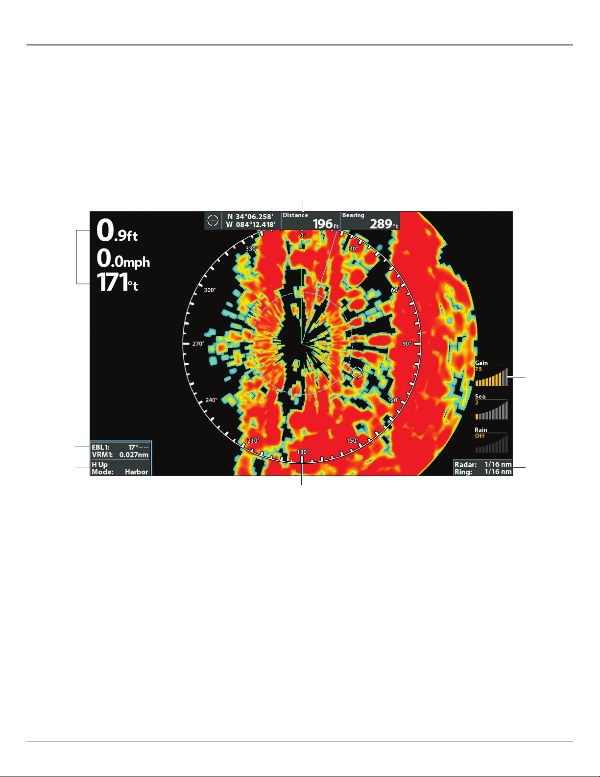
WARNING! How to nterpret the radar d splay s not ncluded n
th s manual. The capta n s respons ble for the proper use of
radar and the safety of the vessel and ts passengers.
WARNING! Th s dev ce should not be used as a nav gat onal a d
to prevent coll s on, ground ng, boat damage, or personal njury.
When the boat s mov ng, water depth may change too qu ckly to
allow t me for you to react. Always operate the boat at very slow
speeds f you suspect shallow water or submerged objects.
WARNING! The electron c chart n your Humm nb rd un t s an
a d to nav gat on des gned to fac l tate the use of author zed
government charts, not to replace them. Only off c al
government charts and not ces to mar ners conta n all of the
current nformat on needed for the safety of nav gat on, and the
capta n s respons ble for the r prudent use.
WARNING! Humm nb rd s not respons ble for the loss of data
f les (waypo nts, routes, tracks, groups, record ngs, etc.) that
may occur due to d rect or nd rect damage to the un t’s
hardware or software. It s mportant to back up your control
head’s data f les per od cally. Data f les should also be saved to
your PC before restor ng the control head defaults or updat ng
the software.
WARNING! D sassembly and repa r of th s electron c un t should
only be performed by author zed serv ce personnel. Any
mod ficat on of the ser al number or attempt to repa r the or g nal
equ pment or accessor es by unauthor zed nd v duals w ll vo d the
warranty.
WARNING! Th s product conta ns chem cals known to the State of
Cal forn a to cause cancer and b rth defects or other reproduct ve
harm.
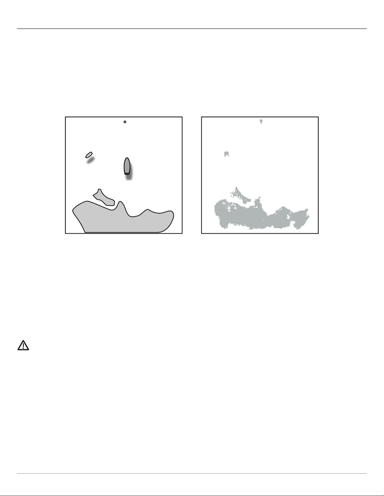
NOTE: The llustrat ons n th s manual may not look the same as
your product, but your un t w ll funct on n a s m lar way.
NOTE: The procedures and features descr bed n th s manual are
subject to change w thout not ce. Th s manual was wr tten n
Engl sh and may have been translated to another language.
Humm nb rd s not respons ble for ncorrect translat ons or
d screpanc es between documents.
NOTE: Product spec f cat ons and features are subject to change
w thout not ce.
NOTE: For nstallat on nformat on, see the nstallat on manual
ncluded w th your product.
NOTE: Th s product s spec f cally des gned to be nstalled on
boats and other means of mar t me transport. If your country
forms part of the EU, please contact your dealer for adv ce
before attempt ng to nstall elsewhere.
2