JRC JMR-5404-X User manual

ISO 9001, ISO 14001 Certified
OCT. 2021 Edition 6CODE No.7ZPRD0955
MARINE RADARMARINE RADAR
EQUIPMENTEQUIPMENT
JMRJMR-54045404-X
JMRJMR-54065406-X
JMRJMR-54105410-4X/4XH/6X/6XH4X/4XH/6X/6XH
JMRJMR-54255425-6XH/7X/9X6XH/7X/9X
JMRJMR-54305430-S
JMRJMR-54725472-S
JMRJMR-54825482-S/SHS/SH
Not use the asbestos
For further information,contact:
URL Head office : http://www.jrc.co.jp/eng/
Marine Service Department
1-7-32 Tatsumi, Koto-ku, Tokyo 135-0053, Japan
:
+81-50-3786-9201
e-mail
One-call
SIMPLIFIEDSIMPLIFIED
INSTRUCTIONINSTRUCTION
MANUALMANUAL


㻌
㻌
㻌(1) Contents
2
3
4
5
6
7
8
9
10
11
12
13
14
15
16
17
18
19
20
21
22
23
24
25
26
27
Contents
Section 1 Introduction ................................................................................... 1-1
1.1 Read Before Use................................................................................................................... 1-1
Section 2 Basic Operation ............................................................................ 2-1
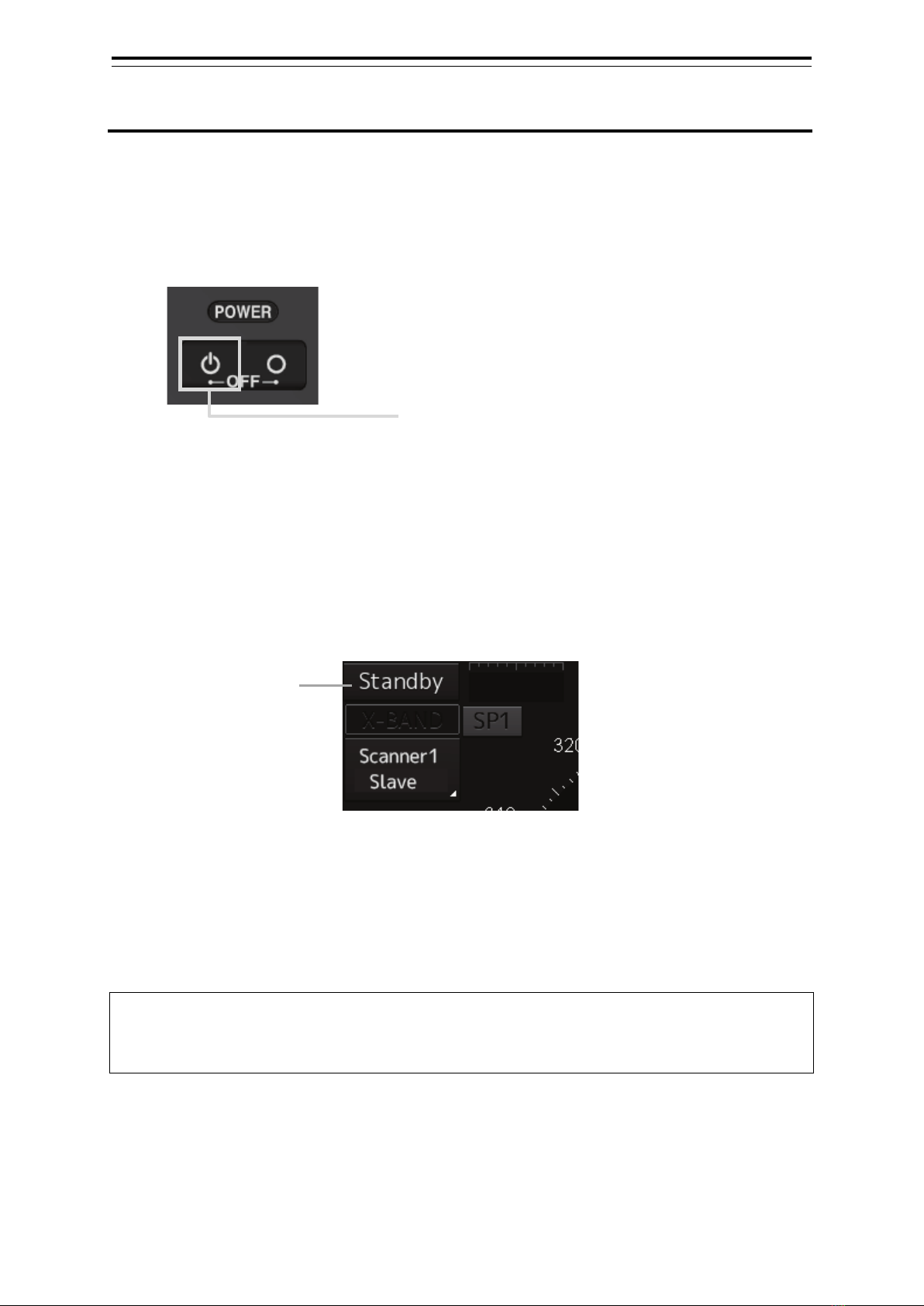
2.1 Powering On and Starting..................................................................................................... 2-1
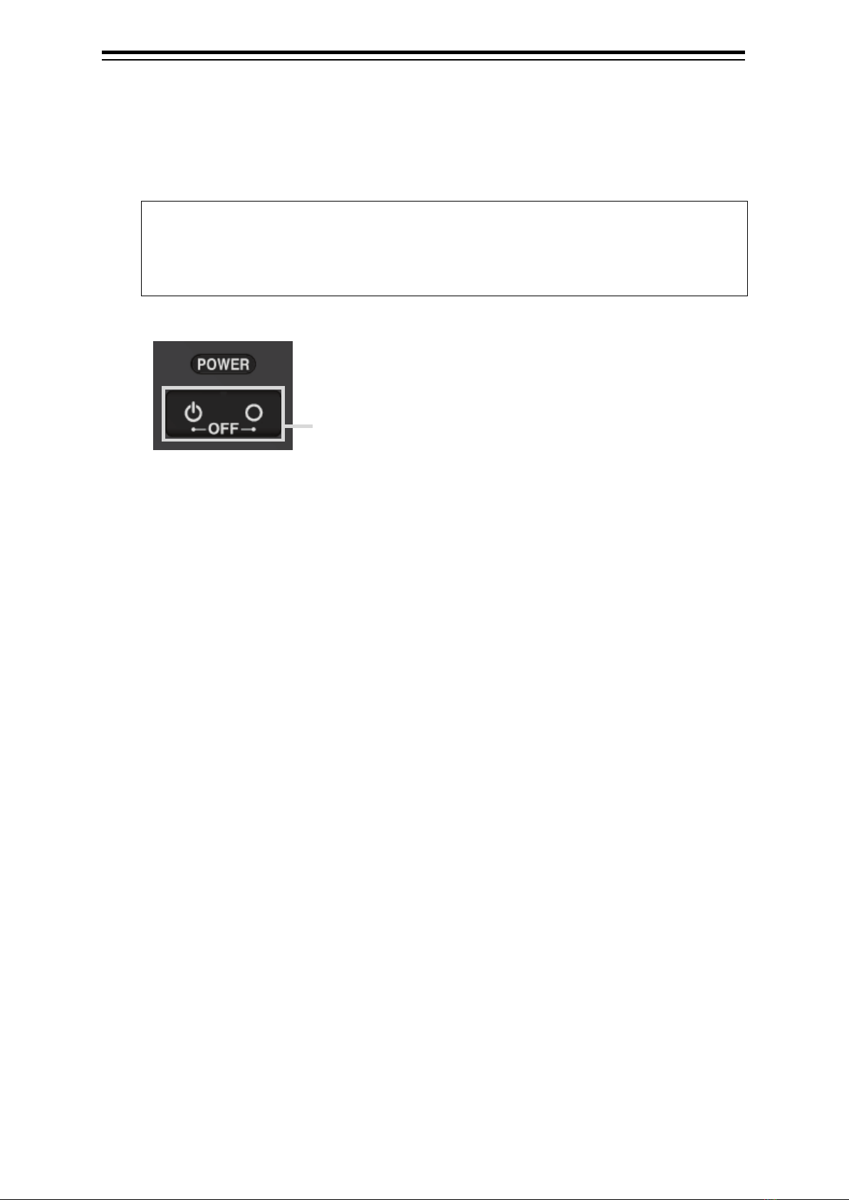
2.2 Finishing and Stopping Operation......................................................................................... 2-2
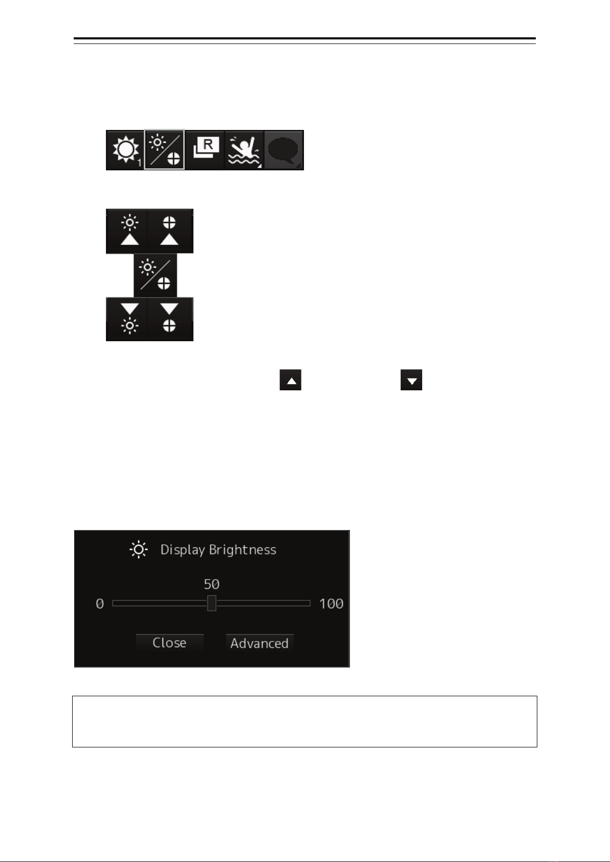
2.3 Adjusting Screen Brightness................................................................................................. 2-3
2.3.1 Adjust the screen using the right tool bar ..................................................................... 2-3
2.3.2 Adjust the screen using the [MULTI] dial. ..................................................................... 2-3
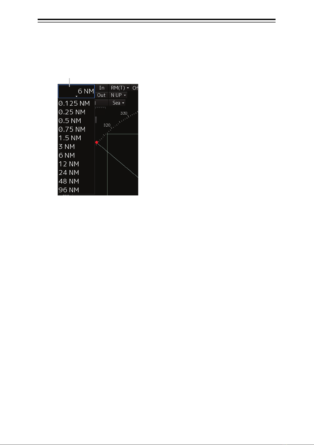
2.4 Changing the Observation Range......................................................................................... 2-4
2.5 Adjusting Gain....................................................................................................................... 2-5
2.6 Removing Sea Clutters ......................................................................................................... 2-6
2.7 Removing Rain/Snow Clutters .............................................................................................. 2-8
2.8 Using the Electronic Bearing Line(EBL) and Variable Range Marker(VRM) ...................... 2-10
2.8.1 Measuring a range and a bearing with EBL and VRM ............................................... 2-10
2.8.2 Measuring between arbitrary two points..................................................................... 2-11
2.9 Switching the Transmission Pulse Length .......................................................................... 2-12
2.10 Switching the Azimuth Mode............................................................................................... 2-13
2.11 Switching the Motion Mode ................................................................................................. 2-14
2.11.1 Resetting own ship to its initial position in [TM] (True Motion display) mode ............. 2-15
2.12 Displaying Radar Trail......................................................................................................... 2-16
2.12.1 Changing the trail length............................................................................................. 2-16
2.12.2 Erasing a radar trail..................................................................................................... 2-16
2.12.3 Changing the display mode of radar trails .................................................................. 2-17
Section 3
Operation of Target Tracking
...................................................................... 3-1
3.1 Acquiring a Target ................................................................................................................. 3-1
3.1.1 Auto acquisition (automatic acquisition) mode ............................................................. 3-1
3.1.2 ACQ MANUAL (manual acquisition) mode................................................................... 3-2
3.1.3 Using manual acquisition and auto acquisition together .............................................. 3-2
3.2 Displaying the Information of Tracking Targets ..................................................................... 3-3
3.3 Erased Tracked Targets ........................................................................................................ 3-4
Section 4 AIS Operation ................................................................................ 4-1
4.1 Setting Up the AIS Display Function ..................................................................................... 4-1
4.2 Activating an AIS Target ........................................................................................................ 4-2
4.2.1 Manual activation.......................................................................................................... 4-2
4.2.2 Automatic activation...................................................................................................... 4-2
4.3 Displaying the AIS Information.............................................................................................. 4-3
7ZPRD0955

Contents (2)
4.4 Deactivating an AIS Target.................................................................................................... 4-4
Section 5 Operation Common to Target Tracking and AIS......................... 5-1
5.1 Setting Up Vectors ................................................................................................................ 5-1
5.1.1 Setting up the vector mode........................................................................................... 5-1
5.1.2 Setting up the vector length .......................................................................................... 5-1
5.2 Setting Up the Collision Determining Condition.................................................................... 5-2
5.2.1 Setting up the CPA limit ................................................................................................ 5-2
5.2.2 Setting up the TCPA limit .............................................................................................. 5-2
Section 6 Other Operations .......................................................................... 6-1
6.1 Stopping an Alert................................................................................................................... 6-1
6.2 Acknowledging an Alert......................................................................................................... 6-2
6.3 Operation with the Software Keyboard ................................................................................. 6-3

1-1 Section 1 Introduction
1
2
3
4
5
6
7
8
9
10
11
12
13
14
15
16
17
18
19
20
21
22
23
24
25
26
27
付録
Section 1 Introduction
1.1 Read Before Use
About the Quick Operation Guide
For more details, please read the Operation Manual.
Please keep this Quick Operation Guide in an easily accessible place.
About the Radar
Use the radar solely as a navigation aid. Also, the final decision of manoeuvring must be made by the
person who manoeuvres the ship. If the final decision on manoeuvring is solely made based on the
information displayed by the radar, it may cause accidents such as collision and running aground.
About sea clutter suppression
Do not adjust the sea clutter suppression function until all sea clutters are erased in the close distance
range.
Otherwise, targets such as vessels and dangerous objects will be suppressed in addition to echoes
from waves, causing to interfere detection.
When using the sea clutter suppression function, always perform optimum suppression adjustment.
About rain/snow clutter suppression
Do not adjust the rain/snow suppression function excessively. Otherwise, targets such as vessels and
dangerous objects will be suppressed in addition to echoes from rain and snow, causing to interfere
detection.
When using the rain/snow clutter suppression function, always perform optimum suppression
adjustment.
About the target tracking function
Use the target tracking function solely as a navigation aid. Also, the final decision of manoeuvring must
be made by the person who manoeuvres the ship. If the final decision on manoeuvring is solely made
based on the information acquired from the target tracking function, it may cause accidents.
Vectors, target numeric data, alarms and other information displayed by the target tracking function
may contain errors. Note that targets which cannot be detected by the radar can neither be acquired
nor tracked.
If the final decision on manoeuvring is solely made based on the information displayed by the radar, it
may cause accidents such as collision and running aground.


2-1 Section 2 Basic Operation
1
2
3
4
5
6
7
8
9
10
11
12
13
14
15
16
17
18
19
20
21
22
23
24
25
APP A
APP B
1
Section 2 Basic Operation
2.1 Powering On and Starting
1 Check that the ship’s mains are turned on.
2 Press the Power button on the operation unit.
Start-up screen is displayed.
After the start-up screen is displayed, the Mode Selection screen is displayed after a brief
interval.
3 Click on the [RADAR] button on the Mode Selection screen.
The RADAR screen appears.
The preheating time is displayed at the centre of the screen.
When the magnetron radar antenna is connected, “Preheat” is displayed on the Standby/Send
switching button.
4 Wait until preheating is complete.
When the preheating time expires, the preheating time display disappears, and the display of
the Standby/Transmit switch button changes from "Preheat" to "Standby".
5 Click on the Standby/Transmit switch button.
Radar transmission starts and the radar antenna rotates.
The display of the Standby/Transmit switch button changes from "Standby" to "Transmit".
Memo
Even if the Standby/Transmit switch button is clicked on while "Preheat" is being displayed, radar
transmission cannot be performed.
Standby/transmission
changeover button
Power button

Section 2 Basic Operation 2-2
2.2 Finishing and Stopping Operation
1 Click on the Standby/Transmit switch button in Radar system information.
Radar transmission stops and the rotation of the radar antenna stops.
The display of the Standby/Transmit switch button changes from "Transmit" to "Standby".
Memo
If observation using the radar is being scheduled within a comparably short period of time,
keep this state. Observation can be started immediately by just
clicking on the
Standby/Transmit switch button.
2 Press the Power button on the operation unit.
The power to this equipment is turned OFF.
Power button
Please press the 2 keys
simultaneously.

2-3 Section 2 Basic Operation
1
2
3
4
5
6
7
8
9
10
11
12
13
14
15
16
17
18
19
20
21
22
23
24
25
APP A
APP B
1
2.3 Adjusting Screen Brightness
2.3.1 Adjust the screen using the right tool bar
1 Click on the [Display and Panel Brightness] button on the right toolbar.
The brightness adjustment buttons of the screen and the operation unit are displayed.
Adjust the brightness of the screen on the left side.
2 Adjust the brightness by using the [Light] button and [Dark] button.
Whenever the [Light] button/[Dark] button is clicked on, the brightness changes by one level.
2.3.2 Adjust the screen using the [MULTI] dial.
If the [MULTI] dial is operated while [Display Brightness] function is selected as the [MULTI] dial
assignment function, the [Display Brightness] dialogue is displayed.
It is possible to adjust the brightness of the display section by rotating the [MULTI] dial.
Memo
When "DISP Brightness" is not being displayed in the Key Assignment Indication Area, press the
[MULTI] dial for a long time.The Display Brightness function will be assigned to the [MULTI] dial.

Section 2 Basic Operation 2-4
2.4 Changing the Observation Range
1 Click on the [Range Scale] button in Range and mode information and select a range
from the context menu.
[Points on adjustments]
Increasing the observation range will enable a wider range to be observed.
However, a video image is small and the ability to detect targets near own ship decreases.
Therefore, when observing the vicinity of own ship, use the smaller observation range.
Decreasing the observation range will enable the vicinity of own ship to be enlarged. However,
caution must be taken because video images of the area beyond the observation range cannot
be displayed.
Range Scale button

2-5 Section 2 Basic Operation
1
2
3
4
5
6
7
8
9
10
11
12
13
14
15
16
17
18
19
20
21
22
23
24
25
APP A
APP B
1
2.5 Adjusting Gain
1 Drag the [Gain] (reception gain adjustment) slider dial in Radar signal information,
turn the trackball, and set up reception gain.
Moving the slider to the right increases gain.
Moving the slider to the left decreases gain.
The current reception gain level is indicated by the bar and a numeric value.
[Points on adjustments]
As reception gain is increased, the range in which radar images can be observed widens; however, if
gain is increased too high, receiver noise, false echoes and other undesired signals will increase on
the screen, lowering the visibility of targets.
Also, it gets easier to see the screen display if gain is decreased to observe cluttered targets and close
range, but be careful not to overlook small targets.
Current reception gain
[Gain] (reception gain adjustment) slider

Section 2 Basic Operation 2-6
2.6 Removing Sea Clutters
1 Drag the [Sea] (sea clutter adjustment) slider dial in Radar signal information, turn the
trackball, and adjust the amount of images by sea clutter displayed on the screen so
as to make display easy to observe.
Moving the slider to the right decreases the amount of images by sea clutter.
Moving the slider to the left increases the amount of images by sea clutter.
The current level of sea clutter suppression is indicated by the bar and a numeric value.
[Points on adjustments]
The sea clutter suppression function decreases the amount of images by sea clutter by lowering
reception gain at close range. When reception gain is lowered, the effectiveness of sea clutter
suppression increases; however, if excessive effect is applied, please note that targets having weak
signal strength such as buoys and small ships will disappear.
Using the function of automatic sea clutter suppression mode
The sea clutter suppression in accordance with the intensity of sea clutter is possible. Use this mode
when the sea clutter's intensity differs according to directional orientation.
1 Click on the Automatic Sea Clutter Suppression button.
[AUTO] (automatic) is displayed on the automatic sea clutter suppression button.
Each time this button is clicked on, the display switches between [AUTO] (automatic) and
[MAN] (manual).
2 Drag the sea clutter adjustment slider dial, turn the trackball, and adjust the amount of
images by sea clutter displayed on the screen.
Even while automatic sea clutter is being suppressed, the amount of images can be
fine-adjusted manually.
Auto Sea Clutter Suppression button
Current level of sea clutter suppression
[Sea] (sea clutter adjustment) slider

2-7 Section 2 Basic Operation
1
2
3
4
5
6
7
8
9
10
11
12
13
14
15
16
17
18
19
20
21
22
23
24
25
APP A
APP B
1
Canceling automatic sea clutter suppression
1 Click on the Automatic Sea Clutter Suppression button.
[MAN] (manual) is displayed on the automatic sea clutter suppression button.
Each time this button is clicked on, the display switches between [AUTO] (automatic) and
[MAN] (manual).

Section 2 Basic Operation 2-8
2.7 Removing Rain/Snow Clutters
1 Drag the [Rain] rain/snow clutter adjustment slider dial in Radar signal information,
turn the trackball, and adjust the amount of images by rain/snow clutter displayed on
the screen so as to make display easy to observe.
Moving the slider to the right decreases the amount of images by rain/snow clutter.
Moving the slider to the left increases the amount of images by rain/snow clutter.
The current level of rain/snow clutter suppression is indicated by the bar and a numeric value.
[Points on adjustments]
When the amount of images by rain/snow clutter is decreased, the outlines of targets hidden by images
of rain/snow will appear, but please note that small targets may be missed. Since this can also reduce
sea clutter, it is effective to use it together with the sea clutter rejection function.
Normally, set the level of rain/snow clutter suppression to 0.
Current level of rain/snow clutter suppression
[Rain] (rain/snow clutter adjustment) slider

2-9 Section 2 Basic Operation
1
2
3
4
5
6
7
8
9
10
11
12
13
14
15
16
17
18
19
20
21
22
23
24
25
APP A
APP B
1
Using the automatic rain/snow clutter suppression mode
The rain/snow clutter suppression in accordance with the intensity of rain/snow clutter is possible. Use
this mode when the rain/snow clutter's intensity differs according to directional orientation.
1 Click on the Automatic Rain/Snow Clutter Suppression button.
[AUTO] (automatic) is displayed on the automatic rain/snow clutter suppression
button.
Each time this button is clicked on, the display switches between [AUTO] (automatic) and
[MAN] (manual).
2 Click the left mouse button of the button on the [Rain] (rain/snow clutter adjustment)
slider, drag it with the trackball, and adjust the volume of the echo created by
rain/snow clutter that is displayed on the screen.
Even while auto rain/snow clutter is being suppressed, the amount of images can be
fine-adjusted manually.
Canceling automatic rain/snow clutter suppression
1 Click on the Automatic Rain/Snow Clutter Suppression button.
[MAN] (manual) is displayed on the automatic rain/snow clutter suppression button.
Each time this button is clicked on, the display switches between [AUTO] (automatic) and
[MAN] (manual).
Auto Rain/Snow Clutter Suppression button

Section 2 Basic Operation 2-10
2.8 Using the Electronic Bearing
Line(EBL) and Variable Range
Marker(VRM)
2.8.1 Measuring a range and a bearing with EBL
and VRM
This section describes the manipulation under EBL1 and VRM1; however, the same manipulation can
be performed under EBL2 and VRM2 also.
Memo
To manipulate the EBL/VRM, the RADAR transmission status must be “Transmit”.
1 Enable the manipulation of EBL1 by clicking on the [EBL1] button.
2 Enable the movement of EBL1 by clicking on the EBL1 line.
3 Align the cursor with a target and click on the mouse button.
The bearing of the target is displayed on the [EBL1] button.
4 Enable the manipulation of VRM1 by clicking on the [VRM1] button.
5 Enable the movement of VRM1 by clicking on the VRM1 circle.
6 Align the cursor with a target and click on the mouse button.
The range of the target is displayed on the [VRM1] button.
[EBL1] button
[VRM1] button

2-11 Section 2 Basic Operation
1
2
3
4
5
6
7
8
9
10
11
12
13
14
15
16
17
18
19
20
21
22
23
24
25
APP A
APP B
1
2.8.2 Measuring between arbitrary two points
Here, the manipulation with EBL2/VRM2 is explained. The same operation can be performed with
EBL1/VRM1.
Memo
To manipulate the EBL/VRM, the RADAR transmission status must be “Transmit”.
1 Click on the measurement starting point button of EBL2/VRM2 and select [D].
2 Align the cursor with “point A” of the two points to be measured and then click it on.
3 Enable the movement of EBL2 by clicking on the EBL2 line.
4 Align the cursor with bearing “point B” of the two points to be measured and then click
it on.
5 Enable the manipulation of VRM2 by clicking on the [VRM2] button.
6 Move the intersecting point marker on the dotted line of EBL2 by the cursor and align it
with point B.
The range and bearing between the two points are displayed.
Memo
The measurement reference point of this equipment’s EBL/VRM can be selected from the
following three types. Set up a measurement reference point according to usage.
• Blank(CCRP) : Sets a measurement reference point at own ship’s position (CCRP).
• C(Carried) : Fixes a measurement point on the screen.
• D(Dropped) : Fixes a measurement point with longitude and latitude.
Measurement starting point button
[VRM2] button

Section 2 Basic Operation 2-12
2.9 Switching the Transmission Pulse
Length
1 Click on the Transmitter Pulse Length switch button in radar signal information.
Each time this button is clicked on, the transmitter pulse length changes.
Transmitter
pulse length Functions and effects Recommended condition
for selection
[SP] •The transmitter pulse becomes shorter, and the
range resolution improves.
•The effect of suppressing sea clutter and
rain/snow clutter improves.
In bays/harbors where
targets are densely crowded
Rough sea state due to
torrential rain or stormy
weather
[MP]
•The normal transmitter pulse length is set.
•Both range resolution and gain are appropriately
set.
General navigation
[LP] •The transmitter pulse becomes longer, and gain
improves.
•Small targets are zoomed and are easy to
observe.
•When the sea state is bad, detection
performance decreases.
Detection of small targets in
good weather conditions
Example: [MP1] →[MP2] →[LP1] →[LP2]
Transmitter pulse length switch button.

2-13 Section 2 Basic Operation
1
2
3
4
5
6
7
8
9
10
11
12
13
14
15
16
17
18
19
20
21
22
23
24
25
APP A
APP B
1
2.10 Switching the Azimuth Mode
Set the bearing for the radar video to be displayed on the radar display.
1 Click on the azimuth mode combo box of Range and mode information.
2 Select the Azimuth mode.
The following azimuth modes can be set.
Setting items
Description
Display image
[N UP] North UP (North Up)
• The video is displayed so that the zenith of the PPI points to
the due north.
• Fixed targets do not flicker and are easily identified on the
chart, and the true bearing of a target can easily be read out.
[H UP] Head UP (Head Up)
• The video is displayed so that the ship’s heading line is
displayed at the top of the screen. Since targets are displayed
in their directions relative to the ship’s heading line, the
operator can view the video in the same field of view as in
operating the ship at sea. Therefore, This mode is suitable for
watching over other ships
• This is not available for TM (True Motion) mode.
[C UP] Course UP (Course Up)
• At the setting of Course Up, the ship’s heading (HDG) is fixed
and displayed immediately above the screen. Similar to true
bearing display, the positions of stationary targets will
not deviate even if yawing occurs in the ship: targets
are displayed stably and the bearing of the heading line
moves only according to the amount of change in own
ship's course. To change the course, select the Course
UP display by clicking on the Azimuth mode combo box
several times. A course can be set again.
[C UP (Angle
Setting)]
Course UP by angle setting (Course Up by angle setting)
• When C UP is selected, the [C UP (Angle Setting)] dialogue
box is displayed. The course angle that is set in the dialogue
box is displayed by being fixed at the top of the screen.
-Input the angle of the ship’s heading in the [Angle] input
box of the [C UP (Angle Setting)] dialogue box.
-The angle can also be input (increase/decrease) by
operating the angle input slider.
-
After completing the setting, click on the [X] button.
North
North
Azimuth Mode combo
box

Section 2 Basic Operation 2-14
2.11 Switching the Motion Mode
By setting a motion mode, the display method of the own ship’s position on the radar screen can be
changed.
Switching relative motion (RM) mode to true motion (TM) mode
1 Click on the Motion Mode combo box in Range and mode information.
2 Select the motion mode.
Memo
Available combinations vary depending on the settings of the motion mode and the
azimuth mode (refer to "2.10 Switching the Azimuth Mode").
Azimuth mode
Motion mode
N UP H UP C UP C UP
(Angle Setting)
TM
×
RM(T) or RM(R)
Motion Mode combo box
This manual suits for next models
12
Table of contents
Other JRC Marine Radar manuals

JRC
JRC 2000 Quick start guide

JRC
JRC JMR-92 Series Quick start guide

JRC
JRC JMA-5912-6 User manual

JRC
JRC JMA-7110-6XA User manual

JRC
JRC JMA-5212-4/6 User manual

JRC
JRC JMA-5212-4 User manual

JRC
JRC JMA-5208 User manual

JRC
JRC JMA-1032 User manual

JRC
JRC JMA-9832-SA User manual

JRC
JRC JMR-7230-S3 User guide

JRC
JRC JMA-922B-6XA User manual

JRC
JRC JUE-250 - Operator's manual

JRC
JRC JMA-5104 User manual

JRC
JRC JMA-7710-6 User manual

JRC
JRC JMA-9133-SA User manual

JRC
JRC JMA-5352-9R User manual

JRC
JRC JMA-3806 User manual

JRC
JRC JMR-5410-4X User manual

JRC
JRC JMA-3300 Series User manual

JRC
JRC JMA-3910-4 User manual