1. To install the charging station
1. Place the charging station on a flat level surface where there is open space.
NOTE: To place the charging station in a limited space or in a corner, please read
the Operator’s manual.
2. Connect the low voltage cable to the charging station and the power supply.
3. If outdoor, put the power supply at a minimum height of 30 cm / 12 in from the ground.
4. Connect the power supply to a 100-240 V wall socket.
5. Place the robotic lawn mower in the charging station.
6. Push the ON/OFF button to switch on the robotic lawn mower and to charge the battery
while the boundary wire is laid.
NOTE: Do not continue with any product settings before the installation is complete.
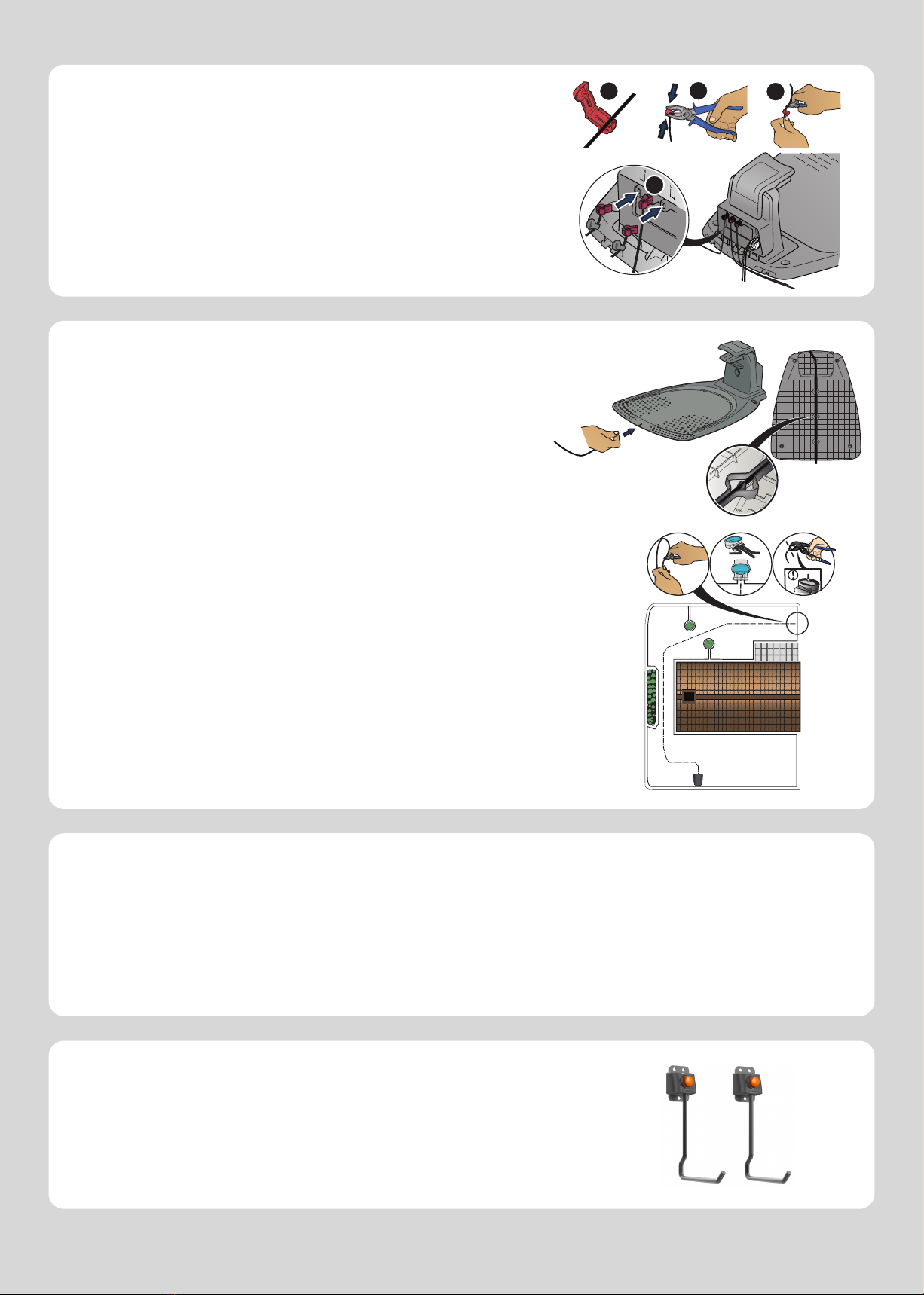
3. To connect the boundary wire
1. Open the connector and lay the boundary wire in the connector.
2. Press the connector and the wire together by using a pair of pliers.
3. Cut off the wire 1-2 cm / 0.4-0.8 in. after the connectors.
4. Press the boundary wire connectors onto the contact pins marked L (left) and R
(right) on the charging station.
NOTE: The right-hand wire must be connected to the right-hand contact pin on the
charging station, and the left-hand wire to the left-hand pin.
4. To install and connect the guide wire
Install a guide wire to lead the robotic lawn mower to remote parts of the lawn and to
help it to find the charging station.
1. Push the guide wire through the bottom of the charging station and fasten it into place
using the snap locks.
2. Fit the connector to the guide wire in the same way as for the boundary wire, according to
the instructions above.
3. Press the guide wire connector onto the contact pin marked GUIDE on the charging
station.
4. Pull the guide wire a minimum of 1 m / 3.3 ft. straight out from the front edge of the
charging station.
5. Lay the guide wire from the charging station to the point on the boundary wire (eyelet)
where the connection is made using stakes supplied or bury the wire.
NOTE: Do not lay the guide wire in sharp bends. The guide wire cannot cross the
boundary wire that for instance is laid out for an island.
6. Cut the boundary wire at the center of the eyelet that was made in step 2.3.
7. Connect the guide wire to the boundary wire by inserting the boundary wires and
guide wire in the coupler, and pressing the coupler together with a pair of pliers.
Make sure that the coupler is fully pressed together.
NOTE: After the guide wire is installed, attach the charging station to the ground with
the supplied screws and allen key.
NOTE: For optimal performance through narrow passages please ensure the gui-
de wire is laid correctly through it. Please read the Operator‘s manual for further
instructions.
To stop the product
1. Push the STOP button.
5. To start and stop the robotic lawn mower
To start the product
1. Push the ON/OFF button for 3 seconds.
2. Enter the PIN code.
3. Select the operating mode.
4. Push the START button.
GETTING STARTED WITH THE ASPIRE™ ROBOTIC LAWN MOWER
For more information and instructions, please read the Operator‘s manual or visit www.husqvarna.com.
Installation support videos can be found on www.husqvarna.com.
Two storage hooks are included with your robotic lawn mower for off season storage.
Use the drill template to install the storage hooks on the wall.
Storage hooks
123
4