Foreword
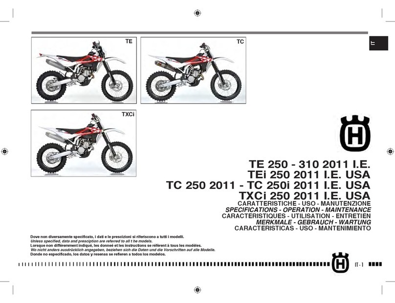
This publication is designed for use by HUSQVARNA Service Centres to assist authorised personnel in the maintenance
and repair of the models covered in this manual. The technical information provided in this manual is a critical complement
to operator training and operators should become thoroughly familiar with it.
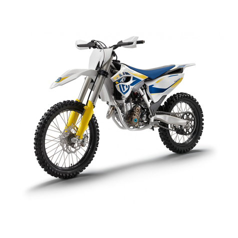
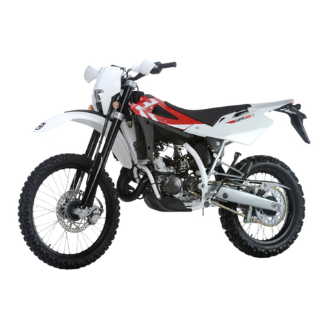
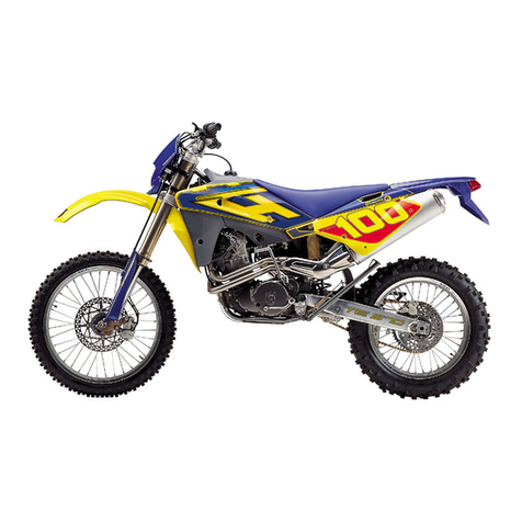
For ease of understanding, diagrams and photographs are provided next to the text.
Notes with special signicance are identied as follows throughout the manual:
Accident-prevention rules for operator and persons working nearby.
Damage to vehicle and/or its components may result from incompliance with relevant instructions.
Additional information concerning the operation covered in the text.
Useful tips
To prevent problems and ensure effective service work, observe the following HUSQVARNA recommendations:
– before repair, evaluate the customer's description of the problem and ask the appropriate questions to clearly identify
problem symptoms;
– diagnose the problem and identify the causes clearly. This manual provides basic background information that must
be supplemented with the operator's expertise and specic training available through HUSQVARNA held at regular
periods;
– plan ahead before starting work: gather any spare parts and tools to avoid unnecessary delays;
– avoid unnecessary disassembly work to get to the part that needs repairing.
Always read the relevant instructions and follow the disassembly sequence outlined in this manual.
Recommended shop practices
1 Always replace gaskets, sealing rings and split pins with new ones.
2 When loosening or tightening nuts or bolts, always begin with the bigger ones or from the centre. Tighten to the spe-
cied torque and follow a cross pattern.
3 Always mark any parts or positions that might be confused upon assembly.
4 Use genuine HUSQVARNA parts and the recommended lubricant brands.
5 Use special tools where specied.
6 Technical Bulletins might contain more up-to-date setting data and procedures than this manual. Be sure to read
them.
IMPORTANT: Where not specied, reassembled components must be tightened to the proper torque as indicated
in the tables provided in Chapter "x".
