Hussmann Smart Exchange User manual

SMART EXCHANGE
Installation & Operation Manual
P/N 3110238_B
March 2021
Spanish P/N 3110240
French P/N 3131231
Shipped With Data Sheets
Manual - I/O Smart Exchange
Lockers with Control Kiosk
Low, Medium & Ambient Temperature
IMPORTANT
Outdoor Locker Assembly Indoor Locker Assembly
See separate instructions (PN 3139727) for
Field Software Commissioning.

P/N 3110238_B U.S. & Canada 1-800-922-1919 • Mexico 01-800-890-2900 • www.hussmann.com
ii
BEFORE YOU BEGIN
Read the safety information completely and carefully.
The precautions and use of the procedures described herein are intended to use the locker assembly
correctly and safely. Please be sure to comply with the precautions described in this manual to protect
you and others from possible harm. The denitions below detail and clarify the magnitude and urgency
of potential harm, damage and problems arising from misuse of the locker assembly. Relative to their potential
danger, the denitions are divided into four parts as dened by ANSI Z535 Series.
REVISION HISTORY
REVISION B
1. Revised instructions for the outdoor canopy frame,
cameras and lighting assembly; Added denitions of
terminology and updated throughout the manual;
Added Appendix
REVISION A
1. ...........................Original issue.
ANSI Z535.5 DEFINITIONS
• DANGER – Indicate[s] a hazardous
situation which, if not avoided, will
result in death or serious injury.
• WARNING –Indicate[s] a hazardous
situation which, if not avoided,
could
result in death or serious injury.
• CAUTION –Indicate[s] a hazardous
situation which, if not avoided, could
result in minor or moderate injury.
• NOTICE – Not related to personal injury –
Indicates[s] situations, which if not avoided,
could result in damage to the locker assembly.
* * * * * * * * * * * * * * * * * * * * * * * * * *
DEFINITIONS OF TERMINOLOGY
The denitions below are a description of the
terminology used throughout this installation
and operation manual.
• Refrigerated module: refers to refrigerated
ambient, medium and low temperature
lockers with a refrigeration system
• Locker: refers to the small, metal compartment(s)
located in dry or refrigerated modules
• Locker assembly: refers to dry ambient,
refrigerated ambient, medium temperature
and/or low temperature modules assembled
together in a lineup
• Kiosk or control kiosk: refers to the
electronic component module

HUSSMANN CORPORATION • BRIDGETON, MO 63044-2483 U.S.A.
P/N 3110238_B iii
Smart Exchange Food Lockers
This manual was written in accordance
with originally perscribed components that
is subject to change. Hussmann reserves
the right to change all or parts of the locker
assembly for future stores such as, but not
limited to, controllers, refrigeration and
electrical specifications and requirements.
Personal Protection Equipment (PPE)
Only qualied personnel should install and
service the locker assembly and / or compo-
nents. Personal Protection Equipment (PPE)
is required whenever servicing any components
of the locker assembly. Wear safety glasses,
gloves, protective boots or shoes, long pants,
and a long-sleeve shirt when working with the
locker assembly. Observe all precautions on
tags, stickers, labels and literature attached to
the locker assembly.
Contractors shall strictly adhere to speci-
cations provided by the Engineer of Record
(EOR), as well as US Environmental Protection
Agency regulations, OSHA regulations, and
all other federal, state and local codes. This
work should only be done by qualied, licen-
sed contractors. There are numerous hazards,
not limited to, but including: burns due to
high temperatures, high pressures, toxic subs-
tances, electrical arcs and shocks, very heavy
weights with specic lift points and structural
constraints, food and product damage or conta-
mination, public safety, noise, and possible
environmental damage.
— LOCK OUT / TAG OUT —
To avoid serious injury or death from elec-
trical shock, always disconnect the electrical
power at the main disconnect when servicing
or replacing any electrical component. This in-
cludes, but is not limited to, such items as con-
trollers, electrical panels, condensers, lights,
fans, and heaters.
Proper Field Wiring and Grounding Required!
Failure to follow code could result in death
or serious injury. All eld wiring MUST be per-
formed by qualied personnel. Improperly
installed and grounded field wiring poses
FIRE, SHOCK and ELECTROCUTION
hazards. To avoid these hazards, you MUST
follow requirements for eld wiring installation
and grounding as described in NEC and your
local/state electrical codes.
Be sure to place the locker assembly on solid
ground and take measures to prevent it from
tipping over. If the ground is not solid or the
place is not appropriate, it may lead to damage
to the locker assembly and personnel injury.
The locker assembly shall not be installed in a
place where ammable or volatile materials are
stored. Otherwise, it may cause an explosion
or re. It shall not be installed in areas with
acid or corrosive gases. Otherwise, it will
cause leakage or electric shock due to reduced
insulation class arising from the corrosion of
electrical products.

P/N 3110238_B U.S. & Canada 1-800-922-1919 • Mexico 01-800-890-2900 • www.hussmann.com
iv
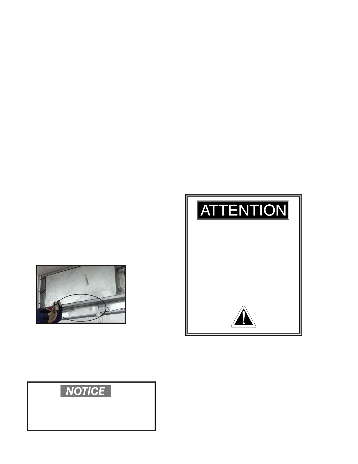
Please use a junction box with a ground wire to
prevent electric shock. If the power supply is not
grounded, contact an electrician, otherwise it may
cause electric shock.
Do not connect the grounding wire to the
grounding wire of gas pipe, water pipe, lightning
conductor and telephone; otherwise, it will lead to
electric shock.
Please strictly observe the rated voltage frequency
on the label of this product; otherwise it will cause
re or electric shock.
Do not store volatile or ammable materials in
or on top of this device; otherwise it may cause
explosion or re.
Do not insert metal objects such as nails or wires
into the vents or gaps in the device; otherwise,
it may result in electric shock or injury due to
actuation of the drive components.
Before performing any repair or maintenance,
be sure to disconnect the power at the main
disconnect, otherwise it may lead to electric shock
or personnel injury
Do not touch electrical parts (power plug, etc.) or
operate the switch with wet hands, otherwise it will
cause electric shock.
It is forbidden to pour water directly onto or inside
of the locker assembly or to place a container
containing liquid on the locker assembly. Liquid
spills will reduce the degree of insulation and cause
electric leakage or electric shock.
Please do not knot, tamper, crush or destroy the
power cord (if used or supplied).
Users are not allowed to disassemble, repair or
modify this product. Otherwise, it may result in re
or personal injury and void the warranty.
Before moving this product, disconnect the power
supply, and be sure not to damage the wiring, the
power cord, or wire whip. Otherwise it may cause
electric shock or re.
Dust accumulation or poor connection will cause
heating or re.
If the product is unused for a long time in an unsu-
pervised area, please ensure that children cannot
approach the product when doors are not closed
completely and locked (Otherwise, children may
climb and be trapped in the cabinet).
The product disassembles and scrap shall be con-
ducted by professionals. If it is placed without
management, it may trap children.
The power supply conforming to the specication
on the serial plate of this product may serves as a
separate dedicated power supply (equipped with
an isolator).
Do not preserve non-airtight acidic or alkaline
samples. It will corrode the box inner walls and
electrical components.
When powering off or restarting the device after
power is turned off, you need to check the product
conditions. Changes in the settings may damage
the saved items.
When the overheating alarm is caused by poor
heat dissipation of the product, please first
transfer the items in the cabinet to other suitable
containers for storage, and then inform the
professional maintenance service personnel.
When moving the product, be careful not to tip
the device over to prevent damage or personal
injury.
When this product has an emergency failure,
please do not repair without authorization, and
promptly notify the professional maintenance
technicians.
When the product is not used for a long time,
disconnect the power supply to prevent electric
shock, leakage or re caused by aging insulation.

HUSSMANN CORPORATION • BRIDGETON, MO 63044-2483 U.S.A.
P/N 3110238_B v
Smart Exchange Food Lockers
TABLE OF CONTENTS
SAFETY
Before you Begin (Denitions of Terminology) ii
PPE & Safety Statements iii
Purchase & Warranty Message vi
Environmental Concerns / Safety vi
INSTALLATION
Special Installation Requirements 1-1
UL Listing 1-2
Fed/State Regulation 1-2
Serial Plate Location 1-2
Product Temperature 1-2
QR Code 1-2
Refrigerated Module Naming Convention 1-3
Site Preparation 1-4
Shipping Damage 1-5
Shipping Skid 1-5
Unloading from Truck/Trailer 1-5
Unloading Indoor Refrigerated Modules 1-5
Refrigerated Module Leveling 1-6
MECHANICAL INSTALLATION
Fit & Secure Refrigerated Modules Together 1-7
Install Concrete Wedge Anchor 1-8
Installing Canopy Frame Assembly 1-9
Joining Canopy Modules Together 1-10
Install Refrigerated Module Splashguards 1-11
Installing Control Kiosk Splashguards 1-11
Install End Splashguard Close-o 1-12
Install Joint Trim 1-12
FIELD CONNECTIONS
Electrical 2-1
Filed Wiring 2-1
Main Disconnect Switch 2-1
Ethernet 2-1
Electrical Wiring Routes 2-2
LED Light Channel Installation 2-3
Installing Lighting 2-4
Security Camera Installation 2-5
Refrigeration Startup 2-7
Installing Top Panels and Water Tray(s) 2-8
Control Kiosk Field Connections 2-9
ELECTRONIC CONTROLLER
Electronic Controller 3-2
Internal Web Server 3-2
Data Logging 3-2
Factory Restore 3-2
Standalone Operation 3-2
Connecting to CoreLink (Wireless) 3-3
Direct Wired Connection 3-6
Connecting to CoreLink-(Wired) 3-7
Connecting to CoreLink-(Store Network) 3-9
Fixing Common Connection Issues 3-10
REFRIGERATION
Refrigeration 4-1
Condensing Unit Access 4-1
Sequence of Operation 4-2
Defrost 4-2
Low Ambient Heating Mode 4-2
Evaporator Fans 4-3
Condenser and Winter Holdback 4-3
Heaters 4-3
Additional Safeties 4-4
Compressor Safeties 4-4
Startup Check List 4-5
Starting Regerated Modules 4-6
12-Hours after Startup Checklist 4-6
Startup & Operation 4-6
Stocking 4-7
Maximum Locker Volumes 4-7
Waste Outlet and Water Seal 4-7
Installing FDA/NSF Required Thermometer 4-7
USING THE LOCKERS
Add/Remove Users 5-1
Placing Orders 5-1
Locker Reservation Process 5-3
MAINTENANCE
Back Panel Access 6-1
Care & Cleaning 6-1
Cleaning Stainless Steel Surfaces 6-2
Cleaning Coils 6-2
Cleaning Condensate Catch Pan 6-2
SERVICE
Locker Assembly Component Access (Outdoor) 7-1
Locker Assembly Component Access (Indoor) 7-3
Replacing Fan Motors and Blades 7-4
Replacing Heaters 7-4
Replacing Door Gaskets 7-5
APPENDIX - (CORELINK FACTORY SETPOINTS)
WARRANTY

P/N 3110238_B U.S. & Canada 1-800-922-1919 • Mexico 01-800-890-2900 • www.hussmann.com
vi
Thank you for purchasing the Smart Exchange Food Locker!
Before you begin, please read the installation instructions completely and carefully.
Hussmann Corporation shall not provide any safety guarantee for the use, purpose and method beyond
this instruction manual. The content within this instruction manual is expected to be complete and correct.
If you nd any errors or omissions, please contact our business department or distributor.
No individual or organization may reproduce any part of this instruction manual in any form without
the prior written consent of Hussmann. This product is equipped with components including a variety of
security and alarm functions, a remote alarm system and automatic temperature recording devices.
The lockers are manufactured to protect products in the cabinet. Please contact your local sales representative
or visit www.hussmann.com for more information. Hussmann is responsible for product failure from
meeting the requirements of xed conditions, and shall not be responsible for sample and reagent losses
restored in product.
For questions about camera kit installation instructions contact the Hussmann Support Center (800)-592-2060.
For camera operation and specications, see instruction manual from the camera manufacturer.
ENVIRONMENTAL CONCERNS
Hussmann recommends responsible handling of
refrigerants that contain Hydrogen, Fluorine and
Carbon (HFCs). Only certied technicians may
handle these refrigerants. All technicians must be
aware and follow the requirements set forth by the
Federal Clean Air Act (Section 608) for any service
procedure being performed that involves refrigerant.
Additionally, some states have other requirements
that must be adhered to for responsible manage-
ment of refrigerants. This warning does not mean that Hussmann
products will cause cancer or reproductive harm, or
is in violation of any product-safety standards or
requirements. As clarified by the California State
government, Proposition 65 can be considered
more of a ‘right to know’ law than a pure product
safety law. When used as designed, Hussmann
believes that our products are not harmful. We
provide the Proposition 65 warning to stay in
compliance with California State law. It is your
responsibility to provide accurate Proposition 65
warning labels to your customers when necessary.
For more information on Proposition 65, please
visit the California State government website.
August 31, 2018
SERVICING
Component parts shall be replaced with like
components. Service is to be performed by
factory authroized service personnel, so as to
minimize the risk of possible ignition due to
incorrect parts or improper service. Contact
your Hussmann representative to arrange
servicing.

HUSSMANN CORPORATION • BRIDGETON, MO 63044-2483 U.S.A.
P/N 3110238_B 1-1
Smart Exchange Food Lockers
SPECIAL INSTALLATION REQUIREMENTS
Consult with the appropriate structural design professional for special installation requirements in your area for
conditions not covered by this design. See below.
•
Sites where an active fault could cause the ground to rupture at the surface
•
Sites dened as Site Class F in ASCE 7-16, Chapter 20 (poor or liqueable soil). These sites
require a site response analysis to be performed by a Geotechnical Engineer in order to determine the Sds
value, per ASCE 7-16 Section 11.4.7
•
Sites where the refrigerated modules are installed above ground level
•
Mountaintop sites in Hawaii where the effective design wind speed (per ASCE 7-16 Figure 26.5-2B) exceeds
180 mph
•
Sites in Florida or Southeast Louisiana where the locker assembly has an unobstructed view of an
ocean or large lake and / or wind speeds right on the coast/beach can exceed the rated capacity of the locker
assembly’s anchorage
•
Sites where both Kzt > 1.5 and V > 145 mph per ASCE 7-16, Section 26.8. This would be sites where the
locker assembly will be sitting on the top of, or face of, any terrain feature (hill, ridge, escarpment, etc.)
with a slope greater than 1:10 in any of the following regions. For reference, 1:10 slope is about the maxi-
mum possible for pushing wheelchairs or riding bicycles.
•
Florida south of Orlando
•
Within 50 miles of the Gulf of Mexico
•
North Carolina or South Carolina within 10 miles of the ocean
•
Installations in hurricane zones
INSTALLATION

P/N 3110238_B U.S. & Canada 1-800-922-1919 • Mexico 01-800-890-2900 • www.hussmann.com
1-2
UL LISTING
The refrigerated modules are safety listed with
UL-471 and sanitation listed to NSF-7. The con-
trol kiosk is safety certied to UL-60950-1 &
UL-60950-22. Proper installation is required to
maintain this listing.
FEDERAL / STATE REGULATION
Locker assemblies at the time manufactured,
meet all federal and state/ provincial regulations.
Proper installation is required to ensure these
standards are maintained. A key must be used
to remove the louver panel or kiosk panel See
the serial plate.
SERIAL PLATE LOCATION
Serial plates are located for each module behind
the top panel just above the locker cabinets.
The serial plate contains information about the
specic model and its operating parameters. A
key is needed to remove the front louvre panel to
access the serial plate.
LOCKER ASSEMBLY LOCATION
Locker assemblies are designed for temporarily
holding products in both indoor and outdoor
environments.
While locker assemblies are designed to work
in the harshest conditions, below is a list of
things to consider when choosing outdoor
placement location:
•
Exposure to sunlight
•
Exposure to strong wind currents
•
Exposure to rapid temperature changes
•
Exposure to areas inclined to ooding
PRODUCT TEMPERATURE
Product should always be maintained at proper
temperature. This means that from the time the
product is received, through receiving, transportation
and storage, the temperature of the product
must be controlled to maximize product life.
Locker assembly must operate for
24 hours before loading product.
Regularly check temperatures.
Do not break the cold chain.
Keep products in cooler or freezer
before loading into the locker assembly.
Medium temperature refrigerated modules
are designed for ONLY loading pre-chilled
products. Low temperature refrigerated
modules are designed for ONLY loading
frozen products.
A 4-inch unobstructed space between
the rear of the locker assembly and the
nearest structure must be maintained
for proper air circulation.
Figure 1-1 Serial Plate Location
QR CODE
Refrigerated modules have a QR code near the
serial plate, which is located above locker cab-
inets of each module. Once you scan the QR
code, all of the information about that the locker
assembly will be at your ngertips. Links to installa-
tion manuals and data sheets, as well as a link for
ordering replacement parts from
Hussmann’s Performance Parts Website.

HUSSMANN CORPORATION • BRIDGETON, MO 63044-2483 U.S.A.
P/N 3110238_B 1-3
Smart Exchange Food Lockers
Refrigerated
Module
Refrigerated
Module
Refrigerated
Module
Control
Kiosk
Module
SMART EXCHANGE MODEL KEY
Smart Locker
Type
I = Indoor
O = Outdoor
Number Of Doors
Refrigerated Module
A = Ambient Temperature (Discharge Air Temp =65° F)
M = Medium Temperature (Discharge Air Temp =33° F)
L= Low Temperature (Discharge Air Temp =-4° F)
C = Control Kiosk (Display Screen)
S L O L 8
REFRIGERATED MODULE
NAMING CONVENTION
Smart Exchange locker assembly follow the
naming convention listed below.
Model numbers are listed on the serial plate
for each module.

P/N 3110238_B U.S. & Canada 1-800-922-1919 • Mexico 01-800-890-2900 • www.hussmann.com
1-4
SITE PREPARATION
The locker assembly has a modular design
based on customer requirements. Suitable site
requirements must be met for the refrigerated
modules to perform properly. A stable and rm
base for the locker assembly to be secured to is
the most important requirement when selecting
location. Hussmann recommends a concrete
slab of at least 6"thick and extending beyond
the outer edges of the refrigerated module no
less than 12"reinforced with ½"steel rebar
according to local building codes.
The illustration below is an example of the plan
view used to locate and place the anchor bolts
in their proper locations.
Using blueprints, measure off and markbolt
hole locations of the locker assembly footprint.
Walk the area, noticing any dips or mounds,
use a string level and a transit. If no new con-
rete has been laid, holes in the concrete can be
drilled and 5/8"anchors can be used to secure
the locker assembly in place.
Always comply with your local government’s
building codes.
Modules may be congured differently. Consult
Hussmann for specic requirements.
Anchor Bolt Locations shown with =
Figure 1-2 Refrigerated Module
Plan View (Top View) Figure 1-3 Control Kiosk
Plan View (Top View)
SHEET 4 OF 6
72.57
49.14
SLOL8 / SLOM8 / SLOA8
31.37
5.538.15
5.5
1.01
FRONT
BOTTOM
PANEL
36.49 31.37
2.51 18.98 2.51
24.00
72.57
O
. 7 54 X
1.01
36.54
FRONT
BOTTOM
PANEL

HUSSMANN CORPORATION • BRIDGETON, MO 63044-2483 U.S.A.
P/N 3110238_B 1-5
Smart Exchange Food Lockers
SHIPPING DAMAGE
Control kiosk and refrigerated modules should
be thoroughly examined for shipping damage
before and during unloading.
Refrigerated modules have been carefully inspected
at our factory. Any claim for loss or damage
must be made to the carrier. The carrier will
provide any necessary inspection reports and/
or claim forms.
Apparent Loss or Damage
If there is an obvious loss or damage, it must be
noted on the freight bill or express receipt and
signed by the carrier’s agent; otherwise, carrier
may refuse claim.
Concealed Loss or Damage
When loss or damage is not apparent until after
refrigerated modules are uncrated, retain all packing
materials and submit a written request to the
carrier for inspection, within 15 days.
SHIPPING SKID
Each refrigerated module and control kiosk
(module) is shipped on a skid to protect the
base and to make positioning easier.
Do not remove the shipping skid until the
refrigerated modules are near the nal location.
The shipping skid is fastened to the refriger-
ated module’s base with bolts. Remove the
bolts in order to remove the skid. Once the
skid is removed, modules must be lifted —
NOT PUSHED— to reposition.
UNLOADING FROM TRUCK / TRAILER
Unless specically arranged otherwise, it is
the customer’s responsibility to arrange the
off-loading, unpacking, and moving of the
locker assembly to the nal site location.
Improper handling may cause damage when
unloading. A forklift is recommended. Pallet
jacks can also be helpful in moving a refriger-
ated module to its permanent location.
UNLOADING INDOOR REFRIGERATED
MODULES
Indoor refrigerated modules can be tilted over
on the compressor side in order to move the
refrigerated modules into the store if shipped
with a tilt-rider kit. The refrigeration system
can not be started until after 24 hours after it has
been tilted over on its’ side. Damage to the
refrigeration system may result if the refrigerated
modules are started up sooner.
Use extreme caution when lifting or
moving refrigerated modules. Tall objects
may be prone to tip over. Always remain
at a safe distance to avoid severe injury or
death.
Do not start refrigeration until 24 hours
after condensing units were righted after
being tilted or tipped over.

P/N 3110238_B U.S. & Canada 1-800-922-1919 • Mexico 01-800-890-2900 • www.hussmann.com
1-6
When moving the refrigerated modules, keep
distance between it and the ground to a min-
imum. It may also be helpful to secure the
refrigerated module to the forks via rope or
straps.
4.The refrigerated module may be moved at
its end to help position to the nal location.
Start removing the shipping skid at bolt hole
locations around the locker assembly.
3.Once the forks are completely underneath,
the refrigerated module can be slowly
lifted. Make sure the module remains sta-
ble througout the lifting process.
REFRIGERATED MODULE LEVELING
Line the refrigerated moduled and control
kiosk up in the order needed (only place in level
locations that are solidly supported).
Using a 4 ft. level, ensure level from front to
back and back to front. Level modules by all four
corners. Place shims underneath the base as
needed in order to adjust and make the refrig-
erated module or control kiosk level.
1. Unstrap and remove packaging from the
separately shipped items for the canopy.
2.Lift each refrigerated and control kiosk module
from the back side. Position the forks under
base at the center until forklift carriage is ush
against the module’s base.
It may be necessary to cut or partially remove
the shipping skid in order to access the base of
each module.
Figure 1-4 Lifting Location Proper Field Wiring and Grounding Required!
Failure to follow code could result in death or se-
rious injury. All field wiring MUST be performed
by qualified personnel. Improperly installed and
grounded field wiring poses FIRE and ELEC-
TROCUTION hazards. To avoid these hazards,
you MUST follow requirements for field wiring
installation and grounding as described in NEC
and your local/state electrical codes.

HUSSMANN CORPORATION • BRIDGETON, MO 63044-2483 U.S.A.
P/N 3110238_B 1-7
Smart Exchange Food Lockers
MECHANICAL INSTALLATION
Figure 1-5a Bolt, Washer, and Nut
for Rear Base Bracket
FIT & SECURE REFRIGERATED
MODULES TOGETHER
Refrigerated modules or control kiosks
are bolted together at rear-rail supports as
shown below.
Use bolt, washer and nut to fasten and secure
together at the rear of refrigerated modules.
WASHER-FLAT 0.375
BOLT-CARRIAGE 0.375-16 X 11 ROUND HD
NUT-HEX 3/8-16 STEEL ZINC PLT
LOCKWASHER-3/8 SPLIT STEEL ZINC PLATED
Figure 1-5b Secure Rear-rail Supports together

P/N 3110238_B U.S. & Canada 1-800-922-1919 • Mexico 01-800-890-2900 • www.hussmann.com
1-8
INSTALL CONCRETE WEDGE ANCHORS
Front Concrete Anchors:
1. Drill 5/8"diameter holes in the concrete 5
inches deep. Holes may be drilled at an angle.
Rear Concrete Anchors:
2. Drive the 5/8"x 4 ½"anchor into the
concrete and tighten the nut.
Figure 1-6a Concrete Wedge Anchor
Figure 1-6b Anchors secured in concrete
(refrigeration module front shown)
FRONT VIEW
REAR VIEW
Figure 1-6c Anchors secured in concrete
(refrigeration module rear shown)

HUSSMANN CORPORATION • BRIDGETON, MO 63044-2483 U.S.A.
P/N 3110238_B 1-9
Smart Exchange Food Lockers
INSTALLING CANOPY FRAME ASSEMBLY
(FOR OUTDOOR LOCKER ASSEMBLIES)
1. Assemble the canopy frame. Control kiosk canopy installation is similar. See Figure 1-7a
below. The frame will be installed on the refrigerated module or control kiosk in the next
step.
Figure 1-7a Top View of Canopy Frame Assembly
(Kiosk Canopy Frame Assembly is similar.)
2. Fasten Canopy Frame Assembly to modules(s) as shown in Figure 1-7b.
Figure 1-7b Top View of Canopy Frames attached to Refrigerated Module and Contol Kiosk
BRACE-CROSS
CANOPY LOCKER
BRACE-CROSS
2 INCH CANOPY
LOCKER
SUPPORT-LH/RH
OUTDOOR CANOPY
LOCKER
QTY - 2
SCREW
1/4-20 X 3/4
QTY - 8
CANOPY FRAME ASSEMBLY
LOCKER (KIOSK SIMILAR)
MODULE-CANOPY
OUTDOOR FRAME KIOSK
MODULE-CANOPY
OUTDOOR FRAME LOCKER
SCREW-10-16 X 0.5"
TEK HEX QTY - 12

P/N 3110238_B U.S. & Canada 1-800-922-1919 • Mexico 01-800-890-2900 • www.hussmann.com
1-10
Figure 1-8b Attach Outdoor Canopy Frames - Refrigerated Module to Kiosk
JOINING CANOPY MODULES
TOGETHER
(refrigerated modules or control kiosk)
1. Fasten canopy supports together at the
joining locations shown in Figure 1-8b.
Figure 1-8a Attach Canopy Frames
Do not install top panels on
outdoor locker assemblies until
after the refrigeration and
electrical is ready and operating.
SCREW-CAP 3/8-16 X 1
1/4 HEX HD QTY- 3
WASHER-FLAT
0.375 QTY - 3
WASHER-FLAT
0.375 QTY - 3
NUT-HEX .0375-16
UNC QTY - 3
LOCKWASHER-3/8
SPLIT STEEL QTY - 3

HUSSMANN CORPORATION • BRIDGETON, MO 63044-2483 U.S.A.
P/N 3110238_B 1-11
Smart Exchange Food Lockers
INSTALL REFRIGERATED MODULE
SPLASHGUARDS
1. Fasten with #8 sheet metal screws as shown in Figure 1-9 / 1-10.
SCREW-8 X 9/16 TEK WFR HD
QTY - 4
SPLASHGUARD
FRONT LOWER TOP
SPLASHGUARD
FRONT LOWER BOTTOM
Splashguard
Front Lower Bottom
Splashguard
Front Lower Top
Screw #8 x 9/16
Quantity 4
Figure 1-9 Install
Regerated Module
Splashguards
INSTALLING CONTROL KIOSK
SPLASHGUARDS
REVISION HISTORY
REV ECN DATE REVISION DESCRIPTION REV BY CHKD BY APPR BY
AECN-
SPLASHGUARD
FRONT LOWER TOP
SPLASHGUARD
FRONT LOWER BOTTOM
SCREW-8 X 9/16 TEK WFR HD
QTY - 4
Screw #8 x 9/16
Quantity 4
Splashguard
Front Lower Top
Splashguard
Front Lower Bottom
Figure 1-10 Install Control
Kiosk Splashguards

P/N 3110238_B U.S. & Canada 1-800-922-1919 • Mexico 01-800-890-2900 • www.hussmann.com
1-12
COVER-TOP FRONT TRIM LOCKER
SCREW-8 X 9/16 TEK WFR HD
QTY - 4
(FASTENING HOLES WILL NEED TO BE ADDED)
SCREW-8 X 9/16 TEK WFR HD
QTY - 4
(FASTENING HOLES WILL NEED TO BE ADDED)
COVER-TOP FRONT TRIM LOCKER
(MAY NEED TO BE TRIMMED)
INSTALL JOINT TRIM
1. Add the joint trim between the refrigerated
modules. Front joint trim can be shortened
by cutting as needed.
COVER-TOP FRONT TRIM LOCKER
SCREW-8 X 9/16 TEK WFR HD
QTY - 4
(FASTENING HOLES WILL NEED TO BE ADDED)
SCREW-8 X 9/16 TEK WFR HD
QTY - 4
(FASTENING HOLES WILL NEED TO BE ADDED)
COVER-TOP FRONT TRIM LOCKER
(MAY NEED TO BE TRIMMED)
Front Joint Trim
Screw #8 x 9/16
Quantity 4 Screw #8 x 9/16
Quantity 4
Front Joint Trim
INSTALL END SPLASHGUARD CLOSE-OFF
1. Install side splashguard with four screws as
shown in Figure 1-11.
SPLASHGUARD-RH END CLOSEOFF
SCREW-8 X 9/16 TEK WFR HD
QTY 5
THIS SURFACE TUCKED
BEHIND SIDE FLANGES
Splashguard
End Close-Off
Screw #8 x 9/16
Quantity 5
This surface tucked
behind side anges
Figure 1-11 Install End
Splashguard Close-off
Figure 1-12 Install Joint
Trim between Modules

HUSSMANN CORPORATION • BRIDGETON, MO 63044-2483 U.S.A.
P/N 3110238_B 2-1
Smart Exchange Food Lockers
MAIN DISCONNECT SWITCH
Each refrigerated module is equipped with a
dedicated main disconnect switch/breaker. The
switch will interrupt power to the entire refrigerated
module. The switch is located on the right side
of the refrigerated module control panels (when
facing them), and on the inside electrical panel
behind the display screen of the kiosk. The
image below shows the disconnect switches.
Electrical Connection
(rear of refrigerated module)
ETHERNET
Connectivity to the Internet is provided by the
customer building or using a 4G cellular card.
Please see Steps in this Section to connect
Ethernet to control kiosk via the Sophos device.
For software and software component remote
troubleshooting, call 1-866-386-9398.
CONDENSING UNIT WITH ELECTRICAL PANEL LOWERED FOR MAINTENANCE
EVAPORATOR FAN
TXV
DISCONNECT
SWITCHES
COMPRESSOR
CONDENSER COIL &
FAN ASSY
LOW PRESSURE SWITCH
HIGH PRESSURE SWITCH
LIQUID RECEIVER
HEAD PRESSURE
VALVE
ACCUMULATOR
COMPRESSOR CRANKCASE HEATER
THERMOSTAT (LOW TEMP CASE ONLY)
HEATER LIMIT THERMOSTAT
EVAPORATOR COIL
Disconnect Switches
FIELD CONNECTIONS
Proper Field Wiring and Grounding Required!
Failure to follow code could result in death or serious
injury. All field wiring MUST be performed by qualified
personnel. Improperly installed and grounded field
wiring poses FIRE and ELECTROCUTION hazards.
To avoid these hazards, you MUST follow require-
ments for field wiring installation and grounding as
described in NEC and your local/state electrical codes.
SHEET 6 OF 6
84.07
1.82
ELECTRICAL
The locker assembly is electronically controlled
by the CoreLink Controller. Refer to the serial
plate or data sheets for electrical information.
Field wiring is done at the junction box located at
the rear of each refrigerated module.
FIELD WIRING
Field wiring must be sized for component amperes
stamped on the serial plate. Actual ampere
draw may be less than specied.
It is the responsibility of the installing contractor(s)
to make connections and ensure local codes are
followed. See wiring diagram and circuit re-
quirements for each refrigerated module before
making any electrical connections.
ALWAYS CHECK THE SERIAL PLATE FOR
COMPONENT AMPERES.
Electrical
Junction
1.8”
84”

P/N 3110238_B U.S. & Canada 1-800-922-1919 • Mexico 01-800-890-2900 • www.hussmann.com
2-2
A
DETAIL A
B
DETAIL B
TIE-CABLE
ADHESIVE
BACKED
QTY - 12
BUSHING- .875 BETWEEN
CANOPY RAILS
(SURVEILLANCE KIT ONLY)
CABLE WITH BLACK
WHITE & GREEN
LEADS FOR LED
LIGHTNING
CABLE WITH BLACK WHITE &
GREEN LEADS FOR LED LAMP TO
BE RUN ON RIGHT SIDE OF
KIOSK CANOPY RAIL
INSTALL ADHESIVE
BACKED CABLE TIES
CABLE-RJ45 ETHERNET 25FT
(SURVEILLANCE KIT ONLY) TO
BE RUN ON LEFT SIDE OF
KIOSK CANOPY RAIL
INSTALL ADHESIVE
BACKED CABLE TIES
CABLE-RJ45
ETHERNET 25FT
ELECTRICAL WIRING ROUTES
OUTDOOR REFRIGERATED MODULE &
KIOSK
1. Route leads for LED lighting and security
cameras.
Field Module Wiring (Canopy)
Other manuals for Smart Exchange
1
Table of contents
Other Hussmann Indoor Furnishing manuals
Popular Indoor Furnishing manuals by other brands

Walker Edison
Walker Edison BR25LINNS Assembly instructions

Songmics
Songmics VASAGLE LLS35 Assembly instructions

Office Star Products
Office Star Products WORK SMART DCY69006 operating instructions

KI
KI U Series Assembly instructions

Manual Thinking
Manual Thinking MT-VP S160 Assembly instructions

BluDot
BluDot Chicago 8 Box Assembly notes