INDEX
1Description ...............................................................................................................................................5
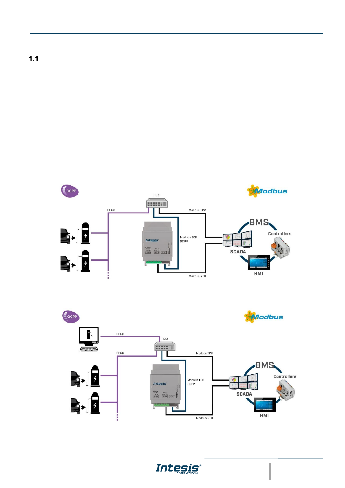
Introduction.......................................................................................................................................5
Functionality .....................................................................................................................................6
Gateway’s capacity ..........................................................................................................................6
2Modbus interface......................................................................................................................................7
Description........................................................................................................................................7
Functions supported.........................................................................................................................7
Modbus TCP.....................................................................................................................................7
Modbus RTU ....................................................................................................................................7
Address Map ....................................................................................................................................7
Points definition................................................................................................................................8
3Connections .............................................................................................................................................9
Powering the device.......................................................................................................................10
Connection to Modbus ...................................................................................................................10
3.2.1 Modbus TCP...........................................................................................................................10
3.2.2 Modbus RTU...........................................................................................................................10
Connection to the configuration tool...............................................................................................10
4Set-up process and troubleshooting ......................................................................................................11
Pre-requisites .................................................................................................................................11
Intesis MAPS. Configuration & monitoring tool for Intesis Modbus series.....................................11
4.2.1 Introduction.............................................................................................................................11
4.2.2 Connection..............................................................................................................................11
4.2.3 Configuration tab ....................................................................................................................12
4.2.4 Signals....................................................................................................................................14
4.2.5 Sending the configuration to Intesis .......................................................................................14
4.2.6 Diagnostic...............................................................................................................................15
Set-up procedure............................................................................................................................16
5Electrical & Mechanical Features...........................................................................................................17
6Dimensions ............................................................................................................................................18