Hybrid+ Hybrid Home 4,8 User manual

Hybrid Home 4,8 / 8,2
!
Hybrid Home
Instruction Manual
WWW.HYBRID.ENERGY

Welcome to Home!
You have now the ability to store your own generated green energy or finally have a
great back-up system that actually works in case of grid failure. We are very happy and
proud that you have chosen the world’s most advanced power storage solution.
Welcome to the Hybrid family!
In order to gain maximum fun and quality from your Hybrid Home system, please read
this instruction manual with great care; it will explain all functions and possibilities. If
you have any questions or remarks, feel free to let us know, since we care about what
you think and are constantly improving to make your experience more enjoyable. On our
website www.hybrid.energy you can find our FAQ list for general questions and any
additional information, should you require it.
For A Bright Future!
Team Hybrid.
About this manual
This manual contains information for all users of Hybrid Home battery storage systems.
Read it carefully to ensure the Hybrid Home energy storage systems operate correctly.
Installation and maintenance activities must be performed by a qualified and certified
electrician. The instruction manual should be kept in close proximity to the Hybrid Home
system and must be permanently available to all individuals involved in working on the
energy storage system for logging data purposes and quick access to the correct
information.
!
Legal Notice!
Translation of the original instruction manual Hybrid Home. All information contained in any and all Hybrid
documentation on or off line is copy righted to and remains in the ownership of Hybrid Pty Ltd. With all Hybrid
products when purchased, the purchaser becomes automatically bound to a strict non-disclosure agreement in
order to protect the user and Hybrid’s proprietary information and technology. The user agrees to give Hybrid full
access to backend systems to run updates of firmware and receive system alerts in the event that such alerts
may happen or to do trouble shooting in the event of a failure.
Hybrid Europe B.V.!
Rijnzathe 4!
3453 PV Utrecht!
The Netherlands
Tel.: +31 (0)88 - 0186 220!
Technical support:!
1

Disclaimer
Hybrid Europe BV accepts no liability whatsoever for personal injury, property damage,
damage sustained by the product, or consequential damage that occurs or has
occurred on the product due to failure to comply with these instructions, improper use
of the product, or by repairs, opening of the storage cabinet and any other actions
carried out by unqualified persons/electricians. This disclaimer also applies for the use
of non-approved spare parts and failure to comply with the specified maintenance
intervals, overloading the system or abusing it in any way or means.
The product must not be rebuilt or technically modified without authorisation.
© Hybrid Europe BV - 2016
Latest version: 05/2016!
2

Table Of Contents
1. Introduction to Hybrid Home 4......................................................
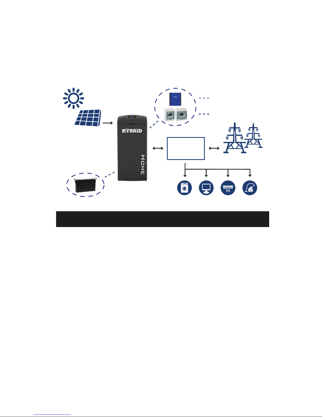
2. Hybrid Home Overview 5.................................................................
2-1. Welcome Home! 5.........................................................................................................
2-2. Hybrid Transport box 5..............................................................................................
2-3. Packing List 5................................................................................................................
2-4. Panel Overview Hybrid inverter 6...........................................................................
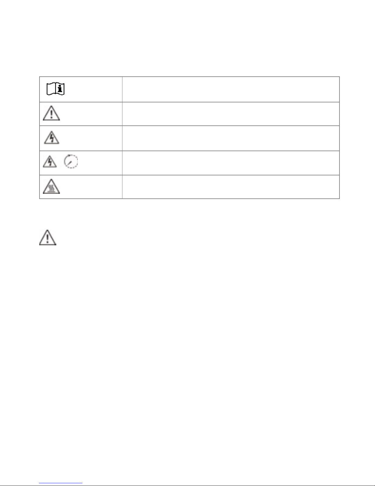
3. Safety 7...............................................................................................
4-1. Selecting Location 10..................................................................................................
4-2. Mounting Unit 10.........................................................................................................
4-3. Hybrid Installation 11...................................................................................................
4-3.1. Battery Installation (Lead Crystal) 11.................................................................
4-3.2. Battery assembly in Hybrid 12...........................................................................
5. Grid / Utility Connection 13..............................................................
5-1. Preparation 13................................................................................................................
5-2. Connecting to the AC Utility 13...............................................................................
5-3. Connecting AC Utility to Hybrid Home 14...........................................................
6. PV Module (DC) Connection 15......................................................
7. Load (AC Output) Connection 17...................................................
8. Communication 18............................................................................
9. Commissioning 19............................................................................
10.Remote LCD Operation 20..............................................................
10-1. Interface 20...................................................................................................................
10-2. LCD Information Defined 20..................................................................................
10-3. Button Definition 22..................................................................................................
10-4. Query Menu Operation 22......................................................................................
10-5. Operation Mode & Display 26................................................................................
11. Charging Management 29..............................................................
12. Applications with Energy Meter 30.............................................
13. Maintenance & Cleaning 31............................................................
14. Instructions for Disassembly and Disposal 32.........................
14. Trouble Shooting 33........................................................................
14-1. Warning List 33............................................................................................................
14-2. Fault Reference Codes 33......................................................................................
15. Specifications 39..............................................................................
3

1. Introduction to Hybrid Home
Hybrid Home is a smart all-in-one energy storage and distribution system to provide
you with energy whenever you want to use it. Hybrid is compatible with most renewable
energy sources, utility power (the grid) and even diesel/natural gas generators/
turbines to charge and maintain your storage battery packs.
Figure 1 Basic Hybrid Home System Overview
Depending on different power situations, the internal Hybrid inverter is designed to
utilize power from all available sources, PV solar modules (solar panels), batteries and
the utility grid. When MPPT controlled input voltage of PV modules are within
acceptable range (see specification for the details), the inverter is able to power the
loads (house), to feed/sell to the grid (utility) and charge batteries simultaneously.
Note: This inverter is only compatible with single crystalline (Mono) and poly crystalline
photo voltaic panels.
Do not connect any PV array types other than these two types to the inverter.
See Figure 1 for a simple diagram of a typical solar installation utilizing the hybrid
inverter.
Note: When the PV input voltage is lower than 250V for the 3KW and 3KW plus
inverters, the input PV power will de-rate and efficiencies will be reduced."
4
Figure 1 Basic hybrid PV System Overview
PV module
Utility
LoadBattery
Hybrid
House
distribution
box
Hybrid distribution box
Inverter

2. Hybrid Home Overview
2-1. Welcome Home!
Congratulations! You have just received your own Hybrid Home energy storage system.
Before you can start benefiting of your own generated power, just a few, but important
items need to be checked. Please carefully read this Hybrid manual. If you have any
questions, feel free to contact your authorized installer or Hybrid distributor in your area
(contact details can be found on www.hybrid.energy).
2-2. Hybrid Transport box
Since we love our planet, we have chosen to send your Hybrid Home in an
environmentally friendly, cardboard shipping box. This box has been made of recycled
materials and printed with non petrol chemical inks. You can dispose of this box
anywhere, but why not give it a third life by handing it in at paper collection site for
recycling or turn it in to mulch for your garden?
2-3. Packing List
Before installation, please inspect the Hybrid Home unit. Be sure that nothing inside the
package is damaged. You should have received the following items inside of package:
5

2-4. Panel Overview Hybrid inverter
The top of Hybrid inverter has the following connections, they should be pre wired on
arrival:
"
1) PV connection
2) AC Grid connection
3) Battery connection
4) AC output connection (Load
connection)"
5) RS-232 communication port
6) USB communication port
7) Intelligent slot / Wifi card module
8) Grounding Earth point"
6

3. Safety
3-1. Important Safety Warning
Before using the Hybrid Home system, please read all instructions and cautionary
markings on the unit and this manual. Store the manual where it can be accessed
easily for data logging and troubleshooting purposes.
This manual is to be used by all users and installers of Hybrid Home systems. However,
the tasks described in this manual need to be performed by qualified personnel only.
Qualified personnel is considered to be technically skilled and certified electricians.
Hybrid takes no responsibility if injury occurs to unqualified persons attempting to
install the equipment, all product related warrantees will also be void in such an event.
3-2. General Precaution
WARNING! Before installing and using this Hybrid Home system, read all instructions
and cautionary markings on the Hybrid inverter and all appropriate sections of this
guide.
WARNING! Normally grounded conductors may be ungrounded and energised when a
ground fault is indicated.
WARNING! The Hybrid inverter, batteries and frame are heavy. Take notice when lifting
it. It should be lifted by at least two persons.
CAUTION! Authorised service personnel should reduce the risk of electrical shock by
disconnecting AC and DC power from the inverter before attempting any maintenance
or cleaning or working on any circuits connected to the inverter. Turning off controls will
not reduce this risk. Internal capacitors can remain charged for 5 minutes after
disconnecting all sources of power.
7
Conventions used:
WARNING! Warnings identify conditions or practices that could result in personal
injury
CAUTION! Caution identify conditions or practices that could result in damaged to

CAUTION! Do not (dis-)assemble the Hybrid system yourself. It contains no user-
serviceable parts. Attempt to service the system yourself may cause a risk of electrical
shock or fire and will void the manufacturers warranty.
CAUTION! To avoid a risk of fire and electric shock, make sure that existing wiring is in
good condition and that the wire is not undersized. Do not operate the inverter with
damaged or substandard wiring.
CAUTION! Under high temperature environment, the cover of the Hybrid inverter could
be hot enough to cause skin burns if accidentally touched. Ensure that this inverter is
away from normal traffic areas.
CAUTION! Use only recommended accessories from installer and original
manufacturers parts. non approved tools and parts may cause a risk of fire, electric
shock, or injury to persons.
CAUTION! To reduce risk of fire hazard, do not cover or obstruct the cooling fan of the
inverter or the cooling fan on top of the Hybrid Home system.
CAUTION! Do not operate the Hybrid Home system if it has received a sharp blow, been
dropped, or otherwise damaged in any way. If the Hybrid Home is damaged, contact
your official installer for assistance.
CAUTION! The general life time of Hybrid under normal conditions (see conditions
under Chapter 4) is expected to be 7 to 10 years. Life time is strongly determined by the
number of (dis-)charge cycles in relationship to the depth of discharge of the batteries
(DOD). Shallow discharge means increasing life time. This relationship can be read
back on the Lead Crystal battery website (www.leadcrystalbatteries.com), under
“datasheets”.
8

Symbols used in Equipment Markings
3-3. General Information on Safety
WARNING!
Potential mortal danger through failure to observe the safety instructions! !
Improper use can cause fatal injury. Therefore: Make sure that all safety devices are in
working order before use!
The information contained in this manual is to be observed by all individuals during
operation, installation and maintenance. These instructions are unable to describe
every conceivable situation. Therefore, the applicable standards and the relevant
regulations for occupational health and safety shall govern.
Moreover, installation and maintenance work involves residual risks under the following
circumstances: !
- Installation and maintenance work is not performed correctly. !
- Installation and maintenance work is performed by personnel who have not been
trained and not been instructed. !
- The safety instructions given in these instructions are not observed. !
!
All persons assigned to work on the system must have read and understood these
instructions, in particular the chapter on Safety. !
!
All safety instructions must be strictly obeyed, compliance therewith ensures your
safety. The device must not be modified."
Refer to the operating instructions
Caution, risk of danger
Caution, risk of electric shock
Caution, risk of electric shock, energy storage timed
discharge
Caution, hot surface
!
!
!
!
!
9

4 Installation Hybrid Home
4-1. Selecting Location
Consider the following points before selecting where to install:
●Do not position the Hybrid Home on flammable construction materials
●Position on a solid surface with a load baring capacity of +500 kg per m2
●The Hybrid inverter emits sound during operation which may be perceived as a
nuisance in a living area
●For proper air circulation to dissipate heat, allow a clearance of approx. 20 cm to
the sides and approx. 50 cm above the unit
●Dust on or around the unit may impair the performance or cause failure
●The ambient temperature should be between -10°C and +40°C and relative
humidity should be between 5% and 85% to ensure optimal operation
●The recommended installation orientation position is to be adhered to at all times
●For proper operation of the Hybrid Home system, please use only approved and
appropriate cables for grid, load and PV connections
●Install the Hybrid Home in a protected area that is dry, free of excessive dust and
has adequate air flow
●Do NOT operate it where the temperature and humidity is beyond the specific
limits
●Installation position shall not prevent access to the means of disconnection
●The Hybrid Home is designed IP20 for indoor applications only
●Regularly clean the fan filter on top and bottom of the Hybrid Home, as well as
inside on the Hybrid inverter itself
4-2. Mounting Unit
The Hybrid Home can be mounted to the rear wall for extra stability. Installation to the
wall should be implemented with proper fasting screws for the required wall type.
The Hybrid Home can be used in CLOSED ELECTRICAL OPERATING AREAS only and
should be out of reach of young children, intoxicated persons and persons that are
diagnosed as or known to be mentally unstable.
10
WARNING!! Remember that the Hybrid Home is heavy! Please be carefully when
trying to relocate. It is advised to remove the Lead Crystal batteries from the system.
Check the installation manual for doing so. This may cause electrical shocks or burns
if done incorrectly!
WARNING!! Fire hazard!
Suitable for positioning on concrete or other non-combustible surfaces only.

4-3. Hybrid Installation
The Hybrid will be delivered ‘plug&play”. Only the Lead Crystal batteries need to be fitted
inside the Hybrid system on arrival. Connecting the grid, load and possible PV cables
can be done next.
4-3.1. Battery Installation (Lead Crystal)
NOTE: Only use Lead Crystal batteries. Please check maximum charging voltage and
current when first using this inverter.
Please follow below steps to implement battery connection:
Step 1: Check the nominal voltage of batteries. The nominal
input voltage for the Hybrid inverter is 48VDC.
Step 2: Following battery polarity guide printed near the
battery terminal! Place the external battery cable ring
terminal over the battery terminal. Refer to Chart 7.
RED marked cable to the positive terminal (+)
BLACK marked cable to the negative terminal (-)
Step 3: Make sure the wires are securely connected. The reference tightening torque
should not exceed 2.04 N.m.
WARNING! It's very important for system safety and efficient operation to use
appropriate cable for battery connection. To reduce risk of injury, please use the proper
recommended cable size as below. Battery cables are included in the system. If
somehow not, please use following sized cables only:
Model
3KW/3KW Plus
Nominal Battery Voltage
48 VDC
Conductor cross-section (mm2)
25
AWG no.
3
11
WARNING!! Checking Hybrid wiring!
Although Hybrid might arrive to your location pre-wired already, make sure that you
check every step below poor to powering up.

4-3.2. Battery assembly in Hybrid
WARNING! The Lead Crystal batteries are heavy. Take notice when lifting. It should be
lifted and inserted by at least two persons.
The Lead Crystal batteries need to be positioned inside the Hybrid Home. Position the
Hybrid Home at the final ground position. After installing the batteries, it is very difficult
to move the Hybrid Home system.
1. Unscrew the left or right side panel depending on system insulation orientation
2. Remove the front panel by unscrewing the 2 bolts, and lift the front panel carefully
upwards
3. Very carefully slide the batteries starting with batteries at the bottom of the frame.
All battery terminals should be positioned on the same side. Strap every battery with
the strap supplied.
4. Connect red side labelled (+) battery cable to red (+) pole on battery (see attached
battery installation manual)
5. Guide the battery cables via de corner holes at every level
12
Use the Battery Installation Manual for further instructions and battery care
information. Manual can be obtained if not supplied from
www.leadcrystalbatteries.com

5. Grid / Utility Connection
5-1. Preparation
The Hybrid Home is equipped with all the necessary safety measurements for save day-
to-day operation.
NOTE: The over-voltage category of the AC input is class III. It should be connected to
the power distribution board.
WARNING! It's very important for system safety and efficient operation to use
appropriate cabling for the grid (utility) connection. To reduce risk of injury and property
damage, please use only the recommended cable sizes as below.
Suggested cable requirement for AC wire
5-2. Connecting to the AC Utility
Step 1: Check the grid voltage and frequency with an AC voltmeter. It should be the
same as “VAC” value on the product label.
Step 2: Turn off all the circuit breakers.
Step 3: Remove insulation sleeve 8 mm for three
conductors. And shorten phase L and neutral
conductor N 3 mm. Refer to chart 1.
Step 4: Connect wires according to polarities
indicated on terminal block. Be sure to connect
PE protective conductor ( ) first.
L→LINE (Brown or Red)
→Ground (Yellow-Green)
N→Neutral (Blue or Black)
Step 5: Make sure the wires are securely
fastened. The reference tightening torque is 0.82 N.m.
Model
3KW
3KW Plus
Nominal Grid Voltage
208/220/230/240 VAC
Conductor cross-section (mm2)
4~6
AWG no.
10~12
13

Step 6: For safe operation, please use one more wire with
ring terminal to connect grounding. Refer to Chart 3.
Chart 3
Recommended wire and terminal size:
5-3. Connecting AC Utility to Hybrid Home
To connect the grid line, first open the Hybrid distribution
box by unscrewing the bolts and remove the cabinet.
Connect the grid line on top of “S1” of the Hybrid distribution box. After checking if the
wires are connected correctly, close the cabinet again
L→LINE (Brown or Red)
→Ground (Yellow-Green)
N→Neutral (Blue or Black)
Wire Size
Ring Terminal
Torque value
Cable mm2
Dimensions
D (mm)
L (mm)
10 AWG
6
4.3
21.8
1.2~2Nm
14
CAUTION: To prevent risk of electric shock, ensure the ground wire is properly earthed
before operating this hybrid inverter, no matter the grid is connected or not.
CAUTION: To prevent risk of electric shock, ensure the all the breakers are switched
off.

6. PV Module (DC) Connection
CAUTION: Do NOT connect battery or DC source to PV connectors. Otherwise, it will
cause inverter damage.
NOTE: The over voltage category of the PV input is II.
Please follow below steps to implement PV module connection:
Step 1: Check the input voltage of PV array. The acceptable PV input voltage to the solar
inverter is 250VDC - 450VDC for the 3KW/3KW Plus. This system should only be
supplied with one string of PV panels for most efficient operation. Please make sure
that the maximum open circuit current to the PV input connector is below 13A DC for
3KW and 18A DC for 3KW Plus.
Step 2: Disconnect the circuit breaker.
Step 3: Remove insulation sleeve 10 mm for positive +
and negative - conductors. Refer to chart 4.
Step 4: Check correct polarity of connection cable from
PV modules and PV input connectors. Then, connect
positive pole (+) of connection cable to positive pole (+)
of PV input breaker. Connect negative pole (-) of
connection cable to negative pole (-) of PV input
breaker. Refer to Chart 5.
15
CAUTION: Exceeding the maximum input voltage can destroy the unit!! Check the
system before wire connection.
WARNING: Because the Hybrid inverter is non-isolated, only two types of PV modules
are acceptable: single crystalline and poly crystalline only class A-rated from Tier 1
suppliers and CIGS modules should be used.
To avoid any malfunction, do not connect any PV modules with possibility of leakage
current to the inverter. For example, grounded PV modules will cause leakage current
to the inverter. When using CIGS modules, do NOT ground them.
CAUTION: It’s required to have PV junction boxes with surge protection. Otherwise, it
will cause inverter damage during lightning strikes to the PV modules.

Step 5: Make sure the wires are securely connected.
The reference tightening torque is 1.22 N.m.
WARNING! It's very important for system safety and efficient operation to use
appropriate cable for PV module connection. To reduce risk of injury, please use the
proper recommended cable size as below.
!
Conductor cross-section (mm2)
AWG no.
4~6
10 ~12
16
CAUTION: Do NOT touch the inverter to avoid electric shock. When PV modules are
exposed to sunlight, it generates DC voltage to the inverter.
CAUTION: Never touch terminals of the inverter directly. It will cause lethal electric
shock.

7. Load (AC Output) Connection
CAUTION: To prevent further supply to the load via the inverter during any mode of
operation, an additional disconnection device should be placed on in the building wiring
installation.
WARNING! It's very important for system safety and efficient operation to use
appropriate cable for AC connection. To reduce risk of injury, please use the proper
recommended cable size as below.
Step 1: Remove insulation sleeve 8 mm for three
conductors. And shorten phase L and neutral conductor
N 3 mm. Refer to chart 8.
Step 2: Connect wires according to polarities indicated
on terminal block. Be sure to connect PE protective
conductor ( ) first. Refer to Chart 9.
L→LINE (brown or black)
→Ground (yellow-green)
N→Neutral (blue)
Step 3: Make sure the wires are securely connected.
The reference tightening torque is 0.82 N.m."
Model
3KW
3KW Plus
Nominal Load output Voltage
208/220/230/240 VAC
Conductor cross-section (mm2)
4 ~6
AWG no.
10 ~12
17
Chart 9
CAUTION: It’s only allowed to connect load to “AC Output Connector”. Do NOT
connect the utility to “AC Output Connector”.
CAUTION: Be sure to connect L terminal of load to L terminal of “AC Output Connector”
and N terminal of load to N terminal of “AC Output Connector”. The G terminal of “AC
Output Connector” is connected to grounding of the load. Do NOT mis-connect. All N
connections in the load distribution board should be disconnected from the main AC
grid input and connected to a inverter dedicated Neutral bar.
CAUTION: This inverter is not allowed to operate in direct parallel connection. Please
do NOT parallel connect more than one unit on the AC output connector. Otherwise, it
will damage this inverter. Inverters can only be paralleled on the grid out put inverters
can not share loads loads should be separated over inverters if paralleled.
Chart 8

8. Communication
Hybrid Home is standard equipped with a WiFi card, allowing you to remotely view the
generated and consumed energy on your smart phone, tablet or via your computer. You
can download the App in the Apple Store of Google Play. Remote diesel generator start
and monitoring WIFI cards is also available as an optional extra.
The inverter are also equipped with RS232 and USB ports and with a slot for alternative
communication interfaces in order to communicate with a PC, laptop or tablet with
corresponding software (installer only). This intelligent slot is suitable to install an
SNMP card or a Modbus card. Follow below procedure to connect communication wiring
and install the software.
For RS232 port, you should use a DB9 cable as follows:
For USB port, you should use a USB cable as follows:
For SNMP or MODBUS card, you should use RJ45 cables as follows:
Please install monitoring software in your computer. Detailed information is listed in the
next chapter. After software is installed, you may initial the monitoring software and
extract data through communication port."
18

9. Commissioning
Step 1: Check the following requirements before commissioning:
●Ensure the inverter is firmly secured
●Check if the open circuit DC voltage of PV module meets requirement (refer to
Section 6)
●Check if the open circuit utility voltage of the utility is at approximately same to
the nominal expected value from local utility company
●Check if connection of AC cable to grid (utility) is correct if the utility is required.
●Full connection to PV modules
●AC circuit breaker (only applied when the utility is required), battery circuit
breaker, and DC circuit breaker are installed correctly
Step 2: Switch on the battery circuit breaker and then switch on PV DC breaker. After
that, if there is utility connection, switch on the AC circuit breaker. At this moment, the
inverter is turned on already. However, there is no output generation for loads. Then:
●If LCD lights up to display the current inverter status, commissioning has been
successful. After pressing “ON” button for 1 second when the utility is detected,
the inverter will start to supply power to the loads. If no utility exists, simply press
“ON” button for 3 seconds. Then, this inverter will start to supply power to the
loads.
●If red LED lights up, or warning/fault indicator appears in LCD, an error has
occurred to this inverter. Please inform your installer.
NOTE: If using modbus or wifi card as communication interface, please install another
software bundled or follow the instructions supplied in the added hardware’s user
manual. Check with your local distributor for more details, or download from Apple Store
or Google Play if available.
19
This manual suits for next models
1
Table of contents