Quick Installation GuideQuick Installation Guide
2
Quick Installation GuideQuick Installation Guide
Subsystem Cable Connections
Power Cables
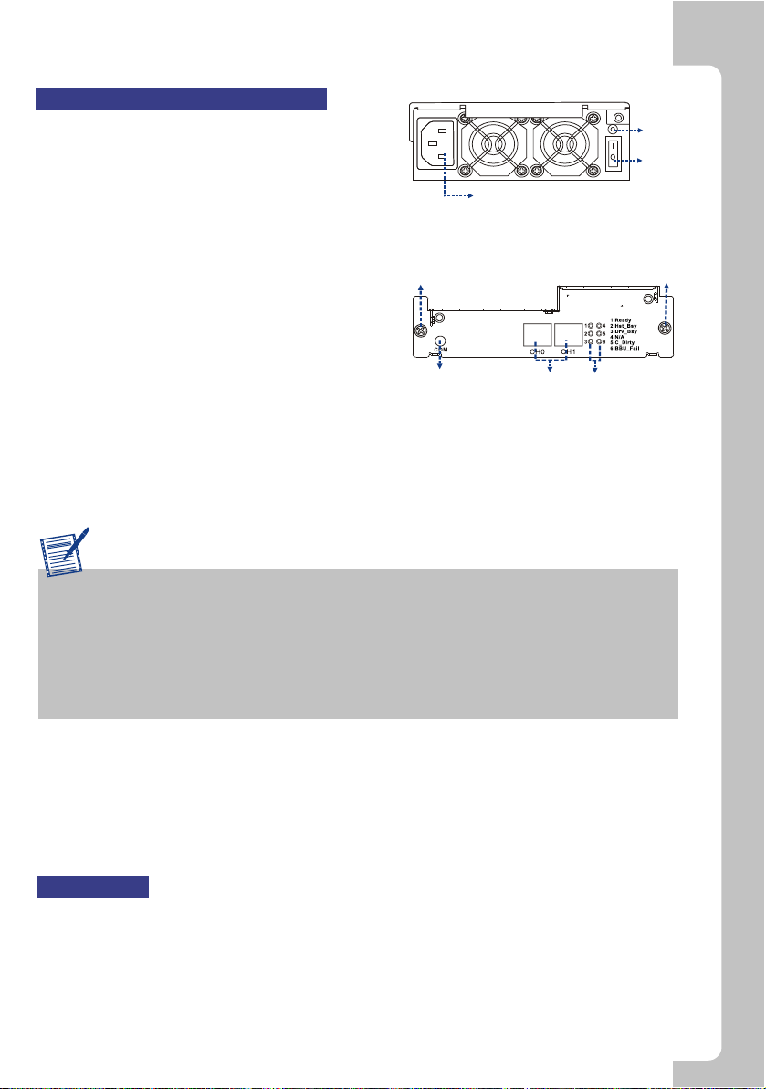
1. Connect thetwo (2) providedpower cords to
the power socketson the backof the system.
(See Figure 5)
2. Make surethe power sourceis within the
correct power range(100 to 240VAC) prior to
powering on.Auto-switching is supportedby
the power supplymodules.
3. Plug theother end ofpower cords intothe
power source.
iSCSI Host Ports
1. Thesubsystem comes withtwo (2) RJ-45
connectors at therear of thecontroller
module. Theycan be connectedto external
network devices oriSCSI initiators, using
standard Cat5e, RJ-45Ethernet cables.The network cablesshould be purchased
separately.(See Figure 6)
2. Attachone end ofEthernet cable tothe subsystem andattach the otherend to the
network devices oriSCSI initiators.
Figure 5:Power Supply Module
Power Socket
Status
LED
Power
Switch
Figure 6:Controller Module
Hand Screw
COM Port RJ-45 Connectors LED Indicators
Hand Screw
Special Notice
Tofacilitate quick configurationof the subsystem,we recommend usingthe Auto
Discovery function providedwith the RAIDWatch Manager software. TheAuto
Discovery tool isbundled with theConfiguration Client utility. Thistool locates
a newly connectedsubsystem without theneed to manuallyassign an IP. For
details, please referto RAIDWatchUser's Manual and itsQuick Installation Guide
that came includedon the ProductUtility CD.
3
COM Port
Each controller modulecomes with one(1) COM port.The portis reserved forterminal
emulation management.This port canbe used toaccess firmware's embedded
configuration utility. One (1)audio-jack to DB9cable and anull modem areprovided to
facilitate the connectionof the COMport. (SeeFigure 6)
Optional Battery Backup Unit (BBU) Installation
The BBU moduleis an optionalitem that mustbe
purchased separately. Prior toinstalling the BBU
module, power off the subsystemor restart the
subsystem after theinstallation. To install theBBU,
please follow theseinstructions:
1. Remove theBBU slot dummyplate by loosening
the two (2)retention screws locatedon both sides
of the platethen pull itout of thechassis. (See
Figure 7)
2. Alignthe BBU modulewith the BBUmodule slot.
Gently insert theBBU module untilthe back ofthe
BBU module reachesthe end ofthe slot. Secure
the BBU moduleto the chassisby tightening the
two (2) retentionscrews on theback of theBBU
module. (SeeFigure 8)
3. If aBBU is addedonline, reset thesubsystem for
the BBU installationto take effect.
Figure 7:Removing the BBU SlotDummy
Plate
Figure 8:Installing the BBUModule
Optional Dongle Kit Installation
The dongle kitis an optionalitem. If youplan to install
PATAdrives in yoursubsystem, you mustpurchase
and install thedongle kits beforeinstalling the hard
drives.
1. Thedongle kit ismounted onto ametal base plate
that has three(3) pre-drilled holesreserved for
retention screws. (SeeFigure 9)
2. Three(3) corresponding pre-drilledscrew holes
are located atthe back ofthe drive tray.
3.Place the donglekit at theback of thedrive tray.
Hold the donglekit in placeand turn thedrive tray
over.Align the holesin the baseof the drivetray
with the holesin the donglekit base tray.
4. Insert thethree (3) providedretention screws from
the bottom ofthe drive tray. Thesescrews firmly
secure the donglekit to thedrive tray andfacilitate
the installation ofthe appropriate drive.(See
Figure 10)
Figure 9:SATA-to-PATA Dongle Kit
Figure 10: Dongle KitRetention Screw
Locations
Power On
Topower on thesubsystem, follow thesesteps:
1. Install allthe hardware components.
2. Make allthe connections describedabove.
3. Power onthe network connectingdevices such asthe Ethernet switches.
4. Power onthe subsystem byturning on bothpower switches onthe rear panelof PSU
modules. For thelocation of thepower switches, pleasesee Figure 5.
5. Power onservers or iSCSIinitiators on thenetwork.