Hydor HHD2500RW User manual

Part No.: INST-HHD2500 02/12
Installation and Maintenance Instructions
THESE INSTRUCTIONS MUST BE READ FULLY BEFORE
COMMENCING INSTALLATION
Code Supply Watts Amps
HHD2500RB
HHD2500RW 230-240V/1Ph/50Hz
230-240V/1Ph/50Hz 2400
2400 10
10
1.0 GENERAL
1.1 It is important these Installation and Maintenance Instructions are fully adhered to.
1.2 Full details of the unit supplied are shown on the product nameplate. If in doubt about any detail
contact HYDOR or its agents for clarification.
1.3 All electrical installation must be carried out by suitably qualified and competent
personnel in accordance with all current statuary requirements.
1.4 Any declarations made by HYDOR about product installation and safety, are
dependant on the hand dryer being used within installations which themselves
meet the requirements of the relevant Standards and Directives of your region.
1.5 The hand dryer must be installed indoors in a dry, sheltered position and is designed for use in
an ambient temperature of up to 40 °C. The hand dryer is not suitable for corrosive or explosive
atmospheres.
1.6 The installer should provide easy access to the hand dryer to facilitate future maintenance.
1.7 The installer should ensure the hand dryer is adequately supported.
1.8 This product is not intended for use by persons (including children) with reduced sensory or mental
capabilities, or lack of experience and knowledge, unless they have been given supervision or instruction
concerning use of the product by a person responsible for their safety. Children should be supervised to
ensure that they do not play with the product.

Part No.: INST-HHD2500 02/12
2.0 INSTALLATION
WARNING – The hand dryer is an IPX1 electrical appliance and must not be installed in
an area where there is any possibility of water ingress. The hand dryer must be isolated
from the power supply during installation and maintenance. The hand dryer must be
earthed in accordance with the local regulations.
2.1 Upon receipt, the hand dryer should be visually inspected to check for any damage.
2.2 Check the details on the rating plate to ensure that the correct power supply (voltage, frequency
and phase) is available.
2.3 An incorrect power supply will lead to permanent damage to the hand dryer.
2.4 Refer to Fig. 4 and remove the cover from the base plate in sequence , , , and . Take
care not to put any strain on the connecting wires between the cover and base plate when
removing the cover.
2.5 Mark and drill 8mm diameter by 35mm deep holes per Fig. 2.
2.6 Attach the base plate to the wall using the screws and plugs provided. Refer to Fig. 3.
2.7 Refer to the appropriate wiring diagram. Ensure that all earth connections are made.
2.8 Means for electrical disconnection must be incorporated in the wiring installation in accordance
with the relevant wiring and electrical regulations.
2.9 Fit the cover to the base plate per Fig. 4. Connect the earth wire to the cover. Connect the
sensor leads. Hook the cover to the top of the base. Push the cover and base firmly
together and fit the socket head machine screws using the Allen key provided.

Part No.: INST-HHD2500 02/12
3.0 START-UP
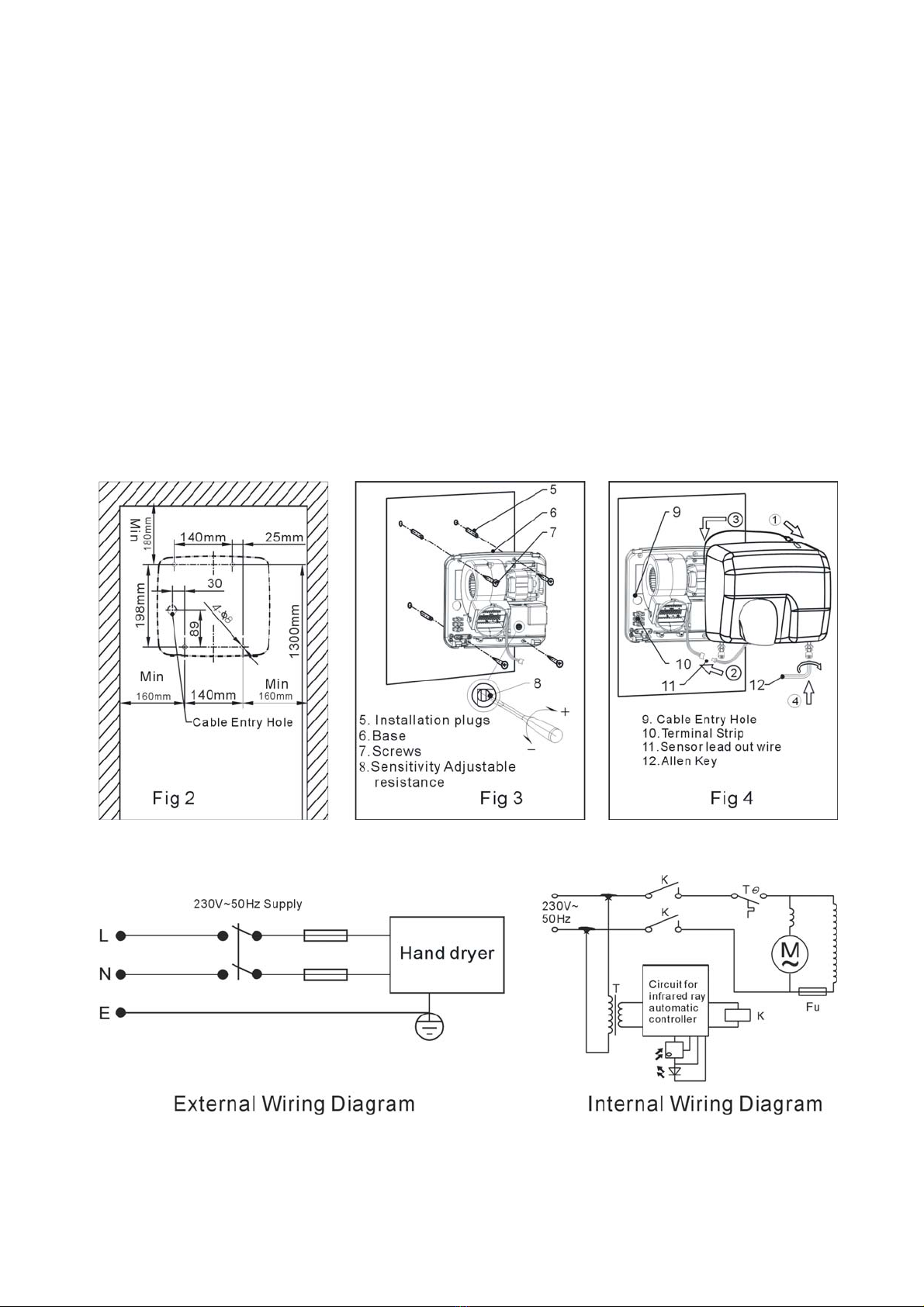
3.1 Before power is supplied to the unit, ensure that the wiring is correct as per the connection
diagram.
3.2 The infrared sensor will automatically activate the hand dryer if movement is detected up to
110mm from the sensor. The hand dryer will stop operating once movement is no longer
detected. The hand dryer will also stop operating after one minute of continuous operation.
3.3 The activation sensitivity can be adjusted per Fig. 3.
3.4 Check that the motor amperage draw does not exceed the nameplate rating.
4.0 FAN MAINTENANCE
4.1 Inspection of the hand dryer at least once every 12 months is recommended to ensure that the
motor, fan blades, and supporting guards, are clean. Any build up of dust and deposits on the
blades or guards should be removed using a non-abrasive cleaner.
4.2 All fastenings should be checked for tightness. In addition, all rotating items should be checked.
4.3 Bearings are of the ‘sealed for life’ type and will not need a detailed inspection.
WARNING – Do not cover the air inlet and outlet. The hand dryer is fitted with thermal protection
which switches the heating element off in the event of a fault condition.
Only a suitably qualified and competent person may carry out maintenance after the electrical
supply has been isolated.
GUARANTEE
HYDOR or its agents will, within a period of 1year from the date of dispatch from their works,
repair or, at its option, replace any goods, which are proven to have defects as a result of
defective materials or workmanship. The goods MUST be returned to HYDOR, carriage paid, for
examination.
Hydor Ltd.
8 Parkers Close, Downton Business Centre
Downton, Salisbury, Wiltshire
SP5 3RB, UK
Hydor Ventilation Aust
42-62 Pound Road West
Dandenong South
Vic 3175
TEL: 1300 655 730 FAX: 1300 134 319 email: info@hydor.com.au
Hydor Ventilation SA
11 Ingrid Road
Montague Gardens
Capetown
7441
Part No.: INST-HHD2500 Issue 7: 6-2-2012
This manual suits for next models
1
Table of contents