HYDROLAB Technical 100 User manual

tel. +48 58 341 16 69
fax. +48 58 585 86 97
biuro@hydrolab.pl
www.hydrolab.pl
2
1. Usage safety
Before connecting and launching the device we advise to read carefully this manual, which includes all important
information about safe installation, usage and maintenance of the demineralizer. This manual should be kept in
case of any issues that might appear during the running process.
1.1 Installation and service
•Every installation and service should be performed by an authorized technician. Installation or service
performed by a person without qualifications can may lead to incorrect system running or be dangerous
for the user.
•Before launching, the demineralizer should be unpacked and checked if it is damaged. In case of any
damage noticed, it should be described in the delivery documentation.
•Service should be performed only by an authorized technician. It is forbidden to perform a service by the
user himself.
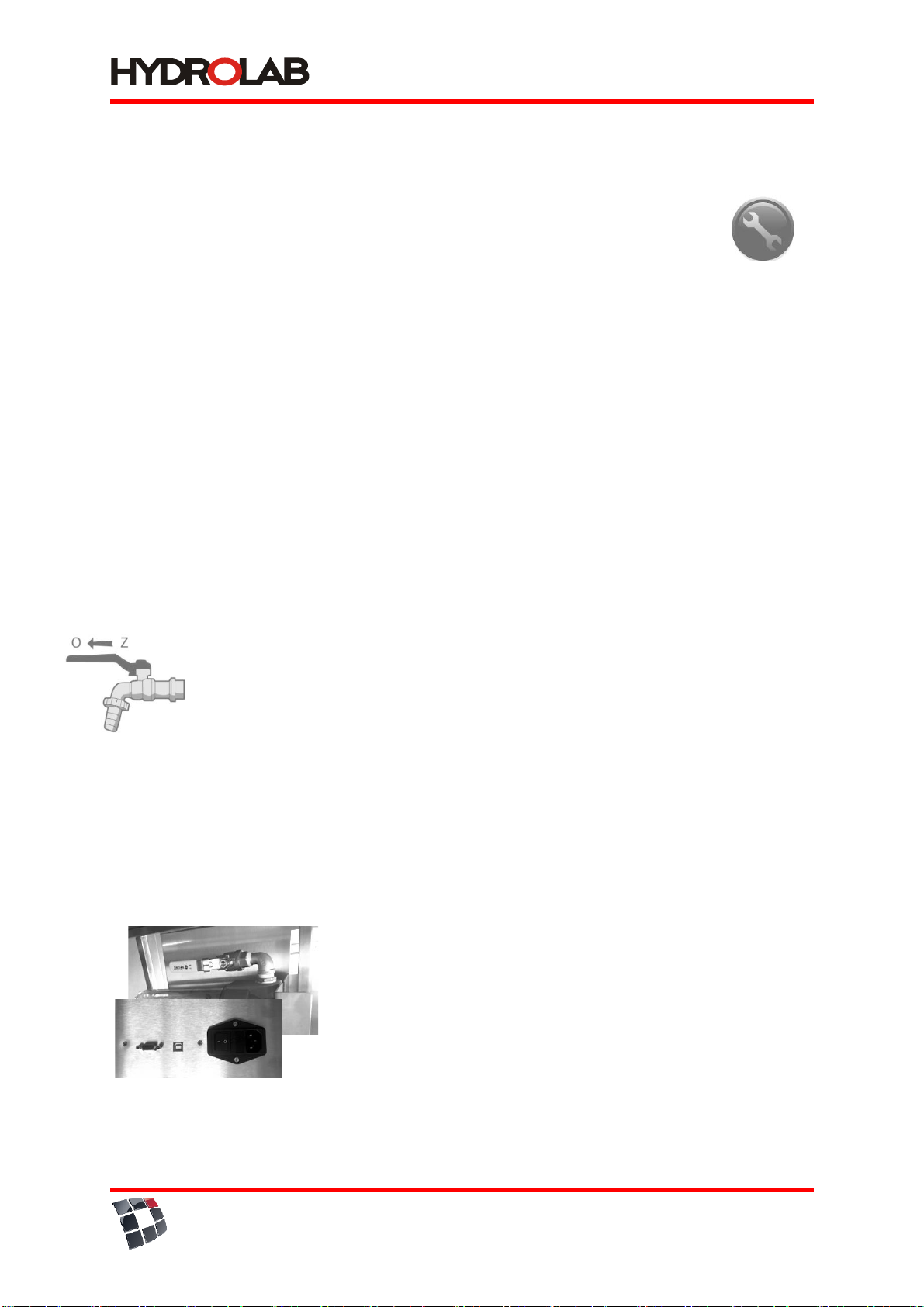
•Before plugging in the device you should close the main valve.
•Water supplying the demineralizer should fit the requirements described in point 1.3. You shouldn't use
water that does not fit the bacteriological requirements or of unknown quality.
•Before plugging in the device make sure, that tension is compatible with the electric network.
•It is forbidden to run the device when the plug, supplying cable or the device itself is damaged.
•While moving the device, watch out for the supplying cable, as it might break or be damaged.
•Warning, the demineralizer is heavy. Be careful while moving it.
•The device and tank should be located in a place with easy access.
•To keep a good lifetime and long-term efficient work, the maintenance should be performed regularly.
•The producer is not responsible for any damages incurred from impropriate device installation.
1.2Supplying water parameters
•Demineralizer devices are intended for purifying tap water.
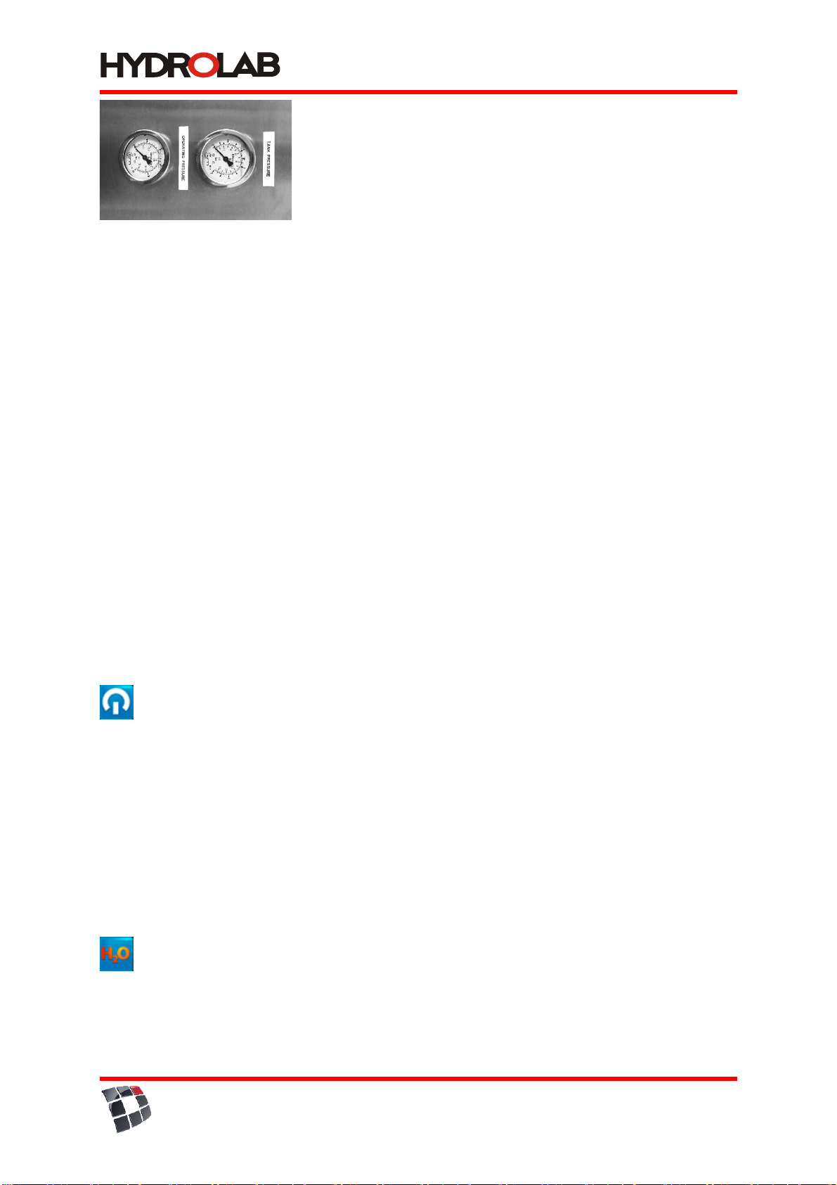
•Pressure –demineralizer can be supplied by water with 3,5 bar (min.) pressure up to 6.0 (max.) bar. If it
is necessary, you should use the reduction valve.
•Temperature –demineralizer should not be situated in locations of high or low temperature. Supplying
water temperature should fit between 4°C and 38°C. Supplying the demineralizer water of temperature
higher than 38°C may damage the device.
•Salinity (TDS) –amount of salts dissolved in supplying water should not excess 900mg/dm3.
•Humidity –relative humidity in the room should not be greater than 80%.
•Water hardness –Water hardness should not be greater than 280 mg CaCO3/dm3.
•Iron –should not be greater than 0,2 mg/dm3.
If any of this parameters is higher than recommended, better preliminary filtration is highly advised. In
that case, you should contact with our service.
1.3 Power supply voltage
•Rated voltage: 220-240V
•Frequency: 50 Hz
•Maximum consumption of power: 4A
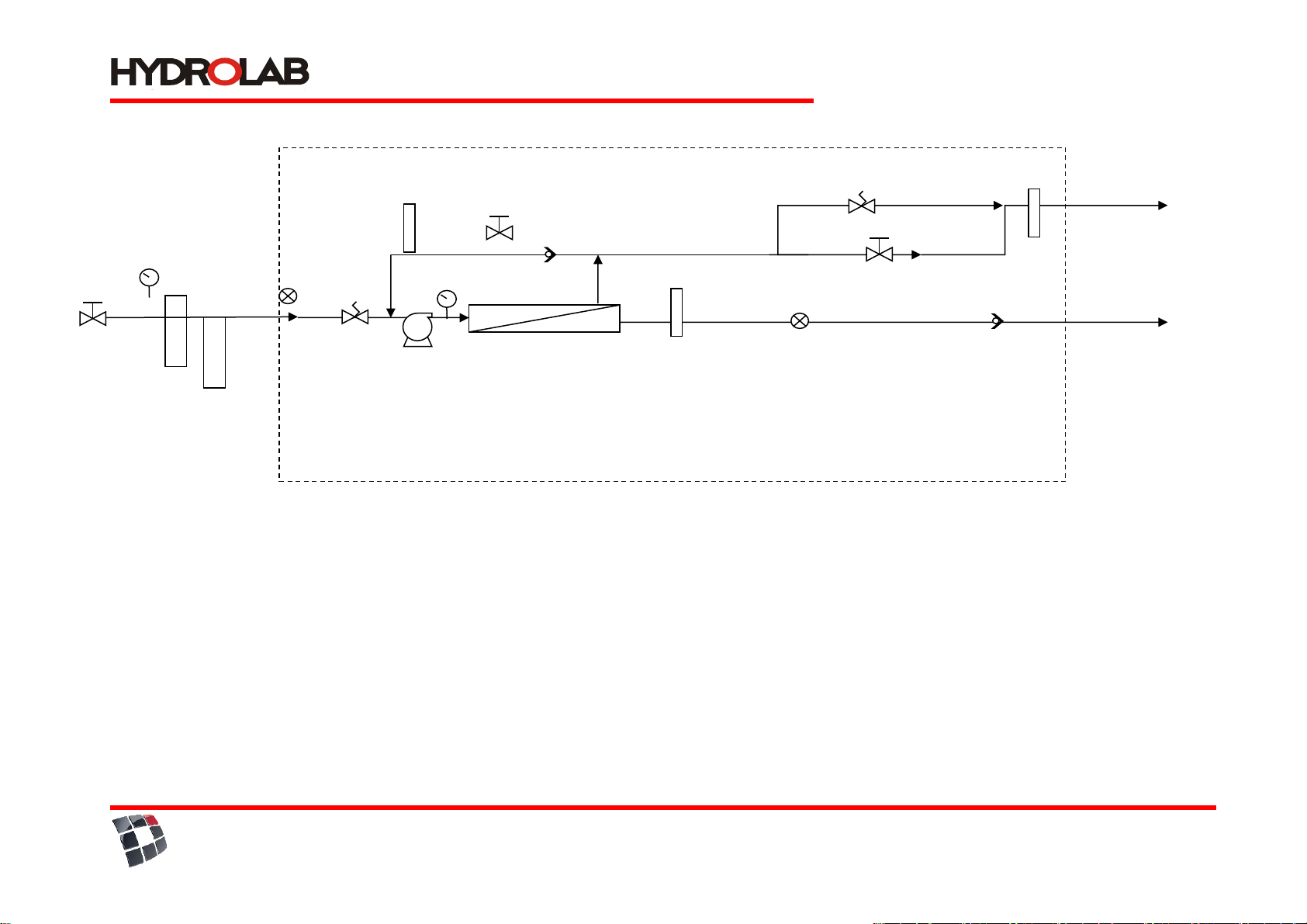
2.General information
TECHNICAL demineralizers are devices perfect for washers, analyzers, autoclaves, environmental chambers,
water baths, as well as, through developing a proper network, supplying several laboratory rooms and
floors. They are fully-automated and maintenance-free.
Allows obtaining third class water, according to PN-EN ISO 3696:1999.

tel. +48 58 341 16 69
fax. +48 58 585 86 97
biuro@hydrolab.pl
www.hydrolab.pl
3
2.1 Operating method
TECHNICAL demineralizer works under the tap water pressure. The purification process is fully-automated and
maintenance-free. It consists of following steps:
1/ mechanical filtration
2/ carbon filtration
3/ reverse osmosis (RO)
5/ UV lamp 254 nm
2.2.1 Mechanical filtration and carbon filter Prefilter
(5 μm) 10" - Residual filter is intended for preliminary filtration, preparing tap water for reverse osmosis. It
consists of a string cartridge made of polypropylene fiber, coiled on the filtration core, which is situated in the
transparent filter housing. It keeps all the mechanical particles with a size up to 5 μm.
Carbon filter 10"–is intended for preliminary filtration, preparing water for reverse osmosis. A filling of the
carbon filter is made of block active carbon put into the housing. Contaminants are sorpted by the active carbon.
2.2.2 Reverse osmosis
RO membrane holds up to 96-99% organic and non-organic contaminants dissolved, as well as heavy metals and
radioactive elements (with a size up to 0,01 micron). Water conduction oscillates around 8-20 μS/cm.
Semipermeable membrane consists of many layers coiled on a perforated pin situated inside the membrane.
Polluted water is pressed on the membrane's surface, where water particles by diffusion penetrate the membrane.
Contaminants are thrown out to the waste-pipe. Purified water gets through holes to the central pin, and under
the pressure, it flows out of the membrane.
2.2.3 UV lamp (option)
UV lamp is used for disinfection. This device emits radiation with 254 nm or 185/254 nm wave
length, which reacts with DNA of bacteria existing in water. UV lamp consists of a expose chamber
containing UV radiator, protected by a removable quartz sheath, mounted inside. In the device
water flows alongside with the lamp, between the housing and the sheath.
3. Technical specification
Dimensions: 1000x700x1500mm
Maximum feed water pressure: 0,6 MPa
Minimum demineralized water pressure: 0,35 MPa
Feed water temperature: 4 –38°C
Device efficiency: 100 dm3/h +/- 10%
Power supply voltage: 230 V + 10%
Frequency: 50 Hz
Maximum operating pressure: 1,3 MPa
This device is equipped with:
•sediment filter 5µm 10",
•carbon filter 10",
•production pump,
•membrane module 4040,
•UV lamp 254 nm or 185/254 nm*,
•conductometer measuring feed and after reverse osmosis conductivity,
•with an alarm informing about necessity to replace disposable materials
•manometer measuring feed water pressure,
•storage tank for purified water*,
•automatic membrane rinsing,
•thermal protection of the membrane module,

tel. +48 58 341 16 69
fax. +48 58 585 86 97
biuro@hydrolab.pl
www.hydrolab.pl
4
•microprocessor control system - ”touch panel”
*option
- valve no. 1 - tap water connection
- valve no. 2 - demineralized water collection point (third class PN 3696)
- valve no. 4 - drain waste point (must not be closed, must always be
unobstructed!!!)
valve no. 1 valve no. 2 valve no. 4

tel. +48 58 341 16 69
fax. +48 58 585 86 97
biuro@hydrolab.pl
www.hydrolab.pl
HYDROLAB Sp. z o.o. Sp. K.
Ul. Wesoła 1
83-010 Straszyn
NIP: 604-015-22-97
3.2 Technical 100 hydraulic schema
ZZ
Feed:
Tap water, P>0,4MPa, x<
1000S/cm
connection 3/4" or 1"
Mechanical –carbon
filtration
Drain waste
ca. 700 - 1000 l/h
RO system pump
RO Modules
4040
Feed
electrovalve
Membrane rinsing
electrovalve
Device area
ZZ
ZO
MRO
MZ
Legend:
MZ –tap water manometer
MRO –RO module manometer
ZZ –return valve
ZO –drain valve
Retentate
rotameter
Permeate
rotameter
Conductivity
measurement
III purity class
Conductivity
measurement
Retentate return
rotameter
valve no. 1
tap water
connection
valve no. 4 - drain waste
point (must not be closed,
must always be
unobstructed!!!)
return control
valve
waste control
valve

tel. +48 58 341.16.69
fax +48 58 585.86.97
biuro@hydrolab.pl
www.hydrolab.pl
HYDROLAB Sp. z o.o. Sp. K.
Wesola 1 str.
83-010 Straszyn
NIP: 604-015-22-97
6
3.1. Materials
All materials used are inert. The most important for the quality of water are materials used after
the second step of the purification process, all the wires are made of polyurethane,
connectors and fittings –polyethylene or PVC,
distributors and filtration nozzles –polyethylene,
conductivity sensor –polyethylene and stainless steel
4. Mounting
−Best results are gained when soft water is used to feed the Spring demineralizer.
−Feed water should fit the requirements listed in 1.3
−Doing the feed water quality analysis allows to choose a proper preliminary purification method
−Cartridge replacement should be performed with a frequency recommended in this manual
WARNING: It recommended to run the demineralizer for at least 15 minutes each day.
4.1 Technical demineralizer installation
It should be remembered to put attached plugs into the wires (which are connected by caps). In case of quick
connectors, just put the flat-cut wire to the connector.
Step 1
Put the device in a suitable place.
Step 2
Supply valve installation.
Because of different local conditions, supplying valve has two reductions: ½” i ¾”.
You should make sure, that the main tap water valve is turned off and water in the feeding pipe is
not under pressure.
You should make sure, that the Technical demineralizer is fed by cold water.
•Step 3
•connect cold water feed to the valve no. 1
•connect the retentate pipe to the drainage
•connect the computer cable to 230V power supply
5. Launching the demineralizer

tel. +48 58 341.16.69
fax +48 58 585.86.97
biuro@hydrolab.pl
www.hydrolab.pl
HYDROLAB Sp. z o.o. Sp. K.
Wesola 1 str.
83-010 Straszyn
NIP: 604-015-22-97
7
Step 1
Check the correctness of every device.
Step 2
Pressure test for checking the leakproofness.
Turn on the supplying valve.
Turn on the "Tap H2O", when water appears –turn off.
Check the demineralizer leakproofness.
5.1 Turning off the demineralizer.
Follow the steps below:
Turn off the power.
Turn off the feed water valve.
Turn off the demineralized water tank valve.
5.2 Operation
Starting the system
•Open the "waste control valve"
•Close the"return control valve"
•Open the feed water valve
•Turn on the power supply 230V
•A production pump and automatic membrane rinsing will begin to operate
•After the automatic membrane rinsing shuts fown (estimated 20 seconds), gradually close the "waste
control valve" until you reach a flow rates between permeate rotameter to retentate rotameter 1:1,5 –
1:2 such that the “operating pressure” stabilizes between 10-12 bar level.

tel. +48 58 341.16.69
fax +48 58 585.86.97
biuro@hydrolab.pl
www.hydrolab.pl
HYDROLAB Sp. z o.o. Sp. K.
Wesola 1 str.
83-010 Straszyn
NIP: 604-015-22-97
8
•Now keep opening the "return control valve" until reaching the “retentate return” flow rate 4-8 LPM,
keeping the “operating pressure” no lower than 8-10 bar.
6. Monitoring functions
TECHNICAL demineralizer has a built-in control system informing about the necessity to replace the filtration
cartridges. It is possible to connect it with a computer, allowing for an individual set of alarm levels and service
frequency. The device is also equipped with a conductometer measuring conduction and temperature of the
reverse osmosis water.
The device also has a manometer measuring feed water pressure. Feed water pressure value indicates whether
the device is working (value equals to the network pressure) or if the tank is full and the device has been
automatically turned off (value equals 0).
6.1 Measuring and controlling panel
Alarms informing the user about necessity to perform maintenance procedures:
•„change prefilter” and a sound signal – informs the user about necessity to replace the sediment-carbon
filters, alarm time is set to 6 months
•„change UV” and a sound signal - informs the user about necessity to replace the UV radiator, alarm time
is set to 12 months - option
6.2 „Touch panel” usage
Turning on/off the panel
Touch the Hydrolab logo to display the main window
Basic mode contains information listed below:
−demineralizer model
−current date and time (top right corner)
−reverse osmosis water parameters
−tank fill level
−active alarms icons
−icons of particular system functions
−sound alarm icon - „speaker”
WATER PARAMETERS
Touch this icon to display the feed water parameters:
- conductivity (in units: µS/cm or MOhm)
- temperature (in ºC)
- tank fill level

tel. +48 58 341.16.69
fax +48 58 585.86.97
biuro@hydrolab.pl
www.hydrolab.pl
HYDROLAB Sp. z o.o. Sp. K.
Wesola 1 str.
83-010 Straszyn
NIP: 604-015-22-97
9
Touch this icon to display the water processed by reverse osmosis parameters:
- conductivity (in units: µS/cm or MOhm)
- temperature (in ºC)
- retention level
- tank fill level
There are three independent levels of conductivity and temperature values of feed, processed by reverse osmosis, and
ultrapure water:
I. blue color – correct value
II. yellow color – warning; values are too high
In case of an alarm occurence the user should:
•turn on the automatic membrane rinsing – in case of an exceeded conductivity value of water processed by reverse
osmosis
If, despite the performed procedures, alarms are still present, the user should contact the service.
III. red color – alarm; value too high
In case of an alarm, the user should:
•turn on the automatic membrane rinsing – in case of an exceeded conductivity value of water processed by reverse
osmosis
If, despite the performed procedures, alarms are still present, the user should contact the service.

tel. +48 58 341.16.69
fax +48 58 585.86.97
biuro@hydrolab.pl
www.hydrolab.pl
HYDROLAB Sp. z o.o. Sp. K.
Wesola 1 str.
83-010 Straszyn
NIP: 604-015-22-97
10
AUTHORIZED SERVICE
Touch this icon to view the contact data to an authorized Hydrolab service
DOSING (OPTION)
Touch this icon to collect water
The user can input to the system memory 3 values of dosed water volume:
To set the volumes (separately for 1, 2, and 3) touch the icon „key”.
Touch „start” – measure the water volume, and press „stop”.
INFORMATION
Touch this icon to view the maintenance deadlines of particular disposables:
- integrated module
- UV lamp radiator (option)
ALARMS
Touch this icon to get information about active alarms:
The user is also informed about:
- too low (<4ºC), or too high (>40ºC) water temperature
- current system status, for instance „filling the tank”
MEMBRANE RINSING
Touch this icon to perform the membrane rinsing
TURNING ON/OFF THE SOUND SIGNALS
To toggle the sound signal of active alarms, touch the „speaker” icon
6.3 Functions protecting the operation process
Demineralizer automatically turns on when the demineralized water is provided, and works until a full
replenishment. When the tank reaches a proper pressure, the device is automatically turned off. Technical
demineralizer is equipped with a membrane pump, and low/high pressure sensors. It allows operating without
necessity to constant maintenance of the device. The demineralizer is automatically turned off when:
−the pressure is too low
−the tank is full
−there is no water feeding the device
7. Maintenance
This system uses disposable materials listed below:
•sediment filter 5µm 10",
•carbon filter 10",
•UV lamp 254 nm *,
*option

tel. +48 58 341.16.69
fax +48 58 585.86.97
biuro@hydrolab.pl
www.hydrolab.pl
HYDROLAB Sp. z o.o. Sp. K.
Wesola 1 str.
83-010 Straszyn
NIP: 604-015-22-97
11
7.1 Preliminary filter replacement
Preliminary filters: 5 μm, carbon filter 10”
Frequency of replacement depends on amount and quality of water. For the hygienic purposes, the
control should be performed at least once per 6 months. This can be performed by a user himself.
About necessity to replace the preliminary filters a user is informed by the control system on the display
screen. Information appears on the screen ("change prefilters") and there is a sound signal.
Step 1
Turn off the device (5.1) and close the feed water valve.
Step 2
Replacement of a 5 μm pre-filter (s1):
•Twist off the filter body using a hand or a key
•There is a rubber seal in the body –don't lose it
•Remove the filtration cartridge and put in a new one
•Tighten up the head to the body until a delicate resistance, and then a bit more.
Step 3
Replacement a block carbon:
−Open the device's back
−Remove the filtration cartridge and put in a new one
−Close the back
Step 4
−Open the feed water valve
−Check the leakproofness
−Press the "reset" button
7.4 UV radiator replacement*
WARNING: the radiator is very fragile!
Step 1
−Turn off the device
−Close the tank Valle
Step 2
Disconnect the lamp from the power supply.
Take out the rubber cover and carefully slide out the radiator. Disconnect the power
supply cable from the radiator and remove the radiator from the housing.
Step 3

tel. +48 58 341.16.69
fax +48 58 585.86.97
biuro@hydrolab.pl
www.hydrolab.pl
HYDROLAB Sp. z o.o. Sp. K.
Wesola 1 str.
83-010 Straszyn
NIP: 604-015-22-97
12
To mount a new radiator, take it carefully from the box –don't touch the transparent surface (in case
of dirt –clean it with alcohol). Slide it in carefully into the quartz sheath (1), connect the power supply
cable and pull it into the rubber cover on the aluminum sealing cap (2). Secure the cap. (3.1 –3.2)
Check the grounding –green wire should be connected with a bolt located on the side of the device.
Step 4
−Open the feed water valve.
−Check the leakproofness.
−Open the tank valve.
Step 5
Connect the lamp to the power socket.
7.5 Replacing the RO module
RO module works for 4-5 years (assumption –it depends on the quality of feed water).
The membrane cartridge lifetime may differ, depending on the flow, its character and type of
contaminants.
Symptoms of imperfect membrane module work:
−slower flow,
−lower efficiency.
A replacement of the RO module is performed by an authorized service of Hydrolab.
7. Work safety regulations
Conditions of the location and other issues concerning the device may be regulated by certain law acts
and bills.
You particullary should not:
−touch the switches with wet hands,
−touch the pressure wires with sharp tools
8. Malfunctions in the device operation
Some of them may occur because of not performing simple maintenance or oversights and may be
easily fixed by a user himself without necessity to call the service. Unnecessary service call is chargeable,
even during the warranty.
WARNING: don't try to fix the device by yourself. Repairs performed by unqualified individuals may cause
a serious damage to the device and be dangerous to user's safety.
10. Service
Date
Service
Subject
Signature
Comments
Table of contents
Other HYDROLAB Water System manuals
Popular Water System manuals by other brands

Steinbach
Steinbach 49105 instruction manual

IXOM
IXOM Medora GridBee GF5000 owner's manual

AmeriWater
AmeriWater CENTURION 1500+ instructions

GENERAL ECOLOGY
GENERAL ECOLOGY 770103 AC-2-1 CRS Maintenance manual

Everpure
Everpure Wrap ScaleStick EV9799-06 Specification sheet

Kenmore
Kenmore 625.385560 UltraFilter 650 owner's manual

Taylex
Taylex ABS4200 installation manual

Cetetherm
Cetetherm AquaEfficiency EFF76 DD Installation, service and operating instruction

ATS
ATS DWS Series Installation & operation manual

Frigicoll
Frigicoll Kaysun Aquantia R-32 PRO Installation & owner's manual

ITT
ITT LX Series Installation and operating instructions

Ispring
Ispring WCC31 user manual