HydroMist Pro Series User manual

Table 1
Pro Series
Misting Pump
Operating Manual

1.1. Specifications and Basic Functions
1.2. Dimensions
1.3. Identifying the Components
2 - Quick Set-up
2.1. Installing the Machine
3 - Correct Use
4 - Operating Guide
4.2. Control Panel Functions
4.3. Overview of the LCD Monitor
4.4. Misting Controller Operation
5 - Troubleshooting
6 - Maintenance Guide
7 - Periodic Checks and Inspection
8 - Product Warranty
Table Of Contents
1 - Overview
------------------------------------------------------- 02
----------------------- 01
------------------------------- 03
---------------------------------------------------------- 06
07
08
----------------------------------------------------
-------------------------------------------------
17
17
--------------------------------------------------- 21
09
----------------------------- 10
2.2. Pro II Diagram
2.3. Infrared Remote Control
----------------------------------------------- 04
------------------------------------
-----------------------------
4.1. Control Box Specifications -------------------------------
---------------------------------- 05
---------------------------------- 20
------------------------------------- 04

1 - Overview
1
Model
Pro 75 (F10-04-007) Pro 100 (F10-04-008)
Max. Pressure
1000 PSI / 70 BAR
Pro 75
0.72 gpm @ 1750rpm
Single Phase Induction Motor 120V/60Hz
Pro75 = 3/4HP Pro 100 = 1 HP
L x W x H
21.7 x 13 x 14.6 in.
Net Weight
Pro 75 : 60 lbs Pro 100 : 62 lbs
·
·
·
·
·
·
Electric Solenoid Valve, Inlet
Electric Solenoid Valve, Outlet
LCD Control Panel
5” Particulate Filter
Water Supply Sensor
Infrared Remote Control
Notice
Do not use the pump during adverse weather conditions.
1.1 Secifications and Basic Functions
Flow Rate
Electric Motor
Standard
Components
Functions
·Automatic Shut Off if Water Supply Fails
·Motor Overload Protection (Breaker Switch)
·Temperature & Humidity Sensing
·Total Run Time Counter
·300 Hour Maintenance Reminder
·Pressure Regulator with Internal Bypass
·Mode 1:15 sec. Misting / 20 sec. Stop
·Mode 2:25 sec. Misting / 30 sec. Stop
·Mode 3:40 sec. Misting / 40 sec. Stop
·Mode 4:Custom Programmable
·Mode 5:Weekly Cycle (set by user)
·Mode 6:Continuous Misting
Pro 100
0.95 gpm @ 1750rpm

14.6
13.3
22.5
1.2 Dimensions (inches)
2

1
3
5
6
7
8
2
4
3
2
1
1LCD control Panel 5Pressure Gauge
2Carry Handle 61/4" Connector, Outlet
3Sensor for Temp. & Humidity 7Hose Coupler, Inlet
4Power Cable with Plug 85”Inlet Water filter Housing
1
Power Cable Port
3Motor Overload Breaker Reset
2
Main Power Button
Table
2
Table
1
1.3 Identifying the Components
3
CAUTION:
The Power Cable provides electricity into the pump housing.
If the power cable is plugged in there is elecricity present inside of the machine.
ALWAYS UNPLUG THE POWER CABLE BEFORE OPENING THE CABINET ACCESS PANEL.

2 - Quick Set-up
2.1.1 Unpack the Machine
2.1.1.1 Remove the pump from the box
and verify all accessories present. Check
the machine to see if there is any
damage.
2.1.2 Install the water supply line 2.1.2.1 Connect a garden hose to the
inlet fitting securely.
2.1.2.2 Connect the hose to a water supply.
2.1.2.3 Pressurize and check for leaks before
turning on the pump.
2.1.3 Connect the outlet to misting system.
2.1.4 Connect the electrical power
2.1.3.1 Connect a high pressure misting
fitting to the 1/4" NPT brass outlet
fitting on the machine.
2.1.3.2 The outlet port has an built in ball valve.
It is used to vent any air trapped inside
the pump. You may need to initially
vent the air using this valve. Close the
valve when a steady stream of water
flows out, and the pump will pressurize
to full operating pressure.
2.1.4.1 Verify the voltage and current
requirements before plugging the
power cable into the socket. Push
the main power button to “ON”.
2.1 Installing the Machine
4

2.2 Misting System Diagram
1
2
3
4
1Power Cable
2PRO II Misting Pump
3Water Supply Hose
4Misting Nozzle Circuit
A Basic Diagram of Misting System
1START key
2STOP key
Function Keys for Remote Control
Stop
Run
1
2
2.3.1 Attach the provided remote control holder onto a wall or
other location with the included screw.
2.3.2 Remove the plastic cover on the back of the remote
control unit. Install 2 AAA batteries into the unit and
reinstall the cover.
2.3.3 Put the remote control unit in the holder when not in use.
2.3 Infrared Remote Control
55
2.3.4 The ideal distance to use the infrared remote control
is within 15 feet. The remote must have a direct line of
sight for successful operation. Direct sunlight can
decrease the effective range of the infrared remote.

3.1.1
The pump should not be powered on during adverse weather conditions
(such as rain, electrical storm, flood, or other dangerous weather).
3.1.2
Only trained operators should use the pump. Children and adults who are
not trained should be restricted from operating the machine.
3.1.3
Power sources must be equipped with proper grounding and circuit
breakers. The National Electric Code, or your local municipal building
code, may have special requirements for installations of this type of
equipment (such as GFCI receptacles for wet locations).
3.1.4
Do not operate the pump in or below freezing temperatures (32°F / 0°C)
3.1.5
Do not move or operate the machine in excessively wet environments.
3.1.6
Place the machine on cement or another solid, flat surface that provides
a firm level support to all four feet of the pump. Keep the machine and
its surroundings dry. Keep the pump away from flammable gases or
fumes. Sparking and excessive heat can ignite flammable gases,
liquids, or materials.
3.1.7
Always read the entire manual before operating the pump. Consult a
professional if you are unable to successfully complete installation.
3 - Correct Use
6
3.1 Attention
3. 2 CAUTION
3.2.1
Before starting the machine, verify that oil is present inside of the pump.
3.2.2
Connect only to a power source with correct electrical voltage (V),
frequency (Hz), and adequate current supply according to machine's
specifications.
3.2.3
Do not increase the operating pressure of the pump over 1000PSI.
3.2.4
Do not run the pump without an adequate water supply. Insufficient water
supply will damage the components inside the pump and significantly
shorten the life of the machine.
3.2.5
During operation, do not open the cover and do not touch either the
motor, the pump, components, or wires. Risk of burns or electrocution is
possible. If you plan to service the pump, disconnect the power.
3.2.6
Before running the machine, visually inspect the wires, hoses,
components, and connections for any abnormal wear or breakage.

3.3
Operational Notices
4 -
Operating Guide
4.1.1 Acceptable power sources include AC 100V-240V, 50Hz or 60 Hz.
4.1.2 Ambient Temperature must be between 32-120oF and relative
humidity between 5% - 95%.
4.1.3 Internal power for controls is DC 12V.
4.1.4 3 relays control the functions.
RY1:drives the electric motor.
RY2:drives the inlet solenoid valve.
RY3:drives the by-pass solenoid valve
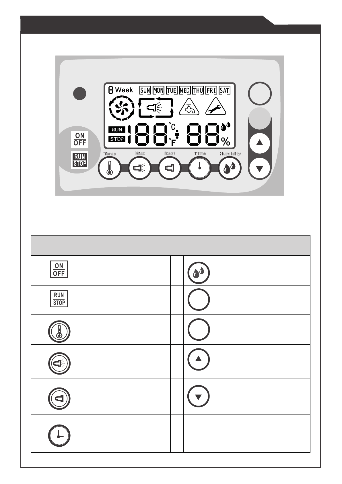
4.1.5 Blue back-light LED screen.
4.1.6 Infrared transmission remote control.
4.1.7 RTC time control, programmable.
4.1.8 6 operating modes available.
4.1.9 Both Celsius and Fahrenheit systems are available.
4.1.10 Detecting function for humidity.
4.1.11 Buzzer/alarm for timer.
7
4.1 Control Box Specifications
3.3.1
The water supply hose must be at least 3/8" size garden hose.
3.3.2
3.3.3
Verify the flow rate for water supply is at least 1 gpm. The water pressure at pump
inlet should be at least 40 PSI.
3.3.4
Water temperature must not exceed 140 oF, and must be well-filtered. Poor water
quality will decrease the service life of the pump and components.
3.3.5
Where applicable, install a pressure relief device in the event that excess pressure
over 1500 PSI occurs in the misting system.
3.3.6 A valve installed at the end of a misting system is recommended. It will help purge
the system of air inside the pipes or lines. This can also be useful to flush lines before
winter weather to prevent freezing water damage due to expansion.
3.3.7 When misting, check all nozzles and ensure none are blocked. If blocked,
clean or replace the damaged nozzle.
Check that all connections are watertight ant not leaking. Leaking connections
will decrease the system pressure and affect misting nozzle performance.
For winter storage, run the pump, shut off the water supply, and allow the pump to
shut off due tothe inlet water sensor. Remove water from filter housing and purge
any lines or pipes connected to the high pressure side of the misting system.
Extension cables should not be used to power the unit. If necessary, keep the cable
length below 25 feet, and use an adequately rated cord designed for outdoor use.
3.3.8
3.3.8

RUN/STOP Current Program 8Mode Change Button
Temperature Control Button 9Enter Button
Mist ActivateTime Setting
Button 10 Up Button
ON/OFF Control Panel Power 7Humidity Control Button
Rest Time Setting Button
Time Button
11 Down Button
Rest
Mode
Time
Enter
Mist Rest HumidityTemp
1
Guide of Function Keys
Temp
Time
Mode
4.2 Control Panel Functions
Enter
2
3
4
5
6
8
Mist
Humidity

1
3
4
5
6
7
89
10
11
12
13
14
2
1Week Schedule 8Display Units (Celsius/Fahrenheit)
2Displays the Mode Selected 9Numerical Value (Humidity/Time)
3Display for 1st Time Interval 10 % (When Humidity Value)
4Display for 2nd Time Interval 11 Displayed When
Maintenance is Required
5Displays During Running 12 Insufficient Water Supply Symbol
6Displays When Stopped (Standby) 13 Weekday Selection
7Numerical Value (Temp./Time) 14 Display indicator for Misting/Rest
Introduction of the LCD Monitor
4.3 Overview of the LCD Monitor
9

4.4.1 Remote Controller, Buzzer, Function Keys
4.4.1.1 Push the ON/OFF button once to turn on the control screen (the
water sensor alarm will sound until water is supplied to the pump
inlet). Push the button again to turn off the control screen.
4.4.1.2 With the control screen on, pressing the RUN key on the
remote control will activate the current program.
4.4.1.3 With the pump running, pressing the STOP key on the
remote will stop the current program.
4.4.3
ON/OFF-Key: (not the main external power supply switch)
4.4.3.1 When pump is standing by with power on, pressing the ON/OFF button
will turn off the LCD screen on the control panel. The control panel is off.
4.4.3.2 When the machine is powered off, pressing the ON/OFF button will power
on the LCD screen and the control panel is active.
4.4.3.3 The ON/OFF button will shut down the pump even if the external
power supply switch is on.
4.4 Misting Controller Operation
10
4.4.2 Power On and LCD Backlight
4.4.2.1 After pressing the ON/OFF button, the back light of the LCD is on for 3 seconds.
4.4.2.2 After powering on the control panel, the back light will turn off after 30
seconds if no further operation is executed.
Note: Before turning off the main power switch or LCD control box, it is
recommended to stop the unit from running. Abnormal shutdown
procedures can result in pump damage over time and should be avoided.
4.4.4 RUN/STOP-Key
4.4.4.1 With machine standing by, push the RUN/STOP button to activate the
current program. The LCD wil show a“RUN” indicator.
4.4.4.2 While the machine is running, push RUN/STOP to stop the program.
LCD shows a“STOP”indicator.
4.4.5 MODE-Key
4.4.5.1 When the pump is running, this key does not work.
4.4.5.2 When the machine is in the status of STOP, the user can push the
MODE key and revolve the mode in 1→ 2→ 3→ 4→ 5→ 6 sequence.
Mode

4.4.6 ENTER, UP, and DOWN Keys
4.4.6.1 Select a function key to set the mode/function, push UP key and/or
DOWN key to adjust the value, then push ENTER key to confirm the selection.
4.4.7 TEMP-Key:( The default setting is off )
4.4.7.1 When the machine is in STOP status, push the key one time to activate
or disable temperature monitoring function.
Push the key to revolve the mode. Example:
Activate Temp Monitoring →Disable Temp Monitoring → Activating Temp monitoring ...
When users activate the temperature monitoring function, the numerical
value shows and the“oC or oF ” flashes.
When users disable the temperature monitoring function, the numerical
value still shows, but the “oC or oF ” is steady (not flashing).
4.4.7.3 With machine in STOP status, push the key for 3 seconds and LCD
will show flashing numerical value for “oC or oF”. Adjust the
temperature setting by pushing UP or DOWN keys.
Push UP-key:10→11→12→……→60
Push DOWN-key:60→59→58→……→10
4.4.7.4 After selecting the temperature, either push TEMP key or
wait for 15 seconds to confirm the setting.
4.4.7.5 The temperature monitoring function works as below:
When the ambient temperature reading is less than the set
temperature (+/- 2 degrees), the numerical value will flash and the pump will not
run until the temperature rises above set value.
4.4.7.6 The setting range is between 10 oC (50 oF) ~ 60 oC (140 oF) and
default value is 29 oC (84 oF).
4.4.7.7 The highest sensable temperature is 65 oC (150 oF).
4.4.7.8 The temperature monitoring function applies to all modes.
4.4.8 HUMIDITY-Key:( The default setting is off )
4.4.8.1 When the machine is in
STOP status, push the HUMIDITY key to activate or
disable humidity monitoring function.
Push the HUMIDITY key to revolve the mode. Example:
Activate Humidity Monitoring → Disable Humidity Monitoring→ Activate Humidity Monitoring...
11
Enter
4.4.7.2 Temperature monitoring display is shown as follows:

4.4.8.2 Humidity monitoring display is shown as follows:
When users activate the humidity monitoring function, the
numerical value is shown and the“%” indicator flashes.
When users disable the humidity monitoring function,
the“%”indicator will be steady (not flashing).
4.4.8.3 When the machine is in STOP status, push the
key for 3 seconds and
the numerical value and the“%”indicator will will flash on the LCD.
Adjust the humidity setting by pushing UP or DOWN keys.
Push :30→35→40→……→95
Push :95→90→85→……→30
4.4.8.4 After setting the humidity value, either push HUMIDITY key one time or
wait for 15 seconds to confirm the setting.
4.4.8.5 The humidity monitoring function works as below:
The temp monitoring function is prior to humidity monitoring function.
When the ambient humidity is equal to or lower than the set humidity
(+/- 3%), the pump will activate.
When the ambient humidity is higher than the set humidity value, the
numerical value will flash and the pump will stop running until the
humidity reading decreases to below the humidity set value.
4.4.8.6 The setting range is between 30% ~ 95%. The default humidity is 70%.
4.4.8.7 The humidity monitoring function applies to all modes.
4.4.9 MIST-Key
4.4.9.1 When the machine is in
STOP status, select mode 4 to customize mist interval.
4.4.9.2 Set “Minute” by pushing UP or DOWN keys.
Push :00 -> 01 …-> 57-> 58-> 59
Push :59 -> 58 …-> 02-> 01-> 00
4.4.9.3 After setting the “Minute”value, push ENTER for“Second” setting.
Set the value pushing UP or DOWN keys
Push :00 -> 01 …->57->58->59
Push :59 -> 58 …-> 02-> 01-> 00
Note:If the ”Minute” is set as 0, the setting interval for “Second” is
15 sec.
4.4.9.4 The MIST image
will be visible to indicate a misting status.
4.4.9.5 Push MIST key one time or wait for 15 seconds to confirm and quit the
setting.
4.4.9.6 The default value is 【One minute】and 【Zero second】.
12

4.4.11 TIME-Key - The controller uses
a 24:00 hour clock format.
4.4.11.1 At any time, the LCD will show the time when you push the TIME
key.
4.4.11.2 When the LCD is showing time, push the TIME key once or wait
15 seconds, the system will go back to show temperature and/or
humidity again. When the machine is in STOP status, push TIME key to
show the time and then ENTER key to set the time.
Push the ENTER key and revolve the module in WEEK → HOUR→
MINUTE →WEEK... sequence.
4.4.11.3 Push UP key to cycle values, as shown below:
Week:SUN → MON → TUE → WED → THU → FRI → SAT →SUN
(in sequence)...
Hour:00→01→02→…→23→00...
Minute:00→01→02→…→59→00...
4.4.11.4 Push DOWN key to decrease value progressively, as below:
Week:SUN → SAT → FRI → THU → WED → TUE → MON →SUN
(in sequence)...
Hour:00→23→22→…→01→00...
Minute:00→59→58→…→01→00...
4.4.11.5 Push TIME key one time or wait for 15 seconds to confirm and quit the
setting.
4.4.10 REST-Key
4.4.10.1 When the machine is in STOP status, select mode 4 to set the rest time.
4.4.10.2 Set “Minute” by pushing UP or DOWN keys.
Push UP key:00 -> 01 …->57->58->59
Push DOWN key :59 -> 58 …-> 02-> 01-> 00
4.4.10.3 After setting the “Minute”, push ENTER for“Second” setting.
Set the value pushing UP or DOWN keys
Push UP key :00 -> 01 …->57->58->59
Push DOWN key:59 -> 58 …-> 02-> 01-> 00
4.4.10.4 The REST image will be visible to show non-misting (rest) period.
4.4.10.5 Push REST key one time or wait for 15 seconds to confirm and quit the
setting.
4.4.10.6 The default value is 【One minute】and 【Zero second】.
13

4.4.13 MODE 5 - Weekly Cycle Setting
4.4.13.1 When the machine is in STOP status, push TIME key for at least 3 seconds
to set the weekly cycle.
4.4.13.2 Set demand period (total 14 periods) by pushing UP or DOWN keys.
The selected “weekday” will flash with brackets around the selected day.
The periods revolve in a sequence as shown below
SUN→ → →MON→ → →TUE...
Whenever selecting a specified period, the system will show RUN
and STOP settings alternating back and forth.
4.4.13.3 Push ENTER key to start the setting procedure for the specified period.
4.4.13.4 Push UP and DOWN keys to adjust“Hour”of run time, and the
numerical time value with flash during setting. Press ENTER to confirm.
4.4.13.5 Push UP and DOWN keys to adjust“Minute”of run time, and the
numerical time value will flash during setting. Press ENTER to confirm.
4.4.13.6 Push UP and DOWN keys to adjust“Hour”of stop time, and the numerical
time value will flash during setting. Press ENTER to confirm.
4.4.13.7 Push UP and DOWN keys to adjust“Minute”of stop time, and the
numerical time value will flash during setting. Press ENTER to confirm.
4.4.13.8 Save the setting and return to 4.4.13.2. to select another weekday and
period.
4.4.13.9 There are two periods for every weekday. Period 1 , Period 2 .
Mode
14
4.4.12 Definition of Misting Modes 1 to 6
4.4.12.1 Mode 1:Misting 15 sec. and rest 20 sec.
4.4.12.2 Mode 2:Misting 25 sec. and rest 30 sec.
4.4.12.3 Mode 3:Misting 40 sec. and rest 40 sec.
4.4.12.4 Mode 4:Programmable, refer to 4.4.9. and 4.4.10.
4.4.12.5 Mode 5:Weekly cycle set by user.
4.4.12.6 Mode 6:Continuous Misting.

4.4.13.10 The setting RUN and STOP data will not be saved, until both periods are
set. Any time, when users push TIME key or wait for 15 seconds without
setting new value during the setting procedure, system will neglect
current setting.
In order to save current settings, the time of weekday RUN and STOP
periods must be set. Cycle back to weekday (brackets around weekday
flashing) and press TIME key or wait for 15 seconds to save the setting.
The whole setting procedure is as below:
SUN (whatever day) → RUN/STOP → Period options → HOUR setting
→ MINUTE setting → SUN
4.4.13.11 When Mode 5 is active, the machine displays a "5" for the mode status.
4.4.13.12 The LCD will show "WEEK X" where "X" stands for the current mode
number (0,1,2, 3,4, or 6) within the mode 5.
4.4.13.13 When both Period 1 and Period 2 are selected, Period 1 is prior to Period 2.
4.4.13.14 Attention:If the mode is selected as 0 in a specified period, the machine
will not be activated.
06:00
10:00
12:50
18:00
1
4.4.13.15 The default values the manufacturer has set:
Mode 1 1 1 1 1 1 1
DAY SUN MON TUE WED THU FRI SAT Note
Period 1
08:00
∫
11:30
08:00
∫
11:30
08:00
∫
11:30
08:00
∫
11:30
08:00
∫
11:30
08:00
∫
11:30
08:00
∫
11:30 Time of the
period and
mode can
be set by
user
Mode 1 1 1 1 1 1 1
Period 2
13:30
∫
17:30
13:30
∫
17:30
13:30
∫
17:30
13:30
∫
17:30
13:30
∫
17:30
13:30
∫
17:30
13:30
∫
17:30
15
Priority of the time periods within a day.
MODE
1
MODEMODE
2
MODE
2

Mode
4.4.15 Service Mode - Display units and service reset.
4.4.15.1 When the machine is standing by, push , at the same time for
3 seconds, then the system enters into the service mode.
4.4.15.2 When you push the ENTER key, the options of service mode
revolve as follows: 1 → 2 → 3 → 1... in sequence.
4.4.15.3 During service mode, the system will go back to the normal
operating modes if you push MODE or wait 15 seconds.
4.4.15.4 When total running time reaches 300 hours, the maintenance icon will
illuminate and the alarm will sounds. The action will not influence any
functionality, but maintenance should be performed at this time.
4.4.15.5 To reset the Maintenance Warning Icon, after maintenance, enter into
service mode, go to mode 2, push DOWN key 3 seconds to turn off the
warning.
Mode Description Setting Procedure
1Celsius / Fahrenheit Push TEMP key one time to switch Celsius / Fahrenheit
system. After the change, the temperature monitoring
units will alter accordingly.
2Total Running Time
for Motor Push DOWN key 3 seconds, then the existed running time
will be eliminated (normally, reset after maintenance).
3
Sum of the Total
Running Time of the
System
The sum value can't be reset. If the user changes a
machine's motor or pump, please check with the
manufacturer to reset the total running time sum.
Operating Mode
4.4.14 Insufficient Water Supply Warning
4.4.14.1 When water supply is insufficient, the warning icon will flash and
the alarm will sound. The alarm will continue to sound and the pump will stay
stopped until water is supplied to the inlet.
4.4.14.2 In order to relieve the WARNING, please check and eliminate the
insufficient water supply condition. The system will automatically detect
the inlet water pressure and the alarm will stop, allowing the machine to
operate normally.
16

17
5 - Troubleshooting
No mist
comes out of
nozzles
• Misting nozzle worn out.
• Clean the nozzle, If it doesn't
work, change the nozzle.
•Purge air from system.
• Tighten all joints connected to the
water inlet.
• Check inside pump cabinet for
leakage and repair if necessary.
The pump fails to
pump water
Unstable output
pressure
Abnormal noise or
vibration
Oil or water leaks
• No water supply.
• The misting nozzle is blocked.
• Air exists in the system.
• Air inside the pump.
•Valves worn out or the pump
cavity is clogged.•Have the valves cleaned or
replaced.
• Change misting nozzle.
•Valves worn out or the pump is
clogged.
• Air inside the pump.
• The water filter is blocked.
• The seals or packings inside the
pump are worn out.
• The pumpss regulator can be
worn out or get stuck.
• The pump's valves worn out.
• The seals or packings inside the
pump are worn out
•Low oil level
•Misting lines or nozzles blocked
• Water supply (including
inlet pressure) is abnormal.
• Turn on the water faucet.
• Change or clean the valves, then
reset the pump.
• Tighten all joints connected to the
water inlet.
•Purge air at the brass outlet
fitting. Close valve and retry.
• Clean or replace water filters.
• Replace the worn out seals or
packings.
• Dismantle the regulator, clean
and/or change related parts if
necessary.
•Clean or change valves.
• Replace the worn out seals or
packings.
• Add or change oil
• Clean or change nozzles, lines,
and/or water pipes.
• The voltage of the power supply is
not stable.
• The power wire extends too long,
and causes voltage and current
drop.
• The built-in thermostatic
switch (breaker) activates to
protect the motor.
• The settings of the control
panel prevent motor operation.
• Apply a constant voltage regulator
and/or shorten the extension of
the power cable. Try a different
power supply.
• Replace the worn out or damaged
seals or gaskets.
•Check the operating pressure is
within a proper range.
•Add ventilation to reduce heat
at the pump location.
• Refer back to the manual and
check all settings are correct.
• Check water supply line, clean or
change it.
• The seals or packings inside the
pump are worn out or are damaged.
Motor won't run
Problem Probable Cause Solution

6 - Maintenance Guide
In order to avoid any possibility of getting electric shock, please power off the machine
before doing any maintenance and/or inspection. UNPLUG the power cable.
6.1 Open the discharge valve at the end of the pump outlet, and clean off the unit.
6.2 Remove the water supply hose and high pressure misting hose, keep the unit dry.
6.3 Check the bottom of the machine to see if there is any leakage of oil from pump body.
6.4 Check the oil inside the pump. If the oil is not visible, refill it. If the quality of
oil is not good (oil shows white color, dirty, smells burnt, and/or excessively thick),
change it.
6.5 After the first 50 hours operating, empty the oil from the pump and change oil totally.
After that, please change oil every 250~300 hours with 150mL (5 Oz.) ISO 68 (or equivalent).
18
6.6 - Procedure for Oil Change
6.6.1 Remove the refill screw on the top of the pump.
Prepare a container to collect used oil before opening the drain valve at the
bottom of the pump.
For winter storage, run the pump, shut off the water supply, and allow the pump to shut
off due to the inlet water sensor. Remove water from filter housing and purge any lines or
pipes connected to the high pressure side of the misting system.
Note:
Part Number for
21 oz. oil (1 bottle):
F02-06-001
This manual suits for next models
2
Table of contents
Other HydroMist Water Pump manuals
Popular Water Pump manuals by other brands

Pentair Pool Products
Pentair Pool Products C Series installation instructions

EINHELL
EINHELL 41.707.73 Original operating instructions

Standard Pump
Standard Pump SP3A15NPT Service & operating manual

Star
Star SJ05 1/2 HP Quick reference guide

EBARA
EBARA 3TP installation manual

Graco
Graco GT 750 instructions