Hydronic Air Driven Pumps P825 Installation, Use and Maintenance Booklet 4-26-13
Page 3
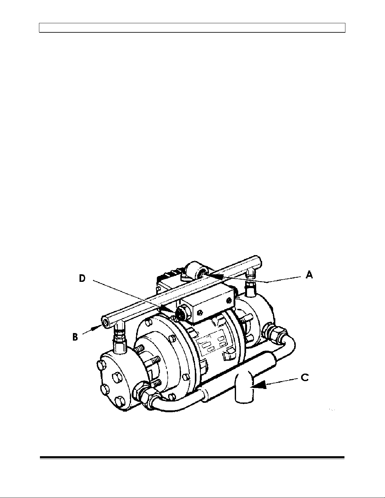
Installation Guide
Pumps should be installed in a horizontal position or optimum unctioning o
suction and delivery valves. The recommended minimum size or the suction line is
½” bore, or the pressure line is 3/8” bore and or the airline is ½” bore. It is also
recommended that pumps should be used with a hydraulic directional control
valve. The ollowing standard conditions are advised:
•Hydraulic oil having viscosity o 150 to 250 SSU
•Oil temperature 32º F to 150º F
•Air temperature 40º F to 120º F
•Room temperature 40º F to 120º F
Obstructive icing o the silencer may occur under certain temperature/humidity
conditions. This can be remedied by the addition o anti reeze oil or pneumatic
equipment to a mist lubricator.
Compressed Air ystem
It is strongly recommended that an air ilter/regulator/gauge unit having minimum
low capacity o 50 sc m is itted in order to ensure the pump has su icient air
energy to work correctly and provide the hydraulic per ormance you expect.
Hydraulic ystem
Valves, pipes, hoses and accessories should all correspond to maximum working
pressure o the pump used and be o a size that will ul ill low requirements. Bear in
mind the minimum o ½” bore or the suction line.
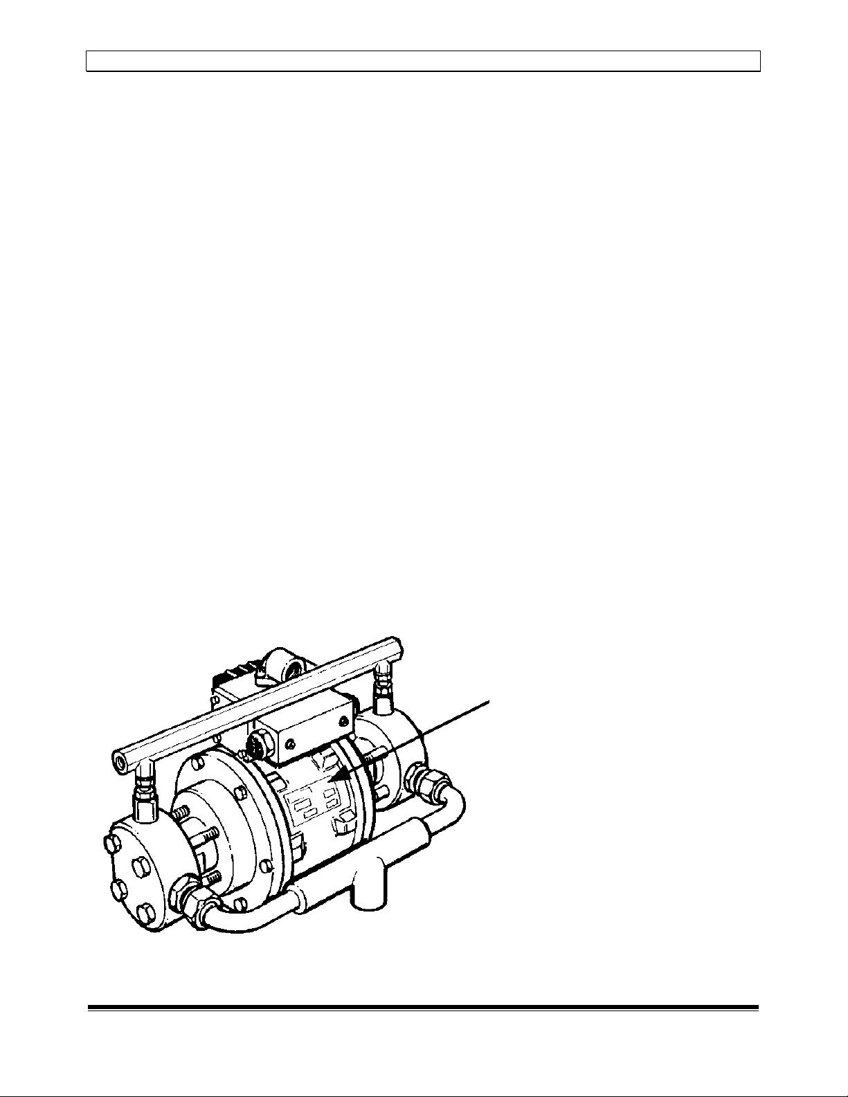
Application
Hydronic air driven hydraulic pumps are designed or operating oil hydraulic
circuits and to cover the widest range o requirements to the best advantage.
The pump itsel operates quite simply, using a known pressure intensi ication
principle. A piston with a large sur ace area is actuated by compressed air.
Attached to it is a piston with a smaller sur ace area and driven in a hydraulic
chamber generating a high level o hydraulic pressure. The continuous pumping
action is produced by the compressed air being switched by a special valve
assembly and timing mechanism. By regulating the compressed air supply pressure
rom 30 psi to 100 psi, the maximum hydraulic pressure can be adjusted by the
ratio o the pump used. As the hydraulic load o the circuit increases and the oil
pressure rises, the pump will slow down and eventually stop. In this way, the
maximum load o the circuit will be maintained without air consumption.