Hydronic Air Driven Pumps & Intensifiers 820 Installation, Use and Maintenance Booklet 1-4-2021
Page 7
tarting - Up
Oil pressure can be determined by regulation o the compressed air, bearing in mind
multiplication ratio pre-selected or the pump itsel .
The models are: P820 RATIO 1:5
P820 RATIO 1:10
P820 RATIO 1:20
P820 RATIO 1:30
P820 RATIO 1:40
For instance, when supplied with compressed air at 80 psi, the P820-5 will produce oil
pressure o 80 x ratio, 400 psi. It should be remembered that actual e iciency produced
by the pump is slightly less than given by the above theoretical calculation. This
di erence will not be noticed by a hydraulic gauge.
Having connected the compressed air supply at a low pressure, allow the pump to
operate slowly until primed and oil comes through to the oil output port. Now shut o
the air supply to the pump and securely connect the hydraulic circuit. Switch on the air
supply again and allow the pump to run in order to bleed any air out o the hydraulic
circuit.
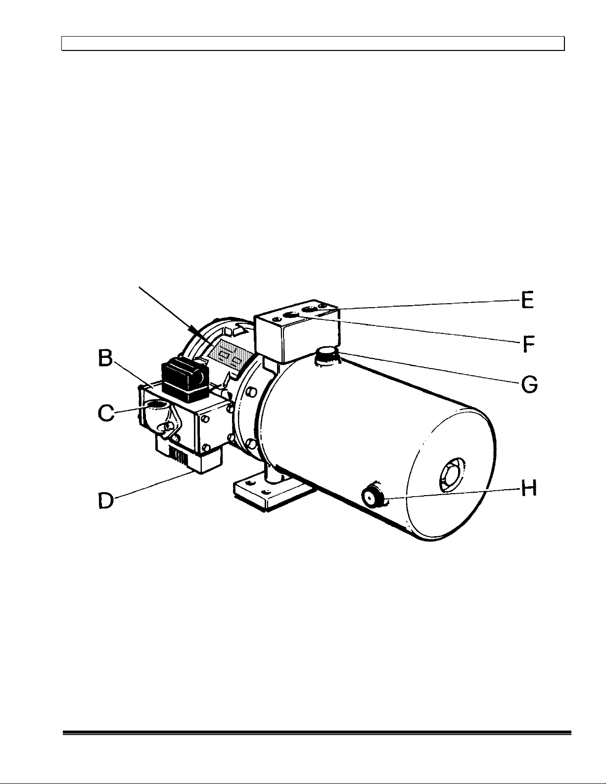
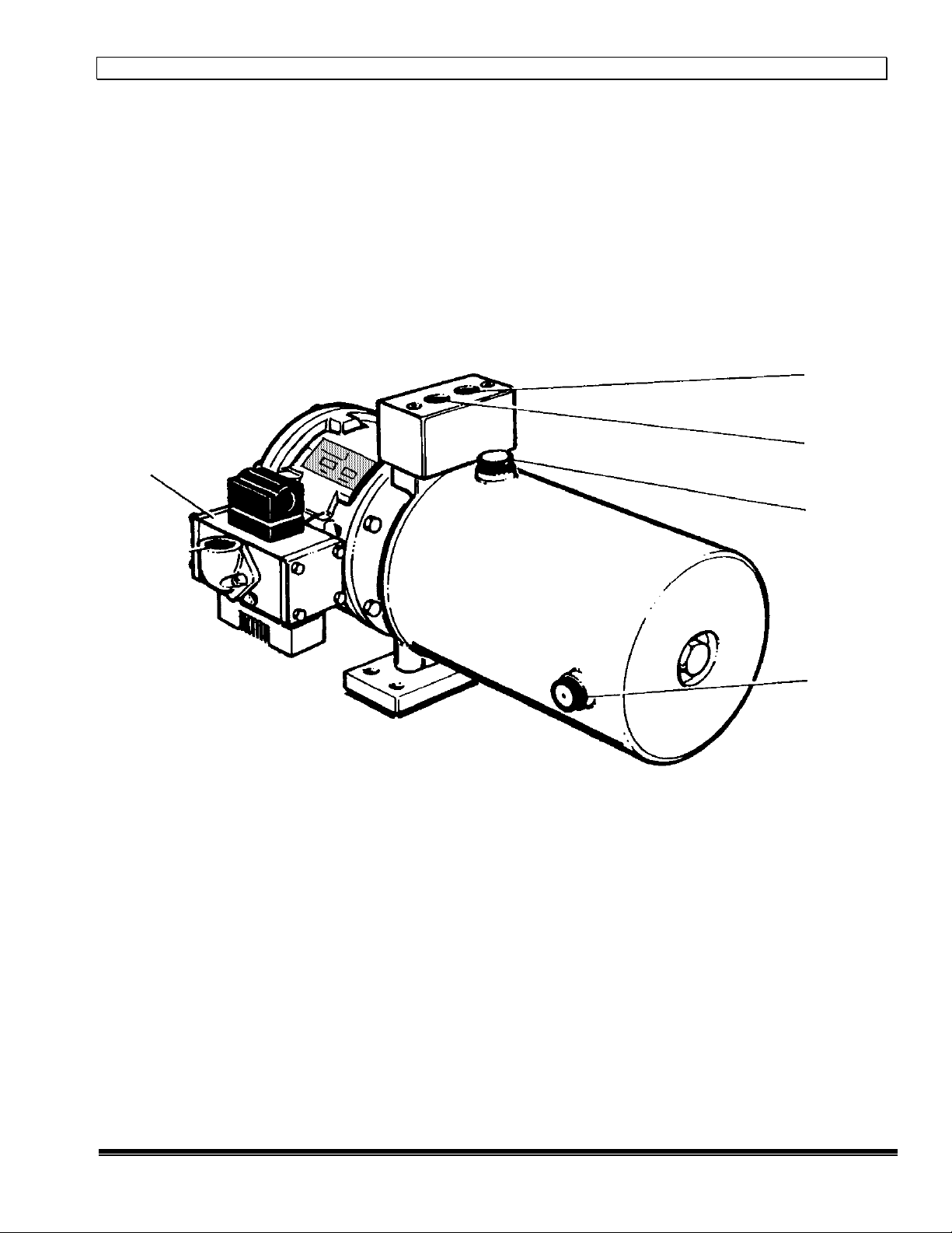
Pump eatures:
•Standard mani olds and subplates are available with various con igurations o SAE
threaded ports or output and return as well as D03 inter aces.
•Optional rotation o the 1/2” NPT air inlet elbow in our positions.
•The pump itsel works automatically and operates by way o an integral valve.
•The pneumatic drive section has graphite illed seals or minimum riction, no
lubrication requirement and long li e.
•The hydraulic section comprises an alloy steel pump casing, hard chrome plated
piston rod and bronze illed seals.
•The suction side o the pump is equipped with a spring-loaded check valve. A
spring-loaded outlet ball type check valve is incorporated in the hydraulic piston.