• Installation cont....
•3
Prior to commencing the installation you must decide which method of extraction you
wish to incorporate (these are explained
on
the following pages). If you wish to
incorporate extraction via ducting you must fit the supplied ducting connector.
You should decide whether the ducting
is
to
be
fixed to the top or rear of the extractor.
Whichever route
is
chosen a suitable aperture must
be
made
in
the rear wall or upper
cupboard to allow the ducting to pass through. The ducting connector should
be
fitted
in
position and connected to a suitable ducting kit. The remaining apertures should
be
sealed using one of the supplied aperture caps. If you wish to use the re-circulation
mode, along with a charcoal filter, both apertures should
be
sealed using the caps
provided.
Before assembling the appliance
it
is
necessary to remove the anti-grease grille.
This can be achieved by locating your fingers
in
the two aperture
on
either side and
pushing towards the rear ofthe extractor. The grille will release from thefront
and
hinge
down.To remove the grille totally hold one side steady and pull the other side towards
you
until it releases.
• Electrical Safety
Before you think about fixing, it's as well to give careful consideration to the power
connection. It
is
vital that the supply cable should
be
well shielded from your grill, hob
or oven. If it isn't, heat from any one of these sources may damagethe cable insulation
and
give rise to a fire risk. Under no circumstances should the exposed power supply
cable come within 70cm of a direct source of heat. Ideally
it
should
be
channelled into
the wall, well out of harm's way.
• For
Your
Safety
In
order to protect your appliance and minimise the risk of fire, don't barbecue food
directly under the extractor. Similarly, do not prepare flambe dishes immediately
under the extractor. If you use a gas hob, do not remove pots without first turning
offtheflame. Yourextractor
is
designedto drawgasesup and awayfrom yourhob. This
means that exposed flames may behave unpredictably
in
the vicinity of the appliance
while it
is
switched
on
. When frying take particular care to prevent the oil from catching
fire and
never
leave unattended.
• General Cleaning
Wipe the external surfaces of the extractor regularly using warm water
and
mild
detergent. Never use abrasives or wire wool since these will damage the appliance.
Always switch
off
the electricity supply prior
to
cleaning.
Alternative Methods
Of Extraction
•
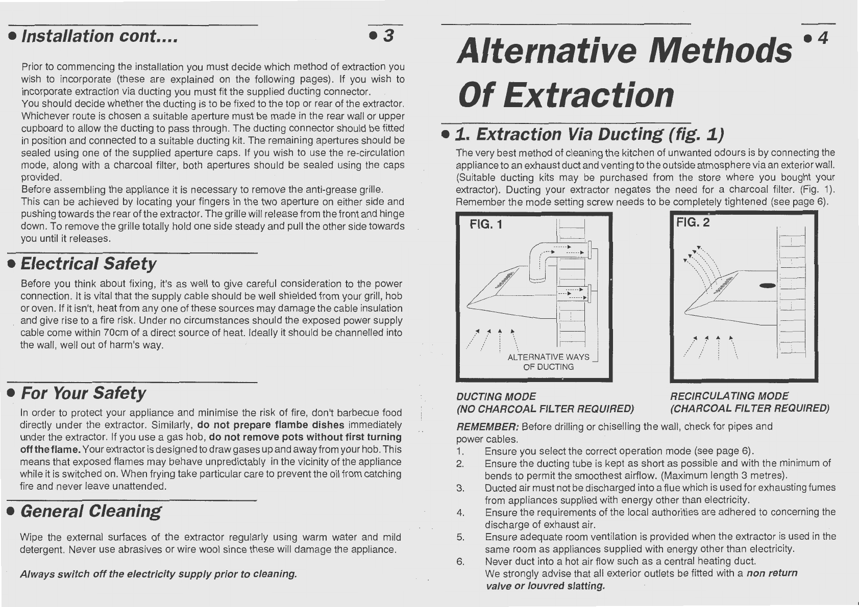
1.
Extraction
Via
Ducting (fig.
1)
•4
The very best method of cleaning the kitchen ofunwanted odours
is
by connecting the
applianceto an exhaustductand venting to theoutside atmospherevia
an
exteriorwall.
(Suitable ducting kits may
be
purchased from the store where you bought your
extractor). Ducting your extractor negates the need for a charcoal filter.
(Fig.
1).
Remember the mode setting screw needs to be completely tightened (see page
6).
FIG.1
.......
11
/ ~ \ .
.
.'
'.
ALTERNATIVE WAYS
OF DUCTING
DUCTING
MODE
(NO CHARCOAL FILTER REQUIRED)
FIG.2
Y.
:::
:\:::.-.::\,
~ : I
...
)7
~ I
1'
:"
~
~
//
_:'/
:
·.
RECIRCULATING MODE
(CHARCOAL FILTER REQUIRED)
REMEMBER: Before drilling or chiselling the wall, check for pipes and
power cables.
1.
Ensure you select the correct operation mode (see page
6)
.
2. Ensure the ducting tube
is
kept as short as possible and with the minimum of
bends to permit the smoothest airflow. (Maximum length 3 metres).
3. Ducted air mustnot
be
discharged into aflue which
is
used for exhausting fumes
from appliances supplied with energy other than electricity.
4. Ensure the requirements of the local authorities are adhered to concerning the
discharge of exhaust air.
5. Ensure adequate room ventilation
is
provided when the extractor
is
used
in
the
same room
as
appliances supplied with energy other than electricity.
6. Never duct into a hot air flow such as a central heating duct.
We strongly advise that
all
exterior outlets be fitted with a non return
valve
or
louvred slatting.