Hyundai K2F57 AC001 User manual

Genuine Accessories
Revision Date
05/11/2023 Page 1 of 13
Electronic Installation Instructions
Glasses Gloves
Mask Hearing Protection
Part Weight (Gross) FMVSS 110 Compliance Information
Technical Support
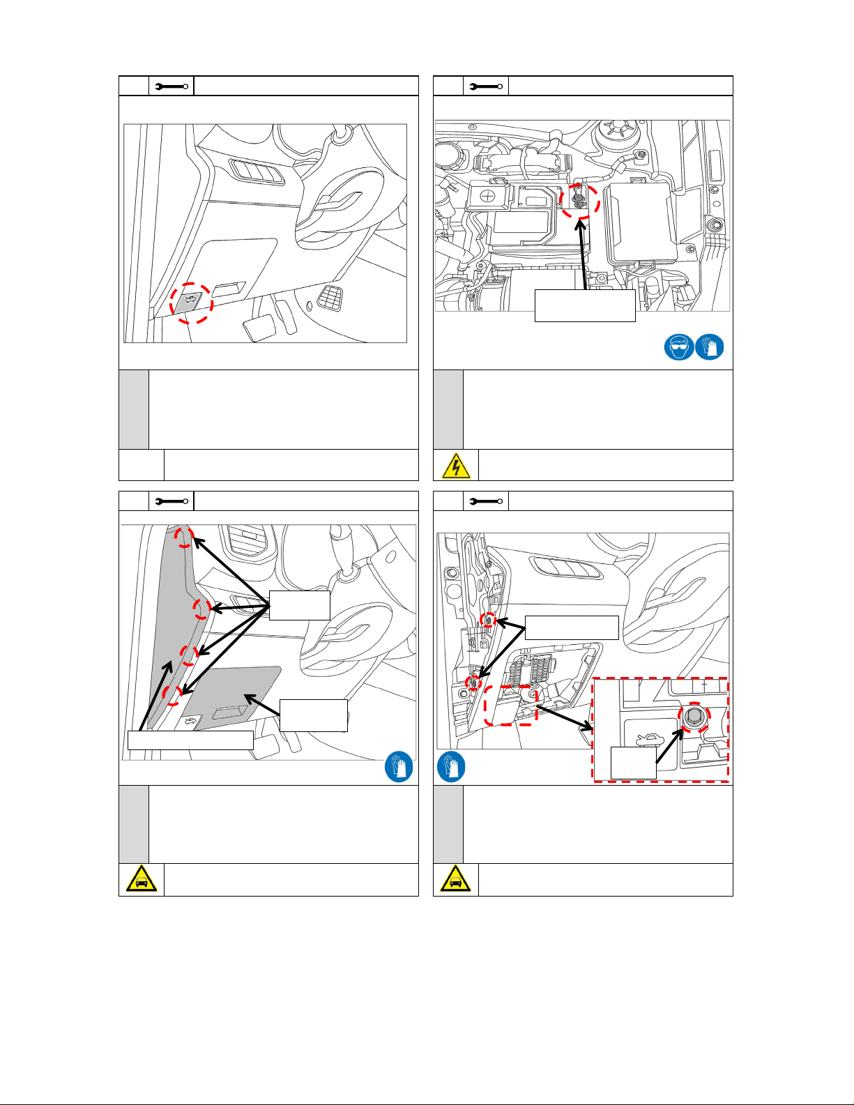
1) Read the entire Installation Instructions prior to beginning the installation of the part.
2)
3) Make sure the vehicle is completely clean and dry in the area(s) the part is to be installed.
4) Ensure the vehicle is properly protected in the area(s) that the accessory is to be installed.
5) NEVER place tools on painted surfaces, seating surfaces, dash pad, console or floor carpet/mats.
6) Always wear appropriate personal protective equipment, including gloves, safety glasses, etc., when required.
7) Record radio presets prior to disconnecting battery power, if needed.
8) Roll down the driver's window and adjust the power seats (if applicable) prior to disconnecting battery power, if needed.
9) To prevent stress on the remote start wire harness, ensure the tilt steering column is fully extended before installing the kit.
10)
Ensure Transportation Switch is switched to 'ON' on the fuse box.
11)
Vehicle should be at room temperature.
12)
If this is aprinted copy of the installation instructions, ensure you have the latest revision by
scanning the QR code or by entering the website address listed below before beginning
installation. Use the latest revision date as noted by “Rev. Date” above.
www.hyundaiaccessories.com/admin_media_uploads/installationSheets/k2f57_ac001.pdf
1.32
lbs
All dealers must determine if the Net weight they have added in the form of all options or accessories, when added to the weight of all Port/Dealer Installed
options or accessories, exceeds the lesser of 1.5% of GVWR or 100 lbs. If the additional weight does exceed the lesser of the indicated thresholds, a “Load
Carrying Capacity Reduced” label must be installed. A black, fine-point, indelible marker must be used to write by hand onto the label, the reduced carrying
capacity in kilograms or pounds, which is the total weight of all added options and accessories.
Load Label Part Number: NP070 - 09003
0.60
kg
If applicable, scan the barcode label located on the accessory part or packaging prior to installing, to register the part. If this accessory is installed as
a replacement, register the removal of the old part before registering the new part. Old and new parts will have different barcode data, and the old
registration cannot be reused.
Denotes cautions to be taken to avoid
physical injury or electronic component
damage
The order of the disassembly and reassembly steps have been optimized for maximum efficiency and the correct installation of the Remote Engine Start
kit. Disassemble vehicle components (including harness connectors) and install the kit components according to each step, as indicated. Avoid
disassembling or reassembling any components in advance to prevent unnecessary labor time and/or installation errors.
Torque Wrench Wire Cutters
Pliers
(1) 855-225-7344
M~F - 9am~5pm Pacific Standard Time
(C) Master Technician or Specialist
Authorized dealers use:
Hours:
Clip Removal Tool Trim Removal Tool Clean Cloth
50/50 Isopropyl
Alcohol (70%) and
Water Mix
N
O
T
E
Denotes important information to be
reviewed during the step
Denotes specific tools that are necessary
to complete a step
Notes to the installer:
10mm Socket Extension
Basic Required Tools
Vehicle must be equipped with mechanical key start.
Ensure vehicle does NOT have SMART KEY (PUSH BUTTON IGNITION SYSTEM).
Vehicle should be equipped with automatic transmission, power door locks, and power windows. If these features are not equipped on the vehicle, do not proceed with install.
Denotes warnings that may lead to
serious physical injury or vehicle damage
#2 Phillips
Screwdriver
(B) Dealer Technician
Instructional Symbols / Definitions
Application Notes
Denotes quality processes to be checked
prior to moving to the next step
Denotes personal protective equipment (PPEs) that
may be required for a step. Examples of safety
equipment icons noted below:
Denotes cautions to be taken to avoid
vehicle and component damage
Ratchet 12mm Socket
Language
English
5/11/2023
Rev. Date
Accessory:Vehicle Model:
Difficulty stated above reflects the minimum level of
expertise required to install the accessory:
( B )
Remote Engine Start - Key Start
(A) Customer
Venue
Difficulty:
Part No.
Model Year
Copy OEM Logo Here (→)
2020~2021
K2F57 AC001
Note:

Genuine Accessories
Revision Date
05/11/2023
Page 2 of 13
No. No. No.
1 6 11
2 7
3 8
4 9
510
Hardware Kit Contents
11 3
* Indicates extra components intentionally included in kit as spares.
Follow instructions for proper placement of each component.
Radio Presets - record customer preset frequencies if disconnecting battery power
Disconnecting Connectors Locking Connectors
When disconnecting connectors, grasp the connectors, not the wire. When locking connectors, listen for a click indicating they are securely locked.
1
1
Antenna Bracket
Relay Module
S/P: D5F57 AC170
S/P: K2F57 AC040
B
T-Tap (White)*
Antenna
1
Quick Reference Guide
1
Warning Label
1
1
Antenna Harness
FM5
FM2
14
FM1
S/P: K2F57 ACA10
S/P : S2F57 AC120
Kit Overview
S/P: K2F57 AC040
S/P: 1WF57 AC340
S/P: S2F57 AC230
Description
1
2
FM10
AM1
SAT1
SAT2
SAT4
AM3
SAT5
AM4
A
FM3
FM4
FM6
SAT3
Wire Tie*
Hardware Total
Special Instructions
FM7
FM8
AM2
FM9
AM5
2
1 Way Transmitter Fob
1
Owner's Guide
Customer Key Tag
Qty
Qty
Description
Qty
Description
Control Module
1
Harness
9
10
Quick Reference
Guide
Owner's Guide 11
CLICK
NO GOOD
8
7
6
5
1
2
3
4
Locking Tab

Genuine Accessories
Revision Date
05/11/2023
Page 3 of 13
T-Tap Installation Procedure
Remote Start Harness Connector Locations For Reference
Step 15
Ground Step 11
CAN Connector
(Fuse Box Right side)
Large End
Small End
Remote Start
Wire
Vehicle Wire
Remote
Start Wire
Vehicle Wire
1. Place T-Tap on Remote
Start Harness wire
2. Using pliers, close and
crimp T-Tap around
Remote Start Harness wire
3. Place T-Tap on vehicle wire
4. Using pliers, close and
crimp T-Tap around
vehicle wire
Step 12 &13
Light & Horn Connector
Step 7
Ignition Connector

Genuine Accessories
Revision Date
05/11/2023
Page 4 of 13
Trim Removal Tool
A. Remove the vehicle's Negative (-) Battery Cover and place it in a safe
location for reinstallation, if applicable.
B. Disconnect and isolate the vehicle's Negative (-) Battery Cable.
Ratchet and 12mm Socket, Extension and #2 Phillips Screwdriver
Caution: Do not damage the Lower Dash Panel.
2
3
A. Using a Ratchet, Extension and 12mm Socket, remove the one (1) 12mm
Bolt from the bottom of panel as shown.
B. Using a Phillips Screwdriver, remove the two (2) phillips screws
from the left side of panel as shown.
C. Store the removed screws and bolt in a safe location for reinstallation.
1
N
O
T
E
4
A. Open the Driver's Door Window.
B. Move the Driver's Seat to the rearmost position.
C. Record all pre-set radio stations, if applicable.
D. Pull the Hood Lever to open the Hood.
Ratchet and 10mm Socket
N
O
T
E
N
O
T
E
WARNING! Shock Hazard. Do not touch vehicle's negative
battery terminal to vehicle's positive battery terminal. Serious
physical injury or electronic component damage may occur.
N
O
T
E
Caution: Do not damage the Dash Panel, Fuse Panel Cover or Dash End
Cap. Make sure no pressure clips remain in the dash board.
A. Remove the fuse panel cover.
B. Gently pull the weatherstrip back from the dash area.
C. Using a trim removal tool, remove the driver’s side dash end cap panel
by prying outward to disengage the four (4) Pressure Clips.
D. Store the removed parts in a safe location for reinstallation.
Pressure
Clips
Fuse Panel
Cover
Dash End Cap Panel
Negative Battery
Cable
12mm
Bolt
Phillips Screws

Genuine Accessories
Revision Date
05/11/2023
Page 5 of 13
5
N
O
T
E
A. Release the Upper Steering Column Shroud using a trim removal tool.
B. Remove the three (3) Phillips Screws securing the Lower Steering Column Shroud as shown.
- Rotate the Steering Wheel as needed to access the two (2) Upper Screws.
C. Release the Tilt Adjust Lever on the Steering Wheel Column.
D. Carefully remove the Lower Steering Column Shroud to access the 6-Pin Ignition Switch Connector.
E. Adjust the Tilt Steering Wheel to the fully extended position and lock into place.
F. Store the removed screws in a safe location for reinstallation.
#2 Phillips Screwdriver and Trim Removal Tool
N
O
T
E
Caution! Do not damage the Lower Dash Panel, OBDII Connector or Electrical Connectors. Make sure no pressure clips remain in the dash board.
Trim Removal Tool
A. By hand, dislodge the Lower Dash Panel.
B. Disconnect the OBDII Connector.
C. Disconnect the Hood Release Cable by pulling back on the sheathing, slip the inner cable through the slot in the panel then pivot the cable through the lever and pull
the cable end out.
D. Disconnect any Electrical Connectors from the Lower Dash Panel, if applicable.
E. Store the removed part in a safe location for reinstallation.
6
**NOTE : To access screws, insert key and turn to the ACC position, in order to prevent steering wheel from locking.
Caution: Do not damage the Steering Column Shroud, Steering Wheel or Steering Column.
Pressure Clips
Retaining Tabs
Phillips
Screws
OBDII Connector

Genuine Accessories
Revision Date
05/11/2023
Page 6 of 13
A. Carefully pull the weatherstrip away from the side of the Driver's Kick
Panel and Front Door Step Sill area.
B. Using a Trim Removal Tool, remove the Driver’s Side Front Door Step Sill
Trim Panel by inserting the trim removal tool under the trim panel and prying
upward to release the three (3) Clips and two (2) Hooks.
C. Store the removed part in a safe location for reinstallation.
N
O
T
E
A. Using a Trim Removal Tool and Clip Removal Tool, remove the one (1)
Plastic Push Clip.
B. Store the removed part in a safe location for reinstallation.
Caution: Do not damage the Driver's Kick Panel or Driver’s Side Front
Door Step Sill Trim Panel.
Caution: Do not damage the Driver's Kick Panel.
N
O
T
E
Make sure the Remote Start Harness is routed as shown
8
N
O
T
E
Trim Removal Tool and Clip Removal Tool
A. Unplug the Factory 6-Pin Female Connector from the Ignition Switch.
B. Route the Remote Start Harness over through the Factory harness as shown above in the right image.
C. Plug the Factory 6-Pin Female Connector into the Remote Start 6-Pin Male Connector.
D. Plug the Remote Start Harness 6-Pin Female Connector into the Ignition Switch connector.
Trim Removal Tool 9
7
Factory 6-Pin Female
Ignition Connector
Factory 6-Pin
Female Ignition
Connector
Remote Start 6-Pin
Ignition Connectors
Hooks
Clips
Plastic Push Clip Rear Anchor Stud

Genuine Accessories
Revision Date
05/11/2023
Page 7 of 13
N
O
T
E
A. Make sure the steering column is fully extended / tilted up and locked in place before installing the three (3) wire ties.
B. Make sure the Remote Start Harness is routed as shown.
C. Using three (3) Wire Ties, secure the Remote Start Harness to the Factory Harness as shown.
D. Trim excess Wire Ties material.
Wire Cutters10
Caution: Do not damage the Steering Wheel, Steering Column, Wire Harness, or Electrical Connectors.
Move the Steering Column through it's full range of motion to ensure that Remote Start Harness and Factory Harness does not interfere with vehicle components or
make contact with sharp edges of steering column. Make sure the Remote Start Harness and Factory Harness do not contact any sharp metal parts in the steering
column, including the tilt mechanism and springs. Readjust the ties/harnesses if necessary to prevent contact.
Remote Start 6-Pin
Male Connector
Remote Start
6-Pin Female
Ignition Connector
Remote Start
Harness
Ignition Switch
Connector
Wire Ties
Factory Harnesses
Factory 6-Pin Female
Ignition Connector

Genuine Accessories
Revision Date
05/11/2023
Page 8 of 13
Wire Cutters
N
O
T
E
A. Using a Ratchet, Extension and 10mm Socket, remove the two (2) 10mm nuts from the fuse box.
B. Store the two (2) 10mm Nuts in a safe location for reinstallation.
C. Slightly pull the fuse box forward to access the rear.
D. Locate the 20-Pin female connector (Green), found on the fuse box right side as shown above.
E. Using Pliers, crimp the small end of the T-Tap onto the Red Wire of Remote Start Harness and repeat procedure for Blue Wire of Remote Start Harness
F. Match the T-Taped Red Wire of Remote Start Harness to Red Wire (Pin #19) of Vehicle 20-Pin CAN Connector and using pliers, crimp the large end of the T-Tap onto
Red Wire (Pin #19) of Vehicle 20-Pin CAN Connector. - Refer to the T-Tap Installation Procedure on page 3.
G. Match the T-Taped Blue Wire of Remote Start Harness to Blue Wire (Pin #9) of Vehicle 32-Pin CAN Connector and using pliers, crimp the large end of the T-Tap onto
Blue Wire (Pin #9) of Vehicle 20-Pin CAN Connector. - Refer to the T-Tap Installation Procedure on page 3.
Make sure to check the Correct wire Pin location for both T-Tap installations.
Connect T-Tap into Any wire if there are two wires in 1(one) Pin.
11
13
Caution : Do not pinch the factory harness & Remote Start T-Harness
between the fuse box and steel tubing.
N
O
T
E
A. Locate the two (2) connectors on the driver's kick panel area as shown
above.
B. Identify and disconnect the UPPER factory 68-pin Female Light & Horn
Connector. N
O
T
E
A. Plug the corresponding Remote Start T-Harness connectors into the factory
module and the factory 68-pin connector.
B. Using one (1) Wire Tie, secure the T-Harness to Factory Harness as shown.
Ratchet, Extension, 10mm Socket, Pliers
12
10mm Nuts
68-Pin Female
Light & Horn Connector
20-pin CAN
Connector
(Green)
Remote Start Blue Wire
T-Tap
Vehicle Blue Wire
Pin #9 (CAN-L)
Vehicle Red Wire
Pin #19 (CAN-H)
Remote Start Red Wire
Wire Tie
Factory
Harness
WIRE SIDE VIEW

Genuine Accessories
Revision Date
05/11/2023
Page 9 of 13
N
O
T
E
A. Remove the 12mm Dash Bolt from the bracket located by the Fuse Box,
as shown.
B. Route the Ground Wire across the front of the Fuse Box, as shown
above, then up and over to the 12mm Bolt hole.
C. Insert the 12mm Bolt into the Ground Wire Ring Terminal, then reinstall Bolt.
D. Torque the 12mm Bolt to:
16.7 ~ 21.6 N.m (1.7 ~ 2.2 kgf.m, 12.3 ~ 15.9 lb-ft)
A. Route the Remote Start Harness (CAN T-Taps) towards the left side of
the fuse box.
B. Reinstall the fuse box with the two (2) 10mm nuts.
C. Torque the two (2) 10mm nuts to: 10.0 N.m (1.0 kgf.m, 90 lb-in)
N
O
T
E
14 Ratchet, Torque Wrench, Extension and 10mm Socket 15 Ratchet, Torque Wrench, Extension and 12mm Socket
A. Connect the 20-Pin Connector (black) to the Control Module.
B. Connect the 4-Pin Connector (black) to the Control Module.
C. Verify the following:
- Control Module is attached to Antenna Bracket.
- Both black 6-Pin connectors are attached to Antenna and Control Module.
D. Connect 9-pin connector (White connector) to the Relay Module.
N
O
T
E
A. Using one (1) Wire Tie, secure the Relay Module to Remote Start
Harness as shown.
B. Trim excess Wire Tie material.
Ensure that each Connector is fully seated in the Control Module, in the
Antenna and in the Relay.
N
O
T
E
16 17 Wire Cutters
Caution : Do not pinch the factory harness & Remote Start Harness
between the fuse box and steel tubing.
12mm
Dash
Bolt
10mm Nuts
Black 6-Pin
Connector
Black 4-Pin
Connector
Black 20-Pin
Connector
Antenna
Control Module
Antenna
Bracket
Relay
White 9-Pin
Connector
Wire Tie

Genuine Accessories
Revision Date
05/11/2023
Page 10 of 13
21 Ratchet, 10mm Socket, Extension and Torque Wrench
A. Using one (1) Wire Tie, secure the Remote Start Harness to Vehicle
Harnesses as shown.
B. Trim excess Wire Tie material.
N
O
T
E
Wire Cutters
N
O
T
E
A. Clean the left top surface of the Radiator Cover.
- Ensure the surface is completely dry.
B. Remove the Adhesive Liner from the Warning Label, then adhere
the label to the Radiator Cover as shown. N
O
T
E
A. Reconnect the Negative (-) Battery Cable. Torque to:
5.0~ 6.0 N.m ( 0.5~0.6 kgf.m,45~ 52 lb-in)
B. Reinstall the vehicle's Negative (-) Battery Cover, if applicable.
C. Temporarily re-install the Lower Dash Panel (with the Hood Release Lever)
D. Reinstall the weatherstrip at dash area to allow Driver's Door to
close properly.
E. Close the Hood, Tailgate and all Doors.
F. Test the LOCK / UNLOCK function using Factory Key Fob.
Ensure the surface is completely dry before installing the Warning Label.
Ensure the label is aligned straight with the edge of the Radiator Cover
and without air bubbles under the label.
NOTE: If vehicle is not responding, carefully re-check all wiring
connections. If the vehicle is still not responding, follow the
Troubleshooting at the end of the instructions.
Ensure the Control Module Assembly is fully seated on the Factory
Harness.
Wire Cutters
18 19
N
O
T
E
A. Position the Control Module Assembly (Control Module + Antenna +
Antenna Harness + Antenna Bracket) as shown.
B. Using two (2) Wire Ties, secure the Control Module Assembly to Factory
Harness as shown.
C. Secure the Remote Start Harness (CAN T-Taps) to the Factory Harness
as shown using one (1) Wire Tie.
D. Trim excess Wire Tie material.
20
Wire Tie Mounting Holes
Feed wire tie through each
hole on Control Module and
tie to vehicle harness.
Wire Ties
Control Module
Assembly
Wire Tie
Wire Tie
Vehicle
Harness
Warning Label Negative Battery
Cable
Fuse Box
Relay Module

Genuine Accessories
Revision Date
05/11/2023
Page 11 of 13
23
N
O
T
E
A. Reinstall all removed parts in reverse order of disassembly.
-> Driver's Kick Panel -> Driver’s Side Front Door Step Sill Trim Panel
-> Lower Steering Column Shroud -> Upper Steering Column Shroud
-> Lower Dash Panel -> Dash End Cap Panel - > Fuse Panel Cover
-> Weatherstrip
NOTE: When reinstalling the Lower Dash Panel, torque the one (1)
12mm bolt to: 10.0 N.m (1.0 kgf.m, 90 lb-in)
B. Attach one (1) of the two (2) provided customer key tags to each
Remote Start Key Fob Rings.
C. Attach the Remote Start Fobs to each of the Factory Key Fob Rings.
D. Place the Quick Reference Guide and the Owner’s Guide into the Glove
Box.
N
O
T
E
22
GO TO →Function Check
A. Perform the Function Check at the end of the Instructions.
A. Open driver's door.
B. Insert the Key into the ignition.
Turn the key from OFF to ON position five (5) times within 5 seconds
C. After step 2 within 5 seconds.
Press button on the 1st Remote Start Fob one time.
D. After registering the 1st Remote Start Fob, within another 5 seconds,
Press button on the 2nd Remote Start Fob one time.
E. Verify that both Fobs are functioning correctly by performing lock/unlock
function.
N
O
T
E
A
Note: The remote start key Fobs come paired to the system from the
factory, and should not require re-pairing.
Note: The remote engine start system can recognize up to three (3) remotes
Fobs; the kit includes two (2) remote Fobs.
If a new Fob, or additional Fob is needed later, the Fob pairing process should
be done with the original Fob or oldest available Fob.
Remote Start Transmitter Fob Pairing Procedure
(not necessary for new installations - only needed if a fob is replaced)
#2 Phillips Screwdriver, Ratchet, 12mm Socket, Extension and
Torque Wrench
Key Tag
Key 5X
Remote Start Fob

Genuine Accessories
Revision Date
05/11/2023
Page 12 of 13
The horn does not sound even though hood is open when engine has been
started remotely.
Verify the Relay Module is correctly installed.
(Please refer to Step 16)
The vehicle lights are not blinking 2 (two) times after engine has been remotely
started.
Verify the Relay Module is correctly installed.
(Please refer to Step 16)
1. Open trunk(or tailgate).
2. Try to engine remote starter. The horn will sound five (5) time.
The vehicle LOCKS, UNLOCKS, but does not START and there is CRANKING
sound from the engine.
The LED icon lights on the Transmitter Fob does not light up.
Engine does not turn off immediately when the brake pedal is pressed
after starting engine with remote.
Result
The engine will stop.
1. Press button one time.
2. Within 3 seconds, press and hold button for 2 seconds.
1. Press button 2 times.
2. Press button 2 more times.
1. Press button one time.
(All doors, hood & trunk are closed).
Verify Driving OFF Mode after remote starting. Engine does not turn off after
Driving Off Mode even when the brake pedal is pressed.
The Transmitter Fob is not paired to the Control Module.
Follow the Remote Start Fob Pairing Procedure in the
Installation Instructions.
While the vehicle is running via remote start,
1. Open any door.
The vehicle does not LOCK by using the Remote Start Key Fob.
Ensure the Valet Mode is OFF.
(Refer to Owner's Guide for details.)
Ensure that the buttons are properly activated.
Buttons may not recognize a command if the LED icon light is
flashing.
The installation might be faulty.
Call Technical Support on Page 1.
The engine will stop after approximately fifty (50) seconds.
Check the vehicle status
1. Engine is OFF.
2. Accessory function is OFF.
3. All doors are closed.
4. Hood and tailgate are closed.
Item to be Checked
While the vehicle is running via remote start,
1. Open trunk(or tailgate).
The Engine turns off when entering the vehicle, while running under Remote
Start mode.
Troubleshooting
While the vehicle is running via remote start,
1. Open the hood.
Transmitter Fob LOCK icon will flash, vehicle signal lights will flash, and all
doors will LOCK.
Transmitter Fob KEY icon will flash, and the engine will stop.
Items to be Checked
The engine will shut down immediately.
Transmitter Fob UNLOCK icon flash, vehicle signal light flashes twice
and Driver's door will UNLOCK.
Transmitter Fob UNLOCK icon flash, vehicle signal light flashes twice
and All doors will UNLOCK.
Transmitter Fob LOCK icon will flash, vehicle signal lights will flash, and all
doors will LOCK.
Vehicle will shut off automatically after thirty (30) seconds, if key is not
in IGN ON position, as noted in the Owner's Guide in the "Driving Off"
section.
Verify the key is in the ignition ON position within 30 seconds after opening the
doors.
Verify the brake pedal is pressed after the key is in ignition ON position.
Transmitter Fob LOCK icon will flash, vehicle signal lights will flash, and all
doors will LOCK.
Transmitter Fob KEY icon will flash, the engine will crank and start, the vehicle
signal lights will flash.
Transmitter Fob UNLOCK icon will flash, vehicle signal lights will flash, and
Driver's door will UNLOCK.
Transmitter Fob UNLOCK icon will flash, vehicle signal lights will flash, and all
doors will UNLOCK.
While the vehicle is running via remote start,
1. Press button one (1) time.
While the vehicle is running via remote start,
1. Press brake pedal.
Check that the vehicle battery is not dead.
The installation might be faulty.
Call Technical Support on Page 1.
The Transmitter Fob batteries are dead.
Refer to the Owner's Guide for instructions to change the batteries.
The vehicle LOCKS, UNLOCKS, but does not START (no cranking sound).
The engine will stop after approximately thirty (30) seconds.
The remote does NOT LOCK / UNLOCK and does not START the vehicle. The
Remote LED lights flash when buttons are pressed.
Issue / Concern
While the vehicle is running via remote start,
1. Press button two (2) times.
2. Press button two (2) additional times.
While the vehicle is running via remote start,
1. Press and hold button for two (2) seconds.
Function Check

Genuine Accessories
Revision Date
05/11/2023
Page 13 of 13
Wiring Diagram
Table of contents
Other Hyundai Remote Starter manuals
Popular Remote Starter manuals by other brands

Selecta
Selecta JS012 instruction manual

Viper
Viper 791 XV installation guide

Fortin
Fortin EVO ONE Guide

CrimeStopper
CrimeStopper CoolStart RS900ER installation instructions

Linear
Linear WEATHER RESISTANT KEYLESS ENTRY SYSTEM AK-2W Installation and programming instructions

Directed Electronics
Directed Electronics CLIFFORD 1.3X owner's guide