manuals.online logo
Brands
  1. Home
  2. •
  3. Brands
  4. •
  5. I-Sotec
  6. •
  7. Car Amplifier
  8. •
  9. I-Sotec Auxgate STEREO MK 2 User manual

I-Sotec Auxgate STEREO MK 2 User manual

Auxgate®STEREO MK 2
Herzlichen Glückwunsch zum Kauf dieses ausgereiften
und innovativen Produktes .Nutzen Sie die gesammelte
Erfahrung unserer Ingenieure, Redakteure der
Fachzeitschriften und auch Car-Audio-Händler, durch die wir viele Anregungen
bekommen und umgesetzt haben.
Das Auxgate® STEREO MK2 ist eine Car-Audio-Erweiterung, die speziell für den
Einsatz in Fahrzeugen mit werksseitig eingebautem (OEM) Autoradio konzipiert
wurde. Eine Adapterlinie ermöglicht den Anschlussn in mehr als 500 Fahrzeugtypen- ohne
großen Einbau-Aufwand. Selbstverständlich kann das STEREO MK2 auch mit jedem handels-
üblichen Autoradio betrieben werden.
Bitte lesen Sie vor der Installation und Inbetriebnahme diese Anleitung sorgfältig durch, um
Bedienungsfehler zu vermeiden. Im Zweifelsfallkontaktierenn Sie bitte Ihren Fachhändler.
BESTIMMUNGSGEMÄßER GEBRAUCH
Das Auxgate® ist ausschließlich für den Betrieb im Fahrzeug am
12V Kfz-Bordnetz und am Original-Lautsprecher-Kabelbaum sowie
mit original i-sotec Adapterkabeln vorgesehen. Andere Adapterkabel
können das Auxgate® beschädigen.
A INSTALLATION
Achten Sie bei der Installation unbedingt auf eine gute Belüftung
des Gerätes. Es darf nicht abgedeckt oder in der Nähe anderer
Wärme abstrahlender Gegenstände montiertwerden. Direkte
Sonneneinstrahlung ist zu vermeiden.
Aus Sicherheitsgründen muss das Gerät fest im Fahrzeug installiert
werden. Wir empfehlen, das STEREO MK2 z.B. mit Klettband oder
Kabelbindern an einem geeigneten Untergrund zu befestigen.
Lieferumfang
Das Auxgate® STEREO MK2 wird mit folgendem Zubehör geliefert:
1. Steuereinheit 2. Betriebsanleitung
3. Iso-Stromadapter 4. i-sotec Kabelbaum
5.AUX-Anschlusskabel
A.1. ANSCHLUSS
Das Auxgate® STEREO MK2 wird mittels original i-sotec Kabelsatzr am Fahrzeug-Kabelbaum
und dem Originalradio verbunden. Bei Fahrzeugtypen ohne ISO Anschluss wird hierfür zusätz-
lich ein fahrzeugspezifischer Adapter benötigt. Überprüfen Sie bitte anhand der i-sotec
Fahrzeugliste, ob Sie zum Anschluss des STEREO MK2 an Ihrem Fahrzeug einen zusätzlichen
Adapter benötigen. Sie können dies auch online unter http://www.i-sotec.com feststellen.
A1.1 Ist-Situation
Entfernen Sie das Originalradio gemäß der Anleitung des Fahrzeugherstellers aus dem
Radioschacht, damit Sie die rückseitigen Anschlüsse des Radios erreichen können. Wenn Ihr
Originalradio einen ISO Anschluss hat, finden Sie – ggfs. neben anderen Anschlüssen wie z.B.
dem Antennenkabel - folgende zwei Stecker, die sich nach Zusammendrücken der seitlichen
Verriegelung vom Radio entfernen lassen:
ISO-Stecker für den Lautsprecheranschluss (Bild 1)
Dieser Stecker (im Folgenden als ISO-Lautsprecherstecker bezeichnet) ist
daran zu erkennen, dass die Verriegelung mittig an der schmalen Seite
des Steckers angeordnet ist. Abgesehen davon ist der Stecker meistens
aus braunem Kunststoff und die anschließenden Lautsprecherkabel sind
üblicherweise grau und weiß. Die Farbkodierungen werden allerdings
nicht einheitlich bei allen Fahrzeugherstellern eingehalten und können variieren.
ISO-Stecker für den Stromanschluss (Bild 2)
Dieser Stecker (im Folgenden als ISO-Stromstecker bezeichnet) ist eindeutig daran zu
erkennen, dass die Verriegelung nicht mittig an der schmalen Seite des Steckers
angeordnet ist. Der Stecker ist meistens aus schwarzem Kunststoff. An diesen
Stecker befinden sich üblicherweise ein rotes, ein schwarzes, ein gelbesund ggf.
weitere farbige Kabel.Die Gegenstücke zu den ISO-Steckern sind die ISO-
Kupplungen (Bild 3). Die ISO-Kupplung für den Lautsprecheranschluss
(ISO-Lautsprecher-kupplung) lässt sich nur mit den passenden ISO-
Lautsprechersteckern verbinden. Die entsprechende Nut- mittig an der
schmalen Seite der Kupplung- stellt dies sicher. Die ISO-Kupplung für den
Strom-anschluss (ISO-Stromkupplung) lässt sich ebenfalls nur mit dem pas-
senden ISO-Stromsteckern verbinden. Auch hier stellt dies eine entspre-
chende Nut seitlich an der schmalen Seite der Kupplung sicher. Bei den meisten Radios sind
diese Kupplungen direkt im Gehäuse integriert.
Um die vorhandenen ISO-Stecker, die sich am Kabelbaum des
Fahrzeugs befinden, mit dem STEREO MK2 zu verbinden, werden die
beiden hier abgebildeten ISO-Kupplungen am Kabelbaum verwendet:
ISO-Lautsprecherkupplung am Auxgate Kabelbaum (Bild
4) und ISO-Stromkupplung am Auxgate Stromadapter
(Bild 5)
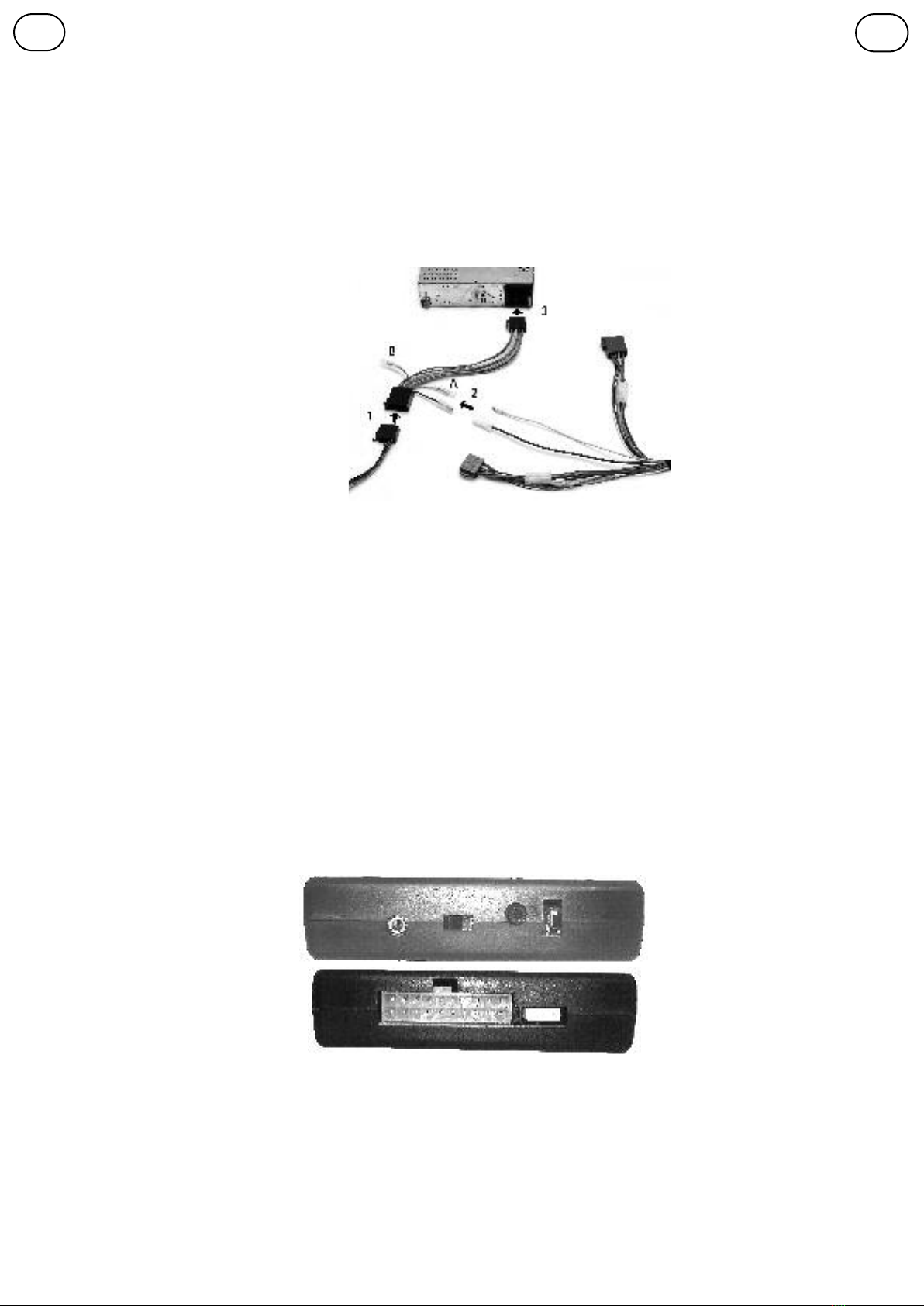
A.1.2 Überblick: Anschlussprinzip
Folgende Schritte sind notwendig, um das Auxgate®STEREO MK2 an
Ihrem vorhandenen Autoradio anzuschließen:
1. i-sotec-Kabelbaum mit dem Kompaktstecker am Auxgate® EASY ste-
reo anschließen.
2. Stromstecker am i-sotec-Kabelbaum mit der Kupplung des mitgeliefer-
ten Stromadapters verbinden.
3. ISO-Lautsprechestecker des Fahrzeug-Kabelbaums vom Radio lösen
und mit der ISO-Lautsprecherkupplung (braun) desi-sotec Kabelbaums
verbinden.
4. Die ISO-Stromstecker des Fahrzeug-Kabelbaums vom Autoradio lösen
und mit der ISO-Stromkupplung (schwarz) des mitgelieferten
Stromadapters verbinden (Details zum Stromanschluss s. Kapitel A.1.3)
5. Den ISO-Stromstecker (schwarz) des mitgelieferten Stromadapters mit
der ISO-Stromkupplung des Autoradios verbinden.
6. Den ISO-Lautsprecherstecker (braun) der Kabelbaums mit der ISO-
Lautsprecherkupplung des Autoradios verbinden.
Auxgate®STEREO MK 2
Congratulations on your purchase of this
product, and thank you for your trust! You
have acquired a technologically fully developed
and innovative product that will give you many years of outstanding music enjoyment. i-sotec
products contain the sum of experience gained over many years by our engineers, editors of spe-
cialist publications and not least the car audio dealers who have given us many ideas.
The Auxgate®STEREO MK2 is specifically designed for use in cars with integral (OEM) car radios. A
complete adaptor range permits connections without elaborate cabling work to more than 500
vehicle models. The Auxgate® can, of course, also be operated with any standard commercial car
radio.
Please read these instructions carefully before installation and operation to avoid operating prob-
lems. If in doubt, please consult your specialist dealer.
INTENDED USE
The Auxgate® is exclusively intended for operation in a car
with a 12V electrical system and the original loudspeaker
cable harness. Do only use i-sotec adaptors. Other adap-
tors could cause damage.
A INSTALLATION
When installing the equipment, be sure that it is well ven-
tilated. It must not be covered or mounted near heat emit-
ting objects or be subjected to direct sunlight.
For safety reasons, the device must be securely mounted in
the vehicle. We recommend to attach the device with vel-
cro tape or cable ties to a firm and suitable base!
A.1.Accessories
The Auxgate® package includes the following accessories:
1. Controll unit 2. Manual
3. Iso-power plug 4. Wiring harness
5. AUX connector cable
A.1 Connection
The Auxgate® is connected directly to the vehicle cable harness and to the original radio with an
in-series ISO adaptor. Vehicle models without an ISO connection require a vehicle-specific adap-
tor, available from i-sotec, for this purpose. Please consult the i-sotec vehicle list to check
whether you need an additional adaptor to connect the Auxgate® to your vehicle. You can do
this online as well at http://www.i-sotec.com.
A.1.1: Situation as is:
Remove the original radio from the radio slot according to the vehicle manufacturer’s instructions
so that you can get to the terminals on the rear side of the radio. If your original radio has an ISO
terminal – possibly next to other terminals such as the antenna cable - you will find the following
two plugs which can be removed after pressing together the locking mechanism on the side:
ISO plug for the loudspeaker connection(Pic. 1)
This plug (below also referred to as the ISO loudspeaker plug)
can be clearly identified by the fact that the locking mecha-
nism is located in the center of the narrow side of the
plug.Apart from that, the plug is usually made of brown plas-
tic and the connected loudspeaker cables are typically grey and
white.The color coding, however, is not uniformly maintained by all vehicle
manufacturers and can vary.
ISO plug for the power connection (Pic. 2)
This plug (below also referred to as the ISO power plug) can be clearly
identified by the fact that the locking mechanism is not located in the cen-
ter of the narrow side of the plug.Apart from that, the plug is usually made
of black plastic and typically a red, a black, a yellow and additional colored
cables are connected to this plug. The color coding, however,
is not uniformly maintained by all vehicle manufacturers and
can vary. The matching parts for these ISO plugs are called ISO
receptacles (Pic. 3).The ISO receptacle for the loudspeaker
connection (ISO loudspeaker receptacle) can only be connected
to the matching ISO loudspeaker plugs.
The ISO coupling for the power connection (ISO power receptacle) can also only be connected
to the matching ISO power plugs. Here, too, a corresponding groove located on the side of
the coupling ensures the correct connection. In most radios these
receptacles are directly recessed in the housing as Terminals.
Use the two ISO couplings on the i-sotec cable harness shown
here to connect the existing ISO plugs, located in the vehicle’s
cable harness, to the Auxgate®: ISO loudspeaker recepta-
cles on the i-sotec cable harness (Pic. 4) and ISO power
receptacle on the i-sotec power adaptor (Pic. 5).
A.1.2 Overview – The connection principle
The following steps are required to connect the Auxgate® to
your existing car radio:
1. Connect the i-sotec cable harness to the compact plug on the
Auxgate®.
2. Connect the power plug on the i-sotec cable harness to the
power receptacle of the supplied power adaptor.
3. Remove the ISO loudspeaker plug of the vehicle’s cable har-
ness from the car radio and connect it to the ISO loudspeaker
receptacle (brown) of the i-sotec cable harness.
4. Remove the vehicle cable harness ISO power plug from the car
radio and connect it to the ISO power receptacle (black) of the
supplied power adaptor (For detailsn see chapter A.1.3)
5. Connect the ISO power plug (black) of the supplied power
adaptor to the ISO power receptacle of the car radio.
6. Connect the ISO loudspeaker plug (brown) of the i-sotec cable
harness to the ISO loudspeaker receptacle of the car radio
EN
D
5
12
3
4
A.1.3 Connection to the power supply
The Auxgate® is supplied with an ISO power adaptor as standard equipment. The
power adaptor is connected between the car radio and the vehicle cable harness.
1.Remove the vehicle cable harness’ ISO power plug from the car radio and connect it to the ISO
power receptacle of the i-sotec power adaptor.
2.Connect the black and yellowg cable harness of the Auxgate® to the yellow and black ones at
the power adaptor. Other vehicle-specific adaptors can be connected to the Auxgate® with this
plug-in connection.
3.Connect the ISO power plug of the i-sotec power adaptor to the ISO power receptacle of the car
radio. Since different vehicle manufacturers switch the connections at the ISO plug for 12V positive
plus (memory, yellow) and 12V supply voltage (coupled to the ignition, red), the i-sotec power
adaptor has two alternative plug-in connectors for positive plus:
A.Standard connection for positive plus (as delivered)
B. Alternative coupling for positive plus
Incase of doubt, the correct assignment can be checked with a voltmeter or test lamp. The 1-pin
coupling (A or B) at which one measures against ground even with switched off ignition +12V cur-
rent, is to be connected to the corresponding 1-pin plug.
A.1.4 Caution notice
The fuse for the device may only be replaced with
afuse of the same rating (10A) to avoid damage
to the device. Higher rated fuses can result in
dangerous consequences!!! We reccomend to let
the fuses get changed by a qualified workshop.
A.2 TECHNICAL DATA
Output Power: 4 x 17 W
Operating voltage: 10 ,4-14,4V DC
Required power: Max. 10A
Loudspeaker impedance: Min. 4 Ohm
THD+N: <0.01%, SNR: >96dB
Max. ambient temperature:45°C
Dimensions: (LxHxW) 110 x 110 x 27 mm
24 months Limited Warranty
LIABILITY EXCLUSION
i-sotec assumes no liability for damage that is
caused by improper use of the device, improper
installation or incorrect connections or non-observance of the handling instructions described in
these operating instructions.The device may only be operated with original i-sotec
adaptor plugs and cables (for more see “Intended Use”).
A.3 TROUBLESHOOTING
1. No signal reproduction:
•Main fuse or device fuse is defective • Radio is not turned on
•Levelreduction activatet• Adaptor cable not connected properly
2. Distorted sound:
• Check the loudspeakers and their supply leads for short circuits
• Are the loudspeakers working properly?
• Total volume is set too high. Reduce the level on the radio
3. Background noises in the loudspeakers
• Poor ground connection/contact ?• Did you use several grounding points instead of a single
one?
•Signal cable installed close to other vehicle cables?
Have you been unable to solve the problem? Please ask your i-sotec dealer for support!
BOperation and Connection of the Auxgate® EASY stereo
B.1 Connection
The connection of the Auxgate®STEREO MK2 to power supply and speakers is to be done as
described in chapter A1. The AUX source is connected directly to the device with a 3.5 mm
cable via the AUX input.
B.2 Operating Elements and Connections
1: Connection “AUX”
2: Switch “4/ 2channel - LoudspeakerS front/ rear -
only front”
switch to the left: 4 channel, to the right:only 2chan-
nel
3: Volume Control
4: Connection “Remote”
5: System plug (power, loudspeaker in- and outputs)
6: Fuse (10A)
B.3 Operation
If there is a signal (e.g. navigation signal or phone
call) at the input, the radio will be muted automatical-
ly and the signal is amplified.Relatet to the switch
4/2 CH, the signal either comes throu front and rear
or throu the front loudspeakers. The volume is controlled at each connected source with their
integrated volume controls but can be pre-set at the Auxgate®.
B.4 Settings
The main volume of the Aux sources is to be pre-set by the level-control at the Auxgate®
device. Please set this control to 0. Connect a source (e.g. navigation system) to the AUX input
(1) and set the internal volume to 70%. Then turn the poti to desired listening volume. When
driving, the volume can be controlled at the connected source. Please avoid setting it too low
or turning it down completely, as secure signal management can only be guaranteed at a cer-
tain input level.
A1.3 Anschluss der Spannungsversorgung
Das Auxgate® STEREO MK2 wird mit einem ISO Stromadapter ausgeliefert und
zwischen Autoradio und Fahrzeug-Kabelbaum angeschlossen.
1. ISO-Stromstecker des Fahrzeugkabelbaums vom Autoradio trennen und mit der ISO-
Stromkupplung des i-sotec Stromadapters verbinden.
2. Das schwarze und gelbe Kabel am Kabelbaum mit dem jeweiligen schwarzen und gelben
Kabel am Stromadapter verbinden. An dieser Steckverbindung können ggfs. auch andere fahr-
zeugspezifische Adapter mit dem Auxgate® EASY stereo verbunden werden.
3.ISO-Stromstecker des i-sotec Stromadapters mit der ISO-Stromkupplung des Autoradios verbinden.
Da verschiedene Fahrzeughersteller die Anschlüsse für 12V Dauerplus (Memory, gelb) und 12V
Versorgungsspannung (an Zündung gekoppelt, rot) am ISO-Stecker vertauschen, besitzt der i-
sotec Stromadapter zwei alternative Steckverbindungen für Dauerplus:
A. Standardanschluss für Dauerplus gelb, (Auslieferungszustand)
B. Alternative Kupplung für Dauerplus (rot, optional)
Die korrekte Zuordnung ist im Zweifelsfall zuerst mit einem Voltmeter ode einer r Prüflampe zu
testen. Diejenige Kupplung (A oder B), an der auch bei ausgeschalteter Zündung +12V
Spannung gegen Masse gemessen wird, ist mit dem zugehörigen Stecker zu verbinden
A1.4 Warnhinweis
Die Sicherung am Gerät darf nur mit dem gleichen Wert (10A) ersetzt
werden, um eine Beschädigung des Gerätes zu verhindern. Höhere
Werte können zu gefährlichen Folgeschäden führen und den Verlust
der Garantie bewirken! Wir empfehlen, den Austausch der Sicherung in
einer Fachwerkstatt vornehmen zu lassen.
A2. Technische Daten
Ausgangsleistung: 4 x 17 W
Betriebsspannung: 10,4-14,4V DC
Strombedarf: Max. 10A, Lautsprecher Impedanz:: Min. 4 Ohm
THD+N: <0,01%, SNR: >96dB Max. Umgebungstemperatur: 45°C
Abmessungen: (LxHxB) 110x110x27 mm Gewährleistung 24 Monate
HAFTUNGSAUSSCHLUSS
i-sotec übernimmt keine Haftung für Schäden, die durch unsachgemä-
ßen Gebrauch des Gerätes, unsachgemäße Installation oder falschen
Anschluss sowie Nichtbeachtung der in dieser Bedienungsanleitung
beschriebenen Handhabungsweisen entstehen. Das Gerät darf nur
mit Original i-sotec Adaptersteckern und Kabeln betrieben werden (Weiteres siehe
„Bestimmungsgemäßer Gebrauch”).
A.3 Mögliche Fehlerquellen
1.Keine Signalwiedergabe
• Hauptsicherung oder Gerätesicherung defekt
•Radio nicht eingeschaltet
•Pegelabsenkung aktiviert • Adapterkabel nicht richtig eingesteckt
2. Verzerrter Klang:
• Prüfen Sie die Lautsprecher und deren Zuleitungen auf Kurzschlüsse.
• Sind die Lautsprecher in Ordnung?
• Gesamtlautstärke zu hoch eingestellt. Reduzieren Sie den Pegel am Radio.
3. Störgeräusche in den Lautsprechern
• Schlechter Masseanschluss/-kontakt?
• Signalkabel in Nähe anderer Fahrzeugkabel verlegt?
• Mehrere Massepunkte statt eines gemeinsamen verwendet?
Konnten Sie den Fehler nicht beheben? Ihr i-sotec Fachhändler hilft gern weiter!
BBedienung und Anschluss Auxgate®STEREO MK2
B.1 Allgemeiner Anschluss
Der Anschluss des Auxgate® STEREO MK2 an das Autoradio, die Stromversorgung und die
Lautsprecher erfolgt wie im Kapitel „Einbau“ beschrieben. Der Kopfhörer-Ausgang des
Navigationsgerätes oder einer anderen Klangquelle wird mit einem 3,5-mm-Klinkenkabel über
den Eingang “Aux”(1) direkt am Gerät angeschlossen. Falls sich das Gerät nicht einschaltet,
nutzen Sie bitte den Remote-Eingang(4) des Auxgate-Gerätes.
B.2 Bedienelemente und Anschlüsse
1: Anschluss “AUX”
2: Schalter „4 bzw. 2 Kanalwiedergabe - Lautsprecher vorne
und hinten- nur vorne”
Schalter links (wie im Bild): 4-Kanal, Schalter rechts: nur
vordere Lautsprecher aktiv
3: Lautstärke-Drehregler
4: Anschluss “Remote”
5: Systemstecker (Strom, Lautsprecher-Ein- und Ausgänge)
6: Gerätesicherung (10 A)
B.3 Betrieb
Liegt am Aux-Eingang ein Signal, etwa eine Navi-Ansage, an,
wird das Radio automatisch gemutet und dieses Signal wieder-
gegeben. Abhängig von der Schalterstellung 4/2 CH, erfolgt die
Wiedergabe entweder über alle vier oder nur über die vorderen
Lautsprecher.Die Lautstärke der AUX-Quelle wird direkt an den daran angeschlossenen Geräten gere-
gelt; am Auxgate® EASY stereo erfolgt lediglich eine Voreinstellung.
B.4 Auxgate® Einstellungen
Die Grundlautstärke der Aux-Quelle wird über den Poti-Drehregler an der Geräterückseite (3)
eingestellt. Drehen Sie diesen zur Einstellung bitte auf Null - Linksanschlag.
Schließen Sie nun die Signalquelle (z.B. Navigationsgerät) mit 60 bis 70 Prozent seiner Maximal-
Lautstärke am Eingang AUX (1) an. Stellen Sie den Drehregler am Auxgate® anschließend so ein,
dass eine angenehme Lautstärke erreicht wird. Während der Fahrt können Sie die Lautstärke direkt
am angeschlossenen Gerät verstellen. Beachten Sie dabei, dass bei zu geringer Lautstärke der Aux-
Quelle keine sichere Signalerkennung gewährleistet werden kann.
DEN
1234
56

Other I-Sotec Car Amplifier manuals

I-Sotec i-soamp-2 User manual

I-Sotec

I-Sotec i-soamp-2 User manual

I-Sotec i-soamp-2 User manual

I-Sotec

I-Sotec i-soamp-2 User manual

I-Sotec i-soamp-4 User manual

I-Sotec

I-Sotec i-soamp-4 User manual

Popular Car Amplifier manuals by other brands

Steg Qx Mos 105.4x user manual

Steg

Steg Qx Mos 105.4x user manual

Lanzar VIBE 1800D owner's manual

Lanzar

Lanzar VIBE 1800D owner's manual

Audiopipe APSM-1150 owner's manual

Audiopipe

Audiopipe APSM-1150 owner's manual

JL Audio RD400/4 owner's manual

JL Audio

JL Audio RD400/4 owner's manual

Kenwood KAC-PS4D instruction manual

Kenwood

Kenwood KAC-PS4D instruction manual

Harman Kardon CA470 user guide

Harman Kardon

Harman Kardon CA470 user guide

JL Audio J21000.1 owner's manual

JL Audio

JL Audio J21000.1 owner's manual

JBL GTO7001 Service manual

JBL

JBL GTO7001 Service manual

MTX Thunder TA High TA3404 supplementary guide

MTX

MTX Thunder TA High TA3404 supplementary guide

Pyle Elite PLA3000D user manual

Pyle

Pyle Elite PLA3000D user manual

Kicker ZX300.1 owner's manual

Kicker

Kicker ZX300.1 owner's manual

Ssl Evolution EV3000D user guide

Ssl

Ssl Evolution EV3000D user guide

Ssl Evolution EV5000D user manual

Ssl

Ssl Evolution EV5000D user manual

ARC Audio XDi owner's manual

ARC Audio

ARC Audio XDi owner's manual

Cadence CAP2DR installation manual

Cadence

Cadence CAP2DR installation manual

Lanzar Vector VCT-2110 owner's manual

Lanzar

Lanzar Vector VCT-2110 owner's manual

Celestra FA275x owner's manual

Celestra

Celestra FA275x owner's manual

Kenwood X600F - Excelon - Car Amplifier instruction manual

Kenwood

Kenwood X600F - Excelon - Car Amplifier instruction manual

manuals.online logo
manuals.online logoBrands
  • About & Mission
  • Contact us
  • Privacy Policy
  • Terms and Conditions

Copyright 2025 Manuals.Online. All Rights Reserved.