manuals.online logo
Brands
  1. Home
  2. •
  3. Brands
  4. •
  5. I-Sotec
  6. •
  7. Car Amplifier
  8. •
  9. I-Sotec i-soamp-2 User manual

I-Sotec i-soamp-2 User manual

Other manuals for i-soamp-2

1

This manual suits for next models

2

Other I-Sotec Car Amplifier manuals

I-Sotec Auxgate STEREO MK 2 User manual

I-Sotec

I-Sotec Auxgate STEREO MK 2 User manual

I-Sotec i-soamp-2 User manual

I-Sotec

I-Sotec i-soamp-2 User manual

I-Sotec i-soamp-4 User manual

I-Sotec

I-Sotec i-soamp-4 User manual

Popular Car Amplifier manuals by other brands

Boss Audio Systems US140 user manual

Boss Audio Systems

Boss Audio Systems US140 user manual

Boss Audio Systems FNX2000 user manual

Boss Audio Systems

Boss Audio Systems FNX2000 user manual

Pioneer GM-D8500M owner's manual

Pioneer

Pioneer GM-D8500M owner's manual

MTX Thunder Marine TM904 user guide

MTX

MTX Thunder Marine TM904 user guide

MTX Thunder TA Super TA92001 Connection guide

MTX

MTX Thunder TA Super TA92001 Connection guide

Lanier 480-0239 Material safety data sheet

Lanier

Lanier 480-0239 Material safety data sheet

Kenwood KAC-642 instruction manual

Kenwood

Kenwood KAC-642 instruction manual

Sony XM-405EQX Marketing Specifications Product guide

Sony

Sony XM-405EQX Marketing Specifications Product guide

Jensen XA4150 owner's manual

Jensen

Jensen XA4150 owner's manual

Audiopipe AQX-660.2 owner's manual

Audiopipe

Audiopipe AQX-660.2 owner's manual

Clarion APA2001  APA2001 APA2001 Owners & installation manual

Clarion

Clarion APA2001 APA2001 APA2001 Owners & installation manual

Cyfre CHACDMA-819 installation manual

Cyfre

Cyfre CHACDMA-819 installation manual

Sony XM-7547 Service manual

Sony

Sony XM-7547 Service manual

Alpine PDX11000 - Amplifier Review guide

Alpine

Alpine PDX11000 - Amplifier Review guide

Steg Qx Mos 105.4x user manual

Steg

Steg Qx Mos 105.4x user manual

Jensen PS1220M Installation & operation manual

Jensen

Jensen PS1220M Installation & operation manual

Kenwood KAC-8105D instruction manual

Kenwood

Kenwood KAC-8105D instruction manual

Pioneer GM-5000T owner's manual

Pioneer

Pioneer GM-5000T owner's manual

manuals.online logo
manuals.online logoBrands
  • About & Mission
  • Contact us
  • Privacy Policy
  • Terms and Conditions

Copyright 2025 Manuals.Online. All Rights Reserved.

intelligent solutions and technologies
Germany
manual
i-soamp-2 / i-soamp-4
i-soamp-4cx
Car-Audio-Amplifiers
by
i-soamp-4, i-soamp-2,
i-soamp-4cx
Congratulations on your purchase of this i-sotec product, and thank you for your
trust! With this i-sotec-amplifier you have acquired a technologically fully develo-
ped and innovative product that will give you many years of outstanding music
enjoyment.
i-sotec products contain the sum of experience gained over many years by our
engineers, editors of specialist publications and not least the car audio dealers
who have given us many ideas.
The i-soamp was specifically designed for use in cars with integral (OEM) car
radios. A complete adaptor range permits connections without elaborate cabling
work to more than 500 vehicle models. The i-soamp can, of course, also be ope-
rated with any standard commercial car radio. Alternativlye the channels may be
configured to bridge mode to enable a subwoofer to be operated with nearly
twice the output.
The many adjustment and adaptation possibilities make the i-soamp an all-round
genius for your car.
Please read these instructions carefully before installation and operation to avoid
operating problems. If in doubt, please consult your specialist dealer.
INTENDED USE:
The i-soamp is exclusively intended for operation in a car with a 12V electrical
system and the original loudspeaker cable harness. It takes the audio signals of
the OEM radio and conducts them to the vehicle loudspeakers in amplified form.
Content Of This Manual
AInstallation Guide, Troubleshooting, Technical Data
BUser’s Guide i-soamp-4
CUser’s Guide i-soamp-2
DUser’s Guide i-soamp-4cx
i-soamp-4, i-soamp-2,
i-soamp-4cx
Wir beglückwünschen Sie zum Kauf dieses i-sotec Produktes und danken für
Ihr Vertrauen! Mit diesem Car-Audio-Gerät haben Sie ein technologisch aus-
gereiftes und innovatives Produkt erworben, das Ihnen viele Jahre hervorra-
genden Musikgenuss ermöglichen wird. In i-sotec Produkten steckt die
gesammelte Erfahrung unserer Ingenieure, Redakteure der Fachzeitschriften
und nicht zuletzt auch Car-Audio-Händler, durch die wir viele Anregungen
bekommen haben.
Der i-soamp ist ein Car-Audio-Verstärker, der speziell für den Einsatz in
Fahrzeugen mit fest eingebautem (OEM) Autoradio konzipiert wurde. Eine
komplette Adapterlinie ermöglicht den Anschluss ohne aufwendige
Verkabelungsarbeiten bei mehr als 500 Fahrzeugtypen. Natürlich kann der i-
soamp auch mit jedem handelsüblichen Autoradio betrieben werden. Es
besteht außerdem die Möglichkeit, die Kanäle in Brücke zu schalten, um so
mit annähernd der doppelten Leistung Subwoofer betreiben zu können. Die
vielfältigen Einstell- und Anpassungsmöglichkeiten machen den i-soamp zum
Allround-Genie im Auto.
Bitte lesen Sie vor Installation und Inbetriebnahme diese Anleitung sorgfältig
durch, um Bedienungsfehler zu vermeiden. Im Zweifelsfall wenden Sie sich
bitte an Ihren Fachhändler.
BESTIMMUNGSGEMÄßER GEBRAUCH:
Der i-soamp ist ausschließlich für den Betrieb im Fahrzeug am 12V Kfz-
Bordnetz und am Original-Lautsprecher-Kabelbaum sowie mit Original i-sotec
Adapterkabeln und i-sotec Subwoofern (optional) vorgesehen. Andere
Adapterkabel und Subwoofer können den i-soamp beschädigen. Der i-soamp
nimmt die Audiosignale des OEM Radios auf und führt sie den
Fahrzeuglautsprechern verstärkt wieder zu
Inhalt:
AEinbauanleitung, Fehlersuche, technische Daten
B Bedienungsanleitung i-soamp-4
C Bedienungsanleitung i-soamp-2
D Bedienungsanleitung i-soamp-4cx
UK
D
AINSTALLATION
When installing the equip-
ment, be sure that it is well
ventilated. It must not be
covered or mounted near heat emit-
ting objects or be subjected to direct
sunlight.
The i-soamp can heat itself up signifi-
cantly (up to 80°C); it is therefore
important to ensure sufficient clearan-
ce from other heat-sensitive vehicle
components (particulary plastic-parts
and electronic components)!
For safety reasons, the device must be
securely mounted in the vehicle. Attach
the device with the supplied mounting
screws to a firm and suitable base. Do
not drill holes in parts of the vehicle if
you are not sure what is located
behind. Watch out for wiring harnesses
and fuel lines!!!
A.1.Accessorys
The i-soamp package includes the fol-
lowing accessorys:
1. Amplifier unit 2. Manual
3. Iso-power plug 4. Wiring harness
5. Fastening screws (4 pieces, not in
picture)
6. Remote cable (i-soamp-2 only,not in picture)
A1 Connection
The i-soamp is connected directly to the vehicle cable harness and to the original
radio with an adaptor. Vehicle models without an ISO connection require a speci-
al vehicle-specific adaptor for this purpose. Please consult the i-sotec vehicle list
to check whether you need an additional adaptor to connect the i-soamp to
your vehicle. You can do this online as well at http://www.i-sotec.com/
A INSTALLATION
Achten Sie bei der
Installation unbedingt auf
eine gute Belüftung des Gerätes.
Es darf nicht abgedeckt oder in der
Nähe anderer Wärme abstrahlen-
der Gegenstände montiert oder
direkter Sonneneinstrahlung aus-
gesetzt werden!
Der i-soamp kann sich selbst stark
erwärmen (bis zu 80°C), daher ist
auf ausreichenden Abstand zu
anderen wärmeempfindlichen
Fahrzeugteilen (insbesondere
Kunststoffteile und elektronische
Komponenten) zu achten!
Aus Sicherheitsgründen muss das
Gerät fest im Fahrzeug installiert
werden. Befestigen Sie das Gerät
mit den mitgelieferten
Montageschrauben an einem
festen und geeigneten
Untergrund. Bohren Sie keine
Löcher in Teile des Fahrzeuges,
wenn Sie nicht wissen, was sich
dahinter befindet. Achten Sie auf
Kabelbäume und Benzinleitungen!
Lieferumfang
Die i-sotec Car-Audio-Systeme werden mit folgendem Zubehör geliefert:
1. Verstärkereinheit
2. Handbuch
3. Iso-Stromadapter
4. i-sotec Kabelbaum
5. Befestigungsschrauben (4 Stück, ohne Abbildung)
6. Remote-Kabel (nur i-soamp-2, ohne Abbildung)
A1 ANSCHLUSS
Der i-soamp wird mittels original i-sotec Adapter direkt an den Fahrzeug-
Kabelbaum und an das Originalradio angeschlossen. Bei Fahrzeugtypen ohne
ISO Anschluss wird hierfür zusätzlich ein fahrzeugspezifischer Adapter benö-
tigt. Überprüfen Sie bitte anhand der i-sotec Fahrzeugliste, ob Sie zum
Anschluss des i-soamp an Ihrem Fahrzeug einen zusätzlichen Adapter benöti-
gen. Sie können dies auch online unter http://www.i-sotec.com feststellen.
DUK
A1.1: Situation as is:
Remove the original radio from the radio slot according
to the vehicle manufacturer's instructions so that you
can get to the terminals on the rear side of the radio. If
your original radio has an ISO terminal – possibly next to other ter-
minals such as the antenna cable - you will find the following two
plugs which can be removed after pressing together the locking
mechanism on the side:
ISO plug for the loudspeaker connection (Pic. 1)
This plug (below also referred to as the ISO loudspeaker plug) can
be clearly identified by the fact that the locking mechanism is loca-
ted in the center of the narrow side of the plug.
Apart from that, the plug is usually made of brown plastic and the
connected loudspeaker cables are typically grey and white.
The color coding, however, is not uniformly maintained by all vehicle
manufacturers and can vary.
ISO plug for the power connection (Pic. 2)
This plug (below also referred to as the ISO power plug) can be clearly identified
by the fact that the locking mechanism is not located in the center of
the narrow side of the plug.
Apart from that, the plug is usually made of black plastic and
typically a red, a black, a yellow and additional colored cables are
connected to this plug. The color coding, however, is not uni-
formly maintained by all vehicle manufacturers and can vary.
The mating parts for these ISO plugs are called ISO receptacles (Pic. 3).
The ISO receptacle for the loudspeaker connection (ISO loudspeaker receptacle)
can only be connected to the matching ISO loudspeaker plugs.
The ISO coupling for the power connection (ISO power receptacle)
can also only be connected to the matching ISO power plugs. Here,
too, a corresponding groove located on the side of the coupling
ensures the correct connection. In most radios these receptacles are
directly recessed in the housing as Terminals.
Use the two ISO couplings on the i-soamp cable harness shown here to connect
the existing ISO plugs, located in the vehicle's cable harness, to the
i-soamp:
ISO loudspeaker receptacles on the i-soamp cable har-
ness (Pic. 4) and ISO power receptacle on the i-soamp
power adaptor (Pic. 5).
A1.1 Ist-Situation
Entfernen Sie das Originalradio gemäß der Anleitung
des Fahrzeugherstellers aus dem Radioschacht, damit
Sie die rückseitigen Anschlüsse des Radios erreichen kön-
nen. Wenn Ihr Originalradio einen ISO Anschluss hat, finden Sie –
ggfs. neben anderen Anschlüssen wie z.B. dem Antennenkabel -
folgende zwei Stecker, die sich nach Zusammendrücken der seitli-
chen Verriegelung vom Radio entfernen lassen:
ISO-Stecker für den Lautsprecheranschluss (Bild 1)
Dieser Stecker (im Folgenden als ISO-Lautsprecherstecker bezeich-
net) ist daran zu erkennen, dass die Verriegelung mittig an der
schmalen Seite des Steckers angeordnet ist. Abgesehen davon ist
der Stecker meistens aus braunem Kunststoff und die anschlie-
ßenden Lautsprecherkabel sind üblicherweise grau und weiß. Die
Farbkodierungen werden allerdings nicht einheitlich bei allen
Fahrzeugherstellern eingehalten und können variieren.
ISO-Stecker für den Stromanschluss (Bild 2)
Dieser Stecker (im Folgenden als ISO-Stromstecker bezeichnet) ist eindeutig
daran zu erkennen, dass die Verriegelung nicht mittig an der schmalen Seite
des Steckers angeordnet ist. Der Stecker ist meistens aus schwar-
zem Kunststoff. An diesen Stecker schließen üblicherweise ein
rotes, ein schwarzes, ein gelbes sowie weitere farbige Kabel an.
Die Gegenstücke zu den ISO-Steckern sind die ISO-
Kupplungen (Bild 3). Die ISO-Kupplung für den
Lautsprecheranschluss (ISO-Lautsprecherkupplung) lässt sich nur
mit den passenden ISO-Lautsprechersteckern verbinden. Die ent-
sprechende Nut mittig an der schmalen Seite der Kupplung stellt dies sicher.
Die ISO-Kupplung für den Stromanschluss (ISO-Stromkupplung) lässt sich
ebenfalls nur mit den passenden ISO-Stromsteckern verbinden. Auch hier stellt
eine entsprechende Nut seitlich an der schmalen Seite der
Kupplung dies sicher. Bei den meisten Radios sind diese
Kupplungen direkt im Gehäuse als „Steckdosen“ integriert.
Um die vorhandenen ISO-Stecker, die sich am Kabelbaum des
Fahrzeugs befinden mit dem i-soamp zu verbinden, werden die
beiden hier abgebildeten ISO-Kupplungen am i-soamp
Kabelbaum verwendet:
ISO-Lautsprecherkupplung am i-soamp Kabelbaum
(Bild 4)
ISO-Stromkupplung am i-soamp Stromadapter (Bild 5)
4
5
1
3
2
DUK
A1.2 Overview – The i-soamp connection principle
This depiction is designed to give you an overview of how the
i-soamp is connected to your vehicle's components in principle.
The following steps are required to connect the i-soamp to your existing car
radio:
1. Connect the i-soamp cable harness to the compact plug on the i-soamp.
2. Connect the power plug on
the i-soamp cable harness to the
power receptacle of the supplied
power adaptor.
3. Remove the ISO loudspeaker
receptacle of the vehicle's cable
harness from the car radio and
connect it to the ISO loudspea-
ker coupling (brown) of the
i-soamp cable harness. (For
details on connection variants
see Chapter A1.3,A1.4 and
A1.5)
4. Remove the vehicle cable har-
ness ISO power coupling from
the car radio and connect it to
the ISO power coupling (black)
of the supplied power adaptor
(For details on the power con-
nection see Chapter A1.6 and
A1.7)
5. Connect the ISO power plug
(black) of the supplied power
adaptor to the ISO power recep-
tacle of the car radio.
6. Connect the ISO loudspeaker
plug (brown) of the i-soamp
cable harness to the ISO loud-
speaker receptacle of the car
radio.
In any case, be sure to read the following chapter before you start connecting
the i-soamp to find out about the details of the individual connection options
.
Alternative connection via RCA plugs (i-soamp-4cx only)
If you own a Radio with preamp outputs (RCA sockets) you can also connect the
radio via RCA plugs to the i-soamp-4cx. For details, see the i-soamp-4cx user’s
guide (chapter D3).
A1.2 Überblick: Anschlussprinzip
Diese Darstellung soll Ihnen einen Überblick verschaffen, wie der i-
soamp grundsätzlich mit den Komponenten in Ihrem Fahrzeug ver-
bunden wird.
Folgende Schritte sind notwendig, um den i-soamp an Ihrem vorhandenen
Autoradio anzuschließen:
1. i-soamp-Kabelbaum mit dem Kompaktstecker am i-soamp anschließen.
2. Stromstecker am i-soamp-Kabelbaum mit der Kupplung des mitgelieferten
Stromadapters verbinden.
3. ISO-Lautsprecherkupplung des
Fahrzeug-Kabelbaums vom Radio
lösen und an der ISO-Laut-
sprecherkupplung (braun) des
i-soamp Kabelbaums verbinden.
(Details zu Anschlussvarianten
siehe Kapitel A.1.3, A.1.4, A.1.5)
4. Die ISO-Stromkupplung des
Fahrzeug-Kabelbaums vom
Autoradio lösen und mit der ISO-
Stromkupplung (schwarz) des mit-
gelieferten Stromadapters verbin-
den (Details zum Stromanschluss
siehe Kapitel A.1.6 und A.1.7)
5. Den ISO-Stromstecker (schwarz)
des mitgelieferten Stromadapters
mit der ISO-Stromkupplung des
Autoradios verbinden.
6. Den ISO-Lautsprecherstecker
(braun) des i-soamp-Kabelbaums
mit der ISO-Lautsprecherkupplung
des Autoradios verbinden.
Lesen Sie auf jeden Fall die folgen-
den Kapitel, bevor Sie mit dem
Anschließen beginnen, um die
Details der einzelnen
Anschlussvarianten zu erfahren.
Alternativer Anschluss über Cinch-Kabel (nur i-soamp-4cx)
Falls Ihr Autoradio einen Vorverstärker-Ausgang hat (Cinch-Anschlüsse), können
Sie, abweichend von den vorab beschriebenen Anschlussvarianten, ihr Radio auch
über Cinch-Kabel (nicht mitgeliefert) mit dem i-soamp-4cx verbinden. Details dazu
finden Sie in der Bedienungsanleitung für den i-soamp-4cx (Kapitel D3).
DUK
A.1.4 Front + Subwoofer (i-soamp-4/4cx)
With this connection, the front speakers and the optional subwoofer are driven
by the i-soamp. The back speakers can be connected directly to the radio by by
switching the 4-pinned plugs (see picture). Do only use i-sotec subwoofers!
Other speakers can damage the
i-soamp.
The selector switch is turned to
“Front + Sub” position. This
means that the active filters
required for subwoofer operati-
on ara automatically activated.
The volume basic setting for the
front
speakers
is done
with the
front
level con-
trol. The
1.3 "Normal" loudspeaker
connection option
(i-soamp-2/4/4cx)
The i-soamp is connected to the
front and back speakers (i-soamp-2: front
only). The selector switch is set to the "nor-
mal" position. This means that all loudspea-
kers are operated without affecting the fre-
quency response.
After the i-soamp cable harness has been
connected to the compact plug on the i-
soamp, the loudspeakers are connected as
follows:
1. Remove the vehicle
cable harness ISO
loudspeaker plug from
the car radio and con-
nect it to the ISO loud-
speaker receptacle
(brown) of the i-soamp
cable harness.
2. The two 4-pole plugs stay connected (as it is when deli-
vered)
3. Connect the ISO loudspeaker plug of the i-soamp cable
harness with the car radio ISO loudspeaker receptacle.
4.The power connection is performed in accordance with
Chapter A.1.6 and/or A.1.7
A1.4 Anschlussvariante „Front und
Subwoofer“ (i-soamp-4/4cx)
Bei dieser Variante werden die vorderen Lautsprecher
und der optionale Subwoofer mit dem i-soamp ange-
trieben. Die hinteren Lautsprecher können durch
Umstecken der vierpoligen Stecker (siehe Abbildung)
direkt mit dem Radio verbunden werden. Verwenden
Sie ausschließlich Original Subwoofer von i-sotec!
Andere Lautsprecher können den i-soamp beschädi-
gen!
Der Wahlschalter wird bei dieser Anschlussvariante auf
die Position „Front+Sub“ gestellt. In dieser
Schalterposition wer-
den die benötigten
aktiven Filter für den
Basslautsprecher und
die vorderen
Lautsprecher automa-
tisch aktiviert. Die
A1.3 Anschlussvariante „Normal” (i-soamp-2/4/4cx)
Der i-soamp-4 wird mit den Front- und Rear-
Lautsprechern (i-soamp-2: Nur Front) verbunden. Der
Wahlschalter wird hierzu auf die Position „Normal“
gestellt. Das bedeutet, dass alle angeschlossenen
Lautsprecher „Fullrange“, also ohne Beeinflussung des
Frequenzgangs, betrieben werden.
Nachdem man den Kabelbaum des i-soamp mit dem
Kompaktstecker am i-soamp angeschlossen hat, wer-
den die Lautsprecher folgendermaßen angeschlossen:
1. Den ISO-Lautsprecherstecker des
Fahrzeugkabelbaums vom Autoradio trennen und mit
der ISO-
Lautsprecherkupplung
(braun) des i-soamp-
Kabelbaums verbin-
den.
2. Die 4-poligen
Stecker bleiben paar-
weise miteinander
verbunden (wie im
Auslieferungszustand)
3. ISO-Lautsprecherkupplung des i-soamp-
Kabelbaums mit ISO-Lautsprecherkupplung
des Radios verbinden.
4. Der Stromanschluss erfolgt gemäß Kapitel
A.1.6 bzw. A.1.7
DUK
subwoofer level is adjusted via the rear level control.
After the i-soamp cable harness has been connected to to the com-
pact plug on the i-soamp, the loudspeakers are connected as follows:
1. Remove the vehicle cable harness ISO loudspeaker plug from the car
radio and connect it to the ISO loudspeaker recaptacle (brown) of the i-soamp’s
cable harness.
2. Disconnect the 4-pinned plugs and connect them as seen in the picture. This
way the 4-pinned plugs on the ISO Loudspeaker socket and on the ISO loud-
speaker plugs are connected.
3. Connect the i-sotec subwoofer with it’s delivered cable to the fitting plug on
the i-soamp’s cable harneess.
4. Connect the ISO loudspeaker plugs of the i-soamp cable harness to the ISO
loudspeaker sockets of the car radio.
5. 6. The power connection is made in accordance with Chapter A.16 or A.1.7..
A.1.5 Four loudspeakers + Subwoofer (i-soamp-4/4cx)
With this connection option, the front and rear loudspeakers are
driven by the i-soamp while the bass loudspeaker is driven by an
additional i-soamp-2 two-channel-amplifier. Signal distribution for
the amplifiers is performed via a separate split-adaptor AD-0124
available from i-sotec.
Use only original i-sotec subwoofers! Other loudspeakers can dama-
ge the i-soamp!
Due to the increased power demand for these two amplifiers it is
important to connect the amplifiers directly to the battery. See
Chapter A.1.7 for additional information.
With this connection option, the selector switch for the i-soamp-4
or -4cx is set to the "4CH+Sub" position. In this switch position the
active filters required for the front and rear loudspeakers are auto-
matically activated.
The two amplifiers have a max. current requirement of 15A per
amplifier. In a few vehicles and when connecting to two amplifiers,
the radio wiring cannot cover this power requirement.
The i-soamps must then be connected directly to the battery.
(See Chapter A.1.7)
The wiring diagram is the same as described in Chapter
A.1.2. Instead of the car radio ISO loudspeaker receptacle,
however, now the free ISO loudspeaker receptacle of the
split-adaptor AD-0124 is to be used to connect the cable
harness of the i-soamp-2 to the car radio. For more details
on connecting the i-soamp-2, see chapter A1.5A.
Pegeleinstellung für die vorderen Lautsprecher erfolgt über den
Regler Level Front. Der Subwoofer wird über den Regler Level Rear
geregelt.
Nachdem der Kabelbaum des i-soamp mit dem Kompaktstecker am i-
soamp angeschlossen ist, werden die Lautsprecher folgendermaßen ange-
schlossen:
1. ISO-Lautsprecherstecker des Fahrzeugkabelbaums (vom Radio trennen) mit
ISO-Lautsprecherkupplung (braun) des i-soamp-Kabelbaums verbinden.
2. Die Verbindungen der 4-poligen Stecker lösen und dann, wie auf der
Abbildung zu sehen, miteinander verbinden. Es werden dabei die beiden 4-
poligen Stecker, die sich an der ISO-Lautsprecherkupplung und an dem ISO-
Lautsprecherstecker befinden, miteinander verbunden.
3. Den Subwoofer mit dem zugehörigen Anschlusskabel am passenden
Stecker des i-soamp-Kabelbaums anschließen.
4. Die ISO-Lautsprecherkupplung des i-soamp-Kabelbaums mit der ISO-
Lautsprecherkupplung des Autoradios verbinden.
5. Stromanschluss: Siehe Kapitel A.1.6 bzw. A.1.7.
A1.5 Anschlussvariante „Vier Lautsprecher und Subwoofer”
(i-soamp-4/4cx)
Bei dieser Variante werden die vorderen Lautsprecher und die hinte-
ren Lautsprecher mit dem i-soamp angetrieben. Der Basslautsprecher
wird mit einem optionalen i-soamp-2 angetrieben. Die
Signalverteilung für die Verstärker erfolgt über den separat erhältli-
chen Y-Adapter AD-0124 von i-sotec. Verwenden Sie ausschließlich
Original Subwoofer von i-sotec! Andere Lautsprecher können den
i-soamp beschädigen!
Durch den erhöhten Strombedarf der beiden Verstärker ist es wich-
tig, dass sie direkt an die Batterie angeschlossen werden. Weitere
Informationen hierzu siehe Kapitel A.1.7
Der Wahlschalter des i-soamp wird bei dieser Anschlussvariante auf
die Position „4CH+Sub“ gestellt. In dieser Schalterposition werden
die benötigten aktiven Filter für die vorderen und hinteren
Lautsprecher automatisch aktiviert.
Der Lautsprecheranschussplan für den i-soamp entspricht dem
Anschlussplan in Kapitel A.1.3 (Lautsprecher-Anschlussvariante
„Normal“). Die Einstellung für den
Wahlschalter des i-soamp-2 und den
Lautsprecheranschlussplan sowie
Hinweise zur Verwendung des Y-
Adapters AD-0124 entnehmen Sie bitte
der Bedienungsanleitung des i-soamp-2
in Kapitel A1.5A
DUK
1.4A Loudspeaker connection option "Front + Subwoofer
(i-soamp 2)
For this connection option, the front loudspeakersand the bass spea-
ker are driven by an i-soamp-2 each. Signal distribution for the ampli-
fiers is performed with a split-adaptor (AD-0124). Use only original i-sotec sub-
woofers! Other loudspeakers can damage the i-soamp-2!
Due to the increased power requirements of these two amplifiers it is important
to connect at least one amplifiers directly to the battery. For further information,
see Chapter A1.7.
For this connection option, the first i-soamp-2 selector switch is set to the
24CH+Sub" position. In this position the active
filters required for the loudspeakers are automa-
tically activated.
The other i-soamp-2 selector switch is set to the
"Sub" position. In this switch position the active
filters required for the bass speaker are automati-
cally activated. (Wiring diagram see Normal +
Sub)
After the cable harness of the i-soamp-2 has
been connected to the compact plug at the i-
soamp-2, the subwoofer is connected as follows:
1. The vehicle cable harness ISO loudspeaker
plug is removed from the car radio. The ISO
loudspeaker of the Y cable ADP-0124 is connec-
ted to the ISO loudspeaker receptacle of the car radio.
2. The ISO loudspeaker of the i-soamp cable harness is connected to one of the
two ISO loudspeaker receptacles of the split-adaptor.
3. The ISO loudspeaker receptacle of the i-soamp cable harness is not used.
4. The two 4-pole plugs are removed.
5. The 4-pole plug at the i-soamp cable harness serves as a connector for the
subwoofer. Please use the original i-sotec subwoofer connector cable for the con-
nection or the adaptor cable AD-0126 (subwoofer connector cable 5m).
6. The power connection is made in accordance with ChapterA1.7
7. The free ISO loudspeaker receptacle at the split-adaptor is used for connecting
the second i-soamp-2, which
drives the front loudspeakers.
The i-soamp-2, which drives the
front speakers, is connected as
described in Chapter A1.3.
Instead of the ISO loudspeaker
receptacle of the car radio,
however,now the free ISO loud-
speaker receptacle of the split-
adaptor ADP-0124 is to be used
to connect the cable harness of
the i-soamp-2 to the car radio
(Chapter A1.3, point 3).
1.4A Anschlussvariante „Front + Subwoofer“ (i-soamp2)
Bei dieser Anschlussvariante werden die vorderen Lautsprecher mit
einem i-soamp 2 und der Subwoofer mit einem weiteren i-soamp-2
angetrieben.
Die Signalverteilung für die Verstärker erfolgt über den separat erhältlichen Y-
Adapter AD-0124 von i-sotec.
Verwenden Sie ausschließlich Original Subwoofer von i-sotec! Andere
Lautsprecher können den i-soamp-2 beschädigen!
Durch den erhöhten Strombedarf dieser beiden Verstärker ist es wichtig, dass
mindestens ein Verstärker direkt an die Batterie angeschlossen wird. Weitere
Informationen hierzu im Kapitel 1.7.
Der Wahlschalter für den i-soamp 2, der die vorde-
ren Lautsprecher antreibt,wird bei dieser
Anschlussvariante auf die Position „2CH+Sub (extern)“
gestellt (siehe obere Abbildung). In dieser
Schalterposition werden die benötigten aktiven Filter für
die vorderen Lautsprecher automatisch aktiviert.
Der Wahlschalter für den i-soamp 2, der den
Subwoofer antreibt, wird auf die Position „Sub “
gestellt (siehe untere Abbildung). In dieser
Schalterposition werden die benötigten aktiven Filter für
den Subwoofer automatisch aktiviert.
Nachdem man den Kabelbaum des i-soamp-2 mit dem
Kompaktstecker am i-soamp-2 angeschlossen hat, wird
der Subwoofer folgendermaßen angeschlossen:
1. Der ISO-Lautsprecherstecker des Fahrzeugkabelbaums wird vom Autoradio
getrennt. Der ISO-Lautsprecherstecker des Y-Kabels ADP-0124 wird an der ISO-
Lautsprecherkupplung des Autoradios angeschlossen.
2. Der ISO-Lautsprecherstecker des i-soamp-Kabelbaums wird an einer der beiden
ISO-Lautsprecherkupplungen des Y-Kabels angeschlossen.
3. Die ISO-Lautsprecherkupplung des i-soamp-Kabelbaums wird nicht verwendet.
4. Die zwei 4-poligen Stecker werden getrennt.
5. Der 4-polige Stecker am i-soamp-Kabelbaum dient als
Anschluss für den Subwoofer. Verwenden Sie für den
Anschluss bitte das Original Anschlusskabel des i-sotec
Subwoofers oder das Adapterkabel AD-0126 (Subwoofer
Anschlusskabel 5m).
6. Der Stromanschluss erfolgt gemäß Kapitel 1.7
7. Die freie ISO-Lautsprecherkupplung am Y-Kabel dient
zum Anschluss des zweiten i-soamp-2, der die
Frontlautsprecher antreibt.
Der i-soamp-2, welcher die Frontlautsprecher
antreibt,wird wie in Kapitel A1.3 beschrieben ange-
schlossen. Anstelle der ISO-Lautsprecherkupplung des
Autoradios ist nun allerdings die freie ISO-
Lautsprecherkupplung des Y-Kabels ADP-0124 zu verwen-
den, um den Kabelbaum des i-soamp-2 mit dem Autoradio
zu verbinden (Kapitel A1.3, Punkt 3).
DUK
A1.4B Sub only (i-soamp-2)
With this connection option the bass loudspeaker is driven by an i-
soamp-2, while the other loudspeakers are driven directly b<y the
radio without additional amplification. Signal distribution for the
amplifiers is performed via a separate split-adaptor AD-0124 available from i-
sotec. Use only original i-sotec subwoofers! Other loudspeakers can damage
the i-soamp-2!
In this connection option, the selector switch for the i-soamp 2 is set to the
"sub" position. In this switch position the active filters required for the bass
loudspeaker are automatically activated. The wiring diagram is as described in
the option “Front+Subwoofer” (for pictures, see previous page)
1. The vehicle cable harness ISO loudspeaker plug is removed from the car radio.
The ISO loudspeaker plug of the Y cable ADP-0124 is connected to the ISO loud-
speaker receptacle of the car radio.
2. The ISO loudspeaker plug of the i-soamp cable harness is connected to one of
the two ISO loudspeaker receptacles of the split-adaptor.
3. The ISO loudspeaker receptacle of the i-soamp cable harness is not used.
4. The two 4-pole plugs are removed.
5. The 4-pole plug at the i-soamp cable harness serves as a connector for the
subwoofer. Please use the original i-sotec subwoofer connector cable for the con-
nection or the adaptor cable AD-0126 (subwoofer connector cable 5m).
6. The power connection is made in accordance with Chapter A1.6 or A1.7.
7. The free ISO loudspeaker receptacle at the split-adaptor is used for connecting
the car’s loudspeaker plugs.
A1.5A Four loudspeakers + Subwoofer (i-soamp 2)
With this connection option the front and rear loudspeakers are driven by an
i-soamp-4. The bass loudspeaker is driven by an i-soamp-2. Signal distributi-
on for the amplifiers is performed via a separate split-adaptor AD-0124 availa-
ble from i-sotec. Use only original i-sotec subwoofers! Other loudspeakers
can damage the i-soamp-2!
Due to the increased power demand for these two amplifiers it is
important to connect at least ona amplifier directly to the battery.
See Chapter 1.7 for additional information.
With this connection option, the selector switch for the i-soamp 4 is
set to the "4CH+Sub" position. In this switch position the active fil-
ters required for the front and rear loudspeakers are automatically
activated.
In this connection option, the selector switch for the i-soamp 2 is
set to the "sub" position. In this switch position the active filters
required for the bass loudspeaker are automatically activated.
Wiring diagram for i-soamp-2 for the subwoofer:As des-
cribed in Chapter 1.4B / "Loudspeaker wiring diagram subwoofer."
Wiring diagram i-soamp-4 for the front and rear loud-
speakers:As described in Chapter 1.2 of the instructions for i-
soamp-4. Instead of the car radio ISO loudspeaker receptacle, howe-
ver, now the free ISO loudspeaker receptacle of the split-adaptor
ADP-0124 is to be used to connect the cable harness of the i-soamp-
2 to the car radio (Chapter 1.2, point 1).
A1.4B Nur Subwoofer (i-soamp-2)
Bei dieser Anschlussvariante betreibt der i-soamp-2 einen Subwoofer,
während die Fahrzeug-Lautsprecher ohne zusätzliche Verstärkung direkt
vom Autoradio angetrieben werden. Die Signalverteilung für die Verstärker
erfolgt über den separat erhältlichen Y-Adapter AD-0124 von i-sotec.
Verwenden Sie ausschließlich Original Subwoofer von i-sotec! Andere Lautsprecher
können den i-soamp-2 beschädigen!
Der Wahlschalter des i-soamp-2 wird auf die Position „Sub“ gestellt. In dieser
Schalterposition werden die benötigten aktiven Filter für den Basslautsprecher auto-
matisch aktiviert. Der Anschluss entspricht der Variante “Front+Subwoofer” (Abb.
siehe vorherige Seite):
1. Der ISO-Lautsprecherstecker des Fahrzeugkabelbaums wird vom Autoradio
getrennt. Der ISO-Lautsprecherstecker des Y-Kabels ADP-0124 wird an der ISO-
Lautsprecherkupplung des Autoradios angeschlossen.
2. Der ISO-Lautsprecherstecker des i-soamp-Kabelbaums wird an einer der beiden
ISO-Lautsprecherkupplungen des Y-Kabels angeschlossen.
3. Die ISO-Lautsprecherkupplung des i-soamp-Kabelbaums wird nicht verwendet.
4. Die zwei 4-poligen Stecker werden getrennt.
5. Der 4-polige Stecker am i-soamp-Kabelbaum dient als Anschluss für den
Subwoofer. Verwenden Sie für den Anschluss bitte das Original Anschlusskabel des
i-sotec Subwoofers oder das Adapterkabel AD-0126 (Subwoofer Anschlusskabel).
6. Der Stromanschluss erfolgt gemäß Kapitel 1.7
7. Die freie ISO-Lautsprecherkupplung am Y-Kabel dient zum Anschluss des ISO-
Lautsprechersteckers am Fahrzeug-Kabelbaum.
A1.5A Vier Lautsprecher + Subwoofer (i-soamp2)
Bei dieser Anschlussvariante werden die vorderen Lautsprecher und die hinteren
Lautsprecher mit einem i-soamp-4, der Basslautsprecher mit einem i-soamp-2
angetrieben. Die Signalverteilung für die Verstärker erfolgt über den separat erhältli-
chen Y-Adapter AD-0124 von i-sotec. Verwenden Sie ausschließlich Original
Subwoofer von i-sotec! Andere Lautsprecher können den i-soamp-2
beschädigen! Durch den erhöhten Strombedarf dieser beiden Verstärker
ist es wichtig, dass mindestens ein Verstärker direkt an die Batterie ange-
schlossen wird. Weitere Informationen hierzu im Kapitel A1.7.
Der Wahlschalter des i-soamp-4 wird bei dieser Anschlussvariante auf die
Position „4CH+Sub“ gestellt. In dieser Schalterposition werden die benö-
tigten aktiven Filter für die vorderen und hinteren Lautsprecher automa-
tisch aktiviert.
Der Wahlschalter des i-soamp-2 wird auf die Position „Sub“ gestellt.
In dieser Schalterposition werden die benötigten aktiven Filter für den
Basslautsprecher automatisch aktiviert.
Anschlussplan i-soamp-2 für den Subwoofer:Wie in Kapitel
1.4 / „Lautsprecheranschlussplan Subwoofer“ beschrieben
Anschlussplan i-soamp-4 für die vorderen und hinteren
Lautsprecher: Wie in der Anleitung i-soamp-4 beschrieben. Anstelle
der ISO-Lautsprecherkupplung des Autoradios ist nun allerdings die freie
ISO-Lautsprecherkupplung des Y-Kabels ADP-0124 zu verwenden, um
den Kabelbaum des i-soamp-4 mit dem Autoradio zu verbinden (A 1.2,
Punkt 1).
DUK
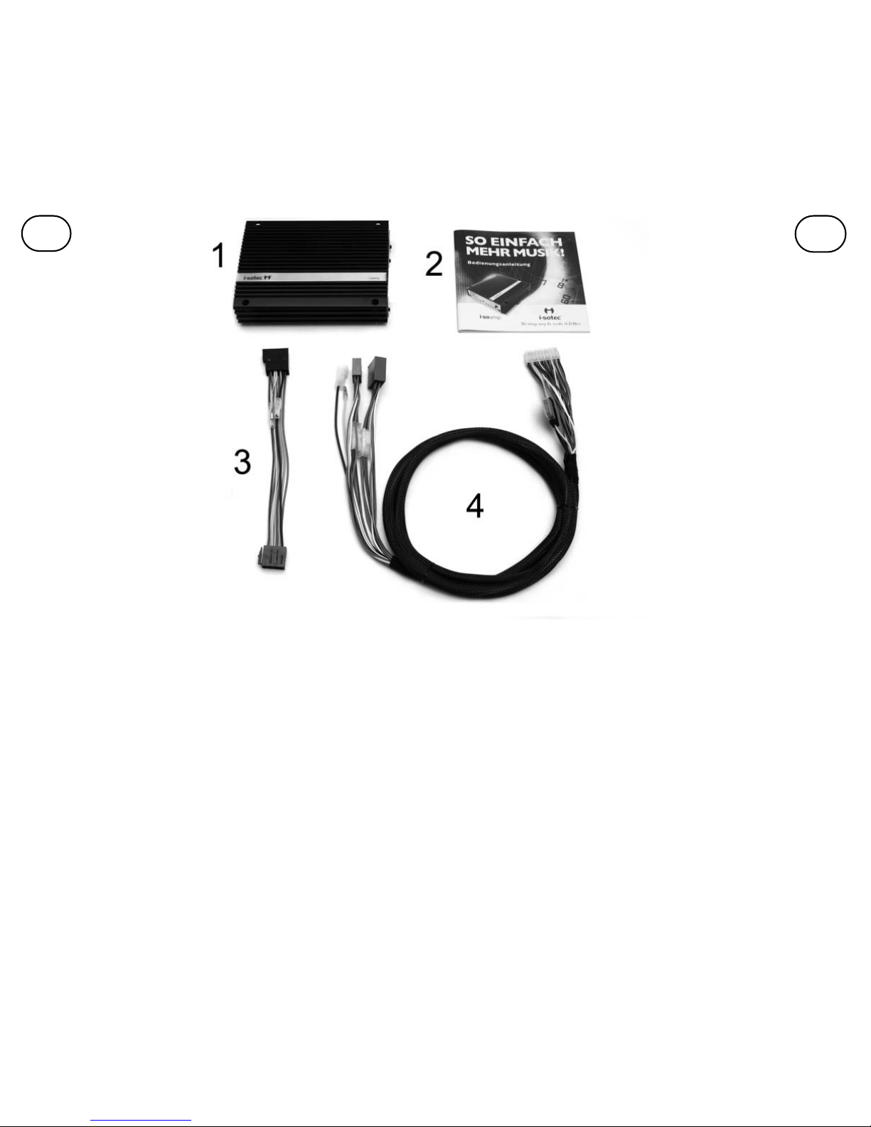
A.1.6 Connection to the power supply
The i-soamp and Auxgate are supplied with an ISO power adapter as
standard equipment.
The power adapter is connected between the car radio and the vehicle
cable harness.
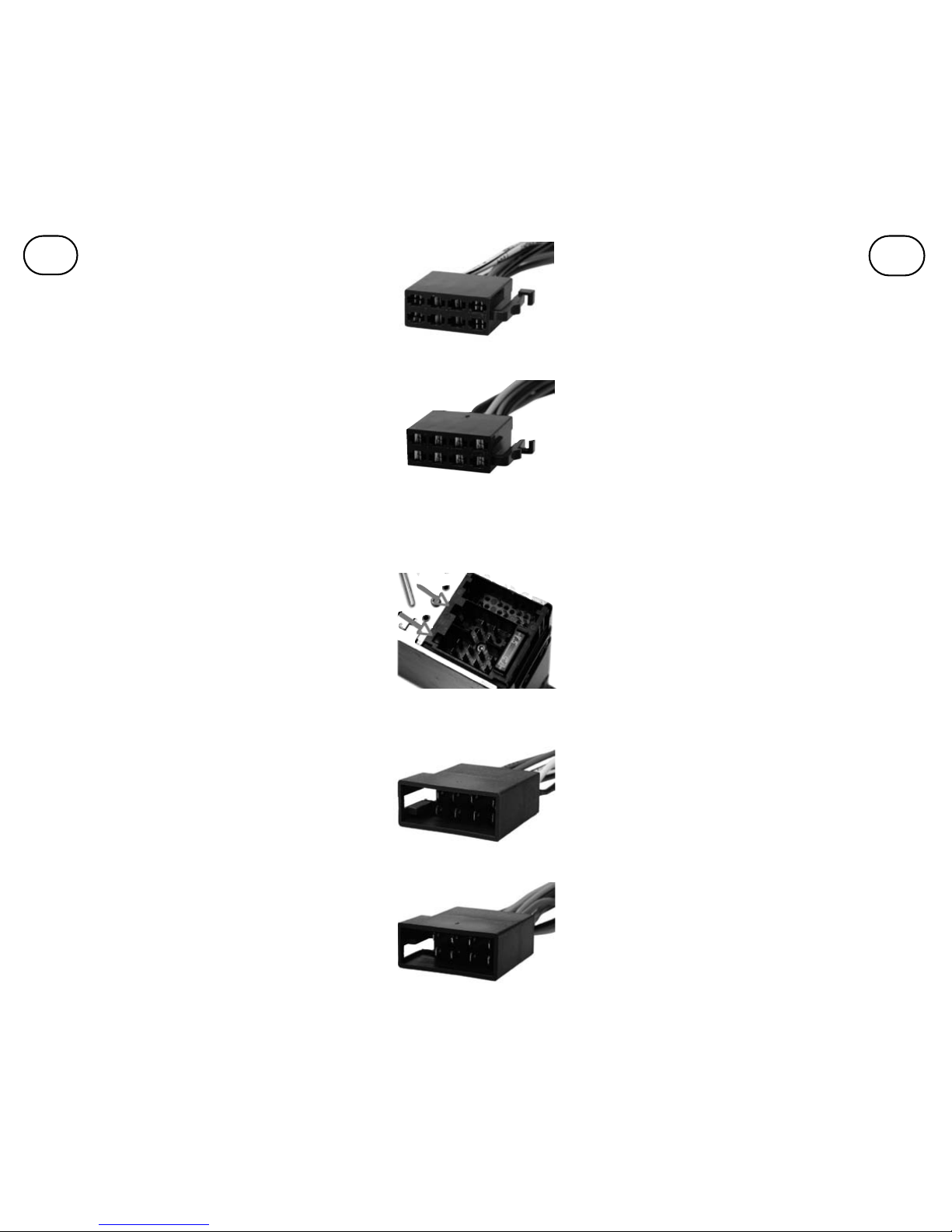
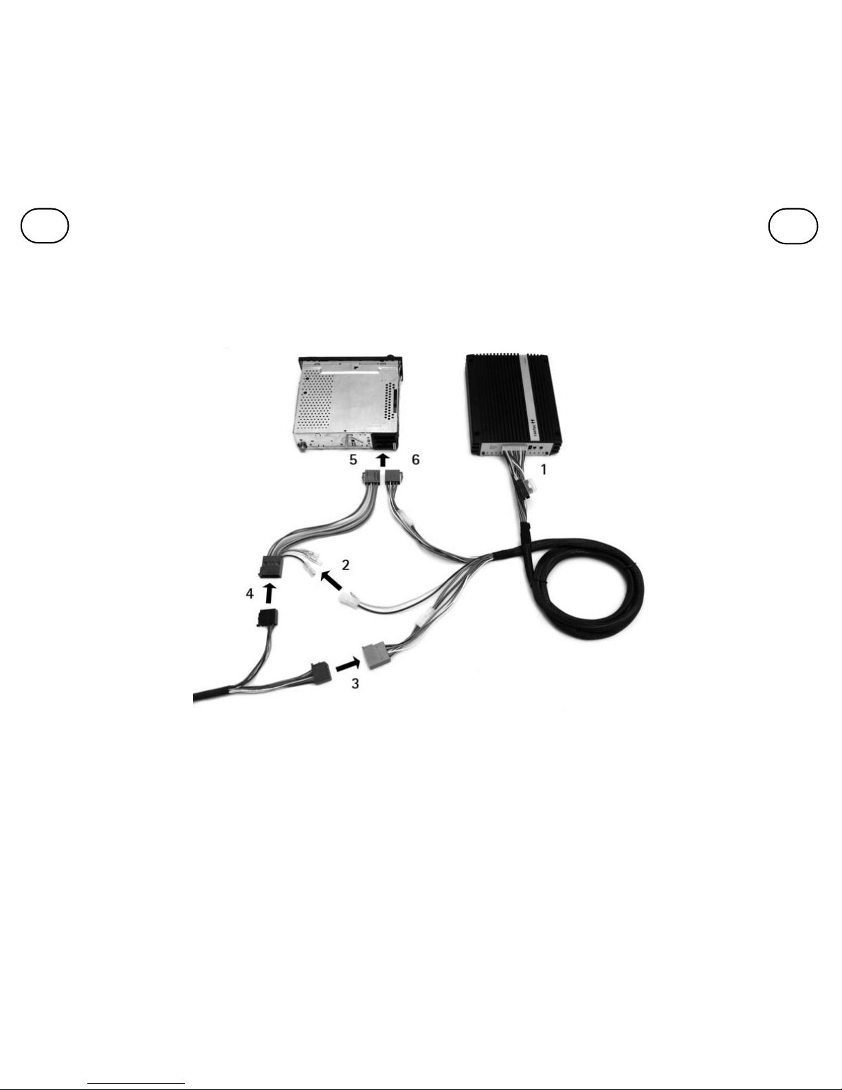
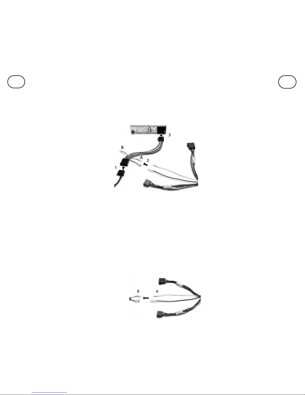
1. Remove the vehicle cable harness ISO power plug from the car radio and con-
nect it to the ISO power receptacle of the i-sotec power adapter.
2. Connect the 2-pole plug at the cable harness of the i-soamp to the 2-pole
receptacle at the power adapter. Other vehicle-specific adapters can be connec-
ted to the i-soamp with this plug-in connection.
3. Connect the ISO power plug of the i-sotec power
adapter to the ISO power receptacle of the car radio.
Since different vehicle manufacturers switch the connec-
tions at the ISO plug for 12V positive plus (memory, yel-
low) and 12V supply voltage (coupled to the ignition,
red), the i-sotec power adapter has two alternative
plug-in connectors for positive plus:
A. Standard connection for positive plus (as delivered)
B. Alternative coupling for positive plus
In case of doubt, the correct assignment can be checked
with a voltmeter or test lamp. The 1-pin coupling (A or
B) at which one measures against ground even with
switched off ignition +12V current, is to be connected
to the corresponding 1-pin plug.
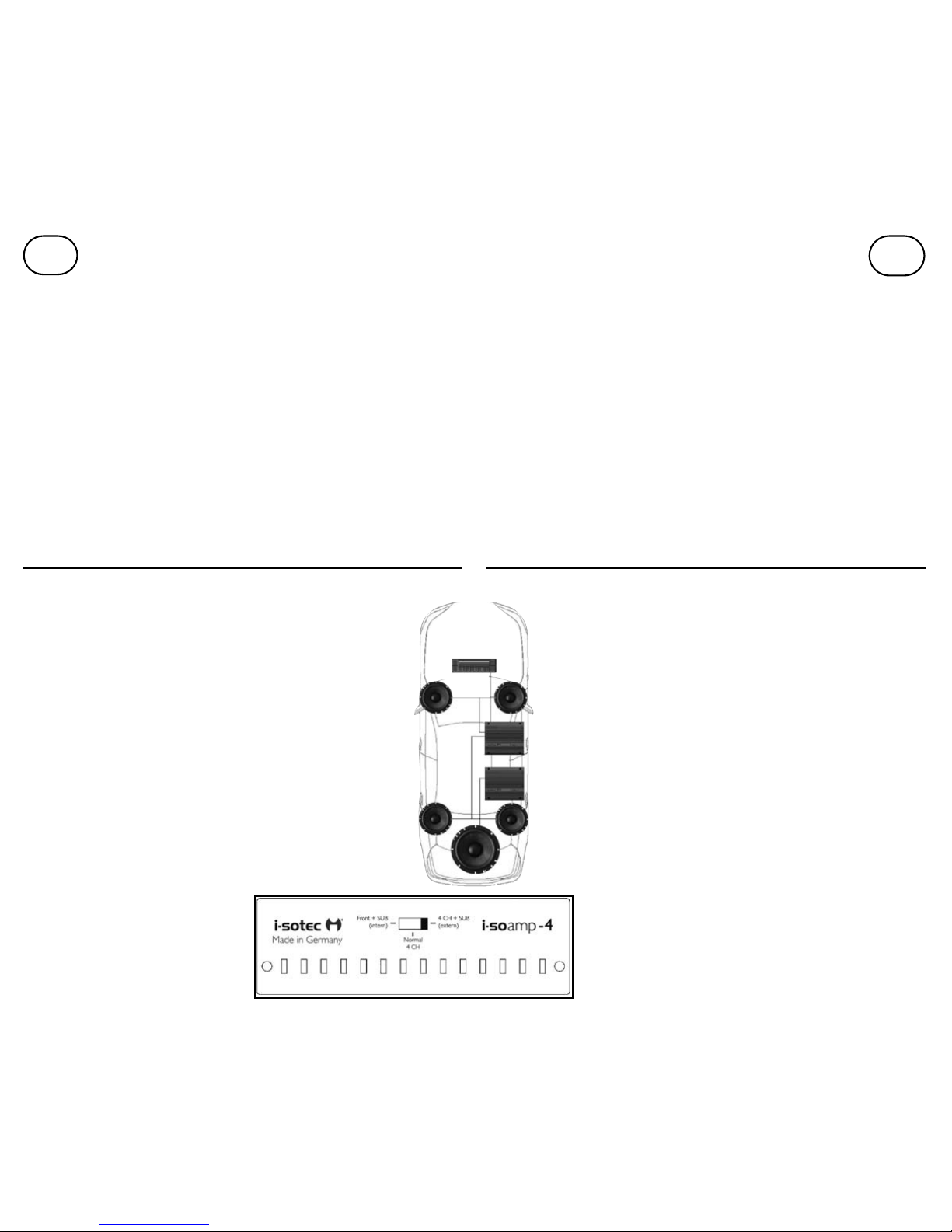
A.1.7 Direct connection to the battery
Under certain circumstances, the i-soamp amplifiers must be connected directly
to your car's battery. This is the case if you have trouble covering the power
requirement of the i-soamp amplifier with the supplied ISO power adapter or if
you deploy several i-soamp amplifiers in your vehicle.
For a direct connection of the i-soamp amplifier to the vehicle battery,i-sotec
recommends using the i-sotec power connector cable "AD-0125."
Important: Before connecting the device to your car's 12 V electrical system, be
sure to disconnect the battery!
1. The power connector cable must be run within the vehicle so that the end of
the cable with the adapter plug is located at the end of the i-soamp cable har-
ness and the other cable end near the car battery.It is important to ensure that
the cable is run without kinks. Avoid contact with sharp edged metal parts; rub-
ber grommets are recommended. If necessary, the power connector cable can be
shortened at the end close to the battery after success-
fully running it.
Note: The black cable inside the power connector
cable is used to connect the ground contact; the red
cable is used to connect to +12V.
2. A suitable ground connection point on the chassis
must be found to connect the black cable. The ground
connection point must have perfect contact with the
chassis and the battery's negative terminal. Make sure
this is the case and that you have not selected a piece
A1.6 Anschluss der Spannungsversorgung
Der i-soamp wird mit einem ISO Stromadapter ausgeliefert. Der
Adapter wird zwischen Autoradio und Fahrzeug-Kabelbaum ange-
schlossen.
1. ISO-Stromstecker des Fahrzeugkabelbaums vom Autoradio trennen und an
der ISO-Stromkupplung des i-sotec Stromadapters anschließen.
2. 2-poligen Stecker am Kabelbaum des i-soamp mit der 2-poligen Kupplung
am Stromadapter verbinden. An dieser Steckverbindung können ggfs. auch
andere fahrzeugspezifische Adapter mit dem i-soamp verbunden werden.
3. ISO-Stromstecker des i-sotec Stromadapters mit der ISO-
Stromkupplung des Autoradios verbinden.
Da verschiedene Fahrzeughersteller die Anschlüsse für 12V
Dauerplus (Memory, gelb) und 12V Versorgungsspannung
(an Zündung gekoppelt, rot) am ISO-Stecker vertauschen,
besitzt der i-sotec Stromadapter zwei alternative
Steckverbindungen für Dauerplus:
A. Standardanschluss für Dauerplus (Auslieferungszustand)
B. Alternative Kupplung für Dauerplus
Die korrekte Zuordnung ist im Zweifelsfall mit einem
Voltmeter oder Prüflampe zu testen. Diejenige 1-polige
Kupplung (A oder B), an der auch bei ausgeschalteter
Zündung +12V Spannung gegen Masse gemessen wird, ist
mit dem zugehörigen 1-poligen Stecker zu verbinden.
A1.7 Direkter Anschluss der Batterie
Die i-soamp Verstärker müssen unter bestimmten Umständen direkt an der
Batterie Ihres Fahrzeugs angeschlossen werden. Dies ist der Fall, wenn Sie
Schwierigkeiten damit haben, den Strombedarf des i-soamp über den mitgelie-
ferten ISO-Stromadapter zu decken oder wenn Sie mehrere i-soamp Verstärker
in Ihrem Fahrzeug einsetzen. i-sotec empfiehlt für den direkten Anschluss des i-
soamp Verstärkers an der Fahrzeugbatterie das i-sotec Stromanschlusskabel
„AD-0125“ zu verwenden.
Wichtig: Vor dem elektrischen Anschluss des Gerätes an das 12V Bordnetz Ihres
Fahrzeuges muss die Fahrzeugbatterie abgeklemmt werden!
1. Das Stromanschlusskabel ist im Fahrzeug so zu verlegen, dass das Kabelende
mit dem Adapterstecker am Ende des i-soamp Kabelbaums und das andere
Ende in der Nähe der Autobatterie liegt. Es ist darauf zu achten, dass das Kabel
knickfrei verlegt wird. Kontakt mit scharfkantigen Blechteilen ist zu vermeiden,
die Verwendung von Gummi-Durchführungen wird empfohlen. Falls notwendig,
kann das Stromanschlusskabel nach der Verlegung am Ende in der
Nähe der Batterie gekürzt werden.
Anmerkung: Das schwarze Kabel innerhalb der Ummantelung des
Stromanschlusskabels dient zum Anschluss des Massekontakts, das
rote Kabel wird für den Anschluss an +12V verwendet.
2. Zum Anschluss des schwarzen Kabels ist ein geeigneter
Massepunkt zu suchen. Er muss einwandfreien Kontakt zum Chassis
und dem Minuspol der Batterie haben. Stellen Sie sicher, dass dies der
Fall ist und Sie nicht ein Blech wählen, das evtl. nur ans Fahrzeug-
chassis geklebt wurde. Das schwarze Kabel wird an dem Massepunkt
DUK