Equipment arrival
Upon arrival user should thoroughly inspect the equipment and make sure there was no damage caused by the shipping carrier.
Product application
SF-1000 welding table can be operated without restriction in the technical areas intended for permanent human habitation. SF-1000
is designed for extraction and purication of air from the dry dust (with particular emphasis on the processes of welding, grinding,
polishing, pouring, dispensing, grinding, cutting metals and plastics).
Construction
• check overall state of delivery
• store in dry and airy space
•level before installation
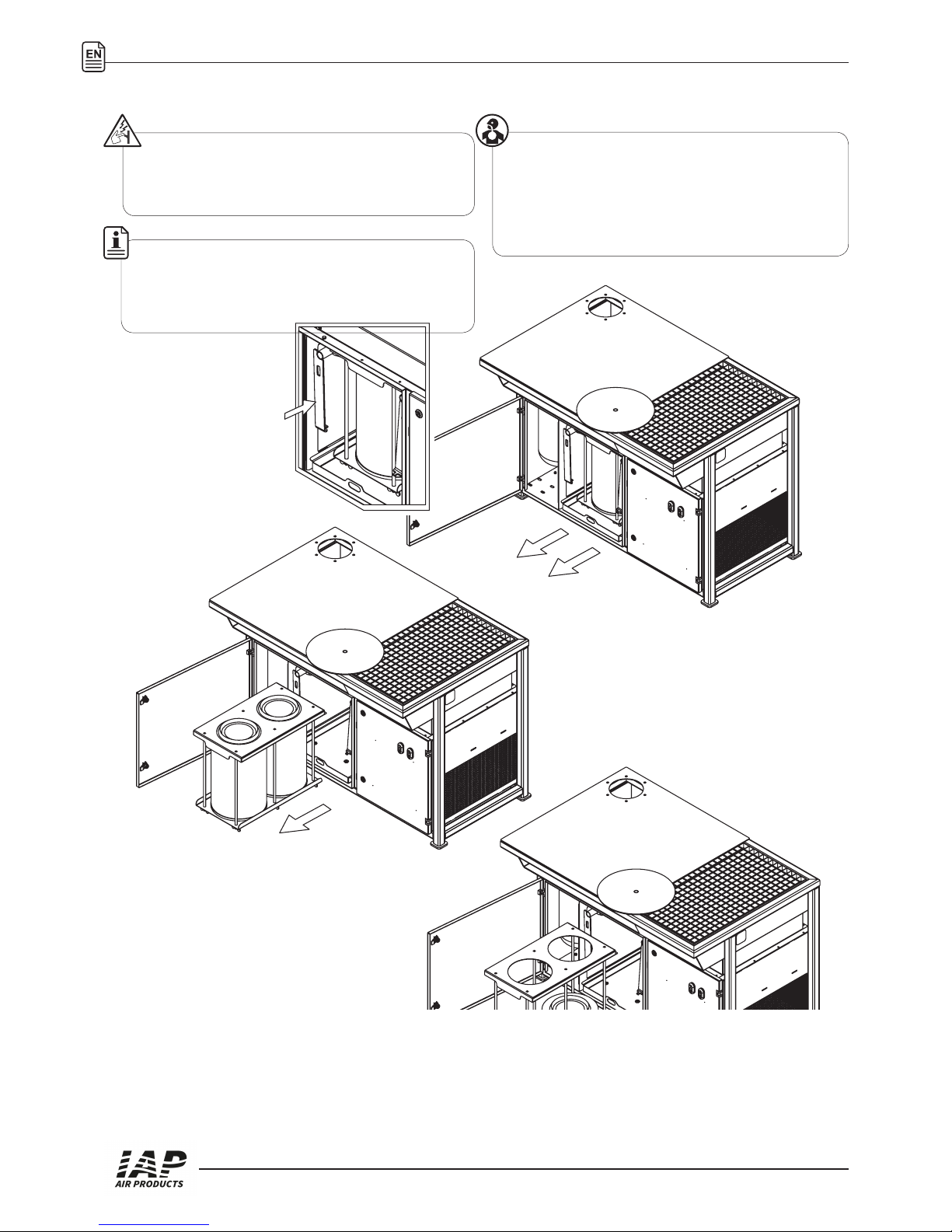
Due to the extremely harmful to the
health ne dust, located inside the
lter and on lter cartridges, all work
associated with the lter exchange
should be done using respiratory
protective equipment.
The manufacturer does not recommend use of the unit in the
process of:
•air purication from dust containing asbestos, cadmium,
beryllium
• air cleaning with wet dust
• air cleaning with aggressive and explosive dusts
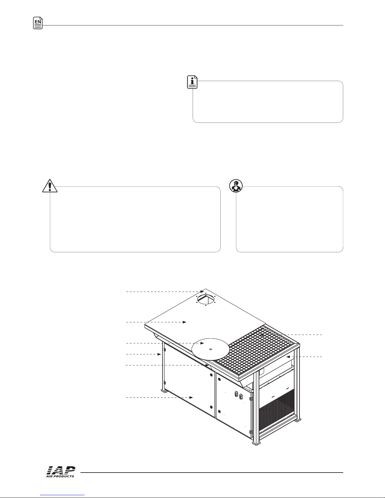
1. S-1000 frame
2. Revolving table (option)
3. Welding deck
4. Carrier shelf
5. Lower exhaust grate
6. Damper
7. Arm mounting place
8. Crawlair lter unit:
- Metal mesh lter
- Filter cartridge
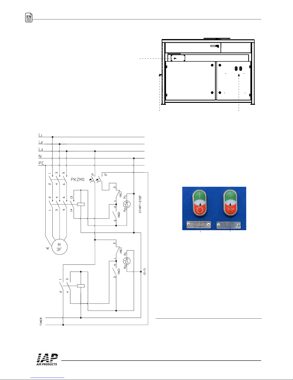
9. Electrical set