IBM Emulex 4 Gb User manual

Emulex 4Gb Fibre Channel Host Bus Adapters for IBM
System xQuick Installation Guide
Before using this information and the product it supports, read the “IBM Statement of Limited Warranty”
in the IBM
®
Emulex 4Gb Fibre Channel Host Bus Adapters for IBM System x
™
Installation and User’s Guide on
the IBM Documentation and Support CD that comes with the host bus adapter.
This Quick Installation Guide provides information about installing and configuring an Emulex 4Gb Fibre
Channel Single-Port or Dual-Port PCI-X or PCIe host bus adapter. For more information, see the
Installation and User’s Guide on the IBM Documentation and Support CD.
Hardware and software requirements
The host bus adapter requires the following minimum hardware and software:
vThe server must have one of the following slots:
–For aPCI-X 2.0 host bus adapter:
-PCI 32/64-bit data and 33/66 MHz clock frequency, 3.3 Vsignaling
-PCI-X Mode 164-bit data and 66/100/133 MHz clock frequency
-PCI-X Mode 264-bit data and 266 MHz (133 MHz clock frequency, double data rate)
-3.3 Vand 5VPCI power required for operation
–For aPCI Express (PCIe) host bus adapter:
-x1 or x4 lane transfer link interface at 2.5 Gbps per lane
-3.3 Vpower required for operation
vThe server must have one of the following operating systems:
–Microsoft
®
Windows
®
Server 2003, Advanced Server, or Enterprise Edition
–Novell Netware version 6.5
–Red Hat
®
Enterprise Linux
®
Advanced Server or Enterprise Server version 4
–SUSE Linux Enterprise Server version 8or version 9
–VMware ESX Server 2.5 or 3.0
Option package contents
The host bus adapter option package includes the following items. If any items are missing or damaged,
contact your place of purchase.
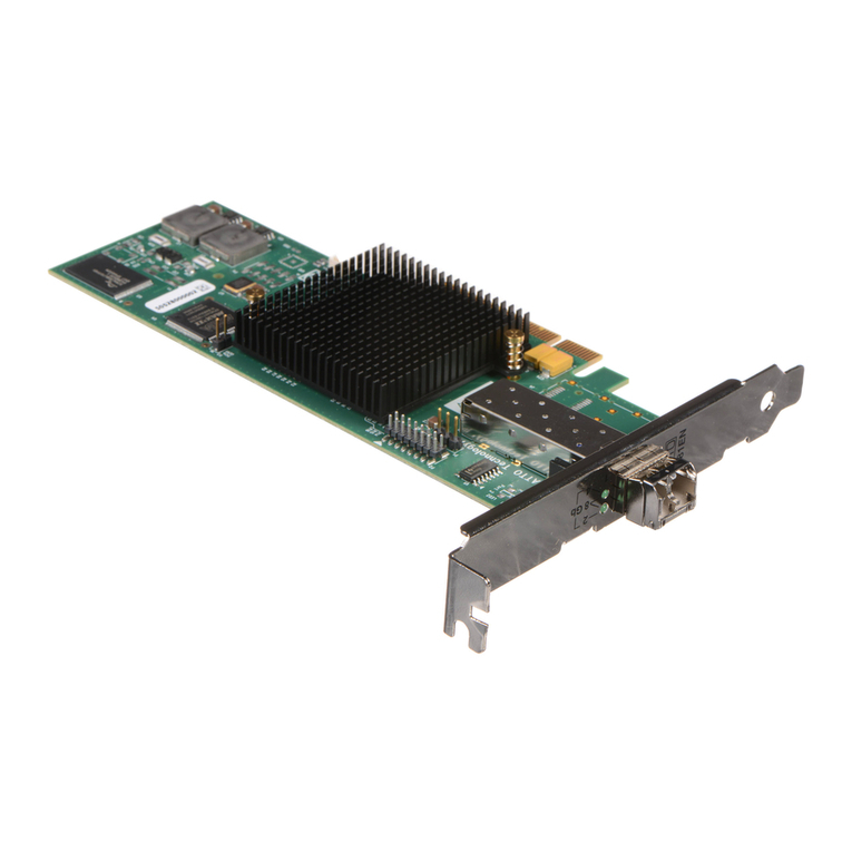
vOne of the following host bus adapters:
–Emulex 4Gb FC Single-Port PCI-X HBA for IBM System x
–Emulex 4Gb FC Dual-Port PCI-X HBA for IBM System x
–Emulex 4Gb FC Single-Port PCIe HBA for IBM System x
–Emulex 4Gb FC Dual-Port PCIe HBA for IBM System x
v
One low-profile expansion slot bracket
vThis Quick Installation Guide
vOne IBM Documentation and Support CD (includes the Installation and User’s Guide and the IBM Systems
Safety Notices document)

Installing the host bus adapter
DANGER
When working on or around the system, observe the following precautions:
Electrical voltage and current from power, telephone, and communication cables are hazardous. To
avoid ashock hazard:
vConnect power to this unit only with the provided power cord. Do not use the provided power
cord for any other product.
vDo not open or service any power supply assembly.
vDo not connect or disconnect any cables or perform installation, maintenance, or reconfiguration
of this product during an electrical storm.
vThe product might be equipped with multiple power cords. To remove all hazardous voltages,
disconnect all power cords.
vConnect all power cords to aproperly wired and grounded electrical outlet. Ensure that the outlet
supplies proper voltage and phase rotation according to the system rating plate.
vConnect any equipment that will be attached to this product to properly wired outlets.
vWhen possible, use one hand only to connect or disconnect signal cables.
vNever turn on any equipment when there is evidence of fire, water, or structural damage.
vDisconnect the attached power cords, telecommunications systems, networks, and modems before
you open the device covers, unless instructed otherwise in the installation and configuration
procedures.
vConnect and disconnect cables as described in the following procedures when installing, moving,
or opening covers on this product or attached devices.
To disconnect:
1. Turn off everything (unless instructed otherwise).
2. Remove the power cords from the outlets.
3. Remove the signal cables from the connectors.
4. Remove all cables from the devices.
To connect:
1. Turn off everything (unless instructed otherwise).
2. Attach all cables to the devices.
3. Attach the signal cables to the connectors.
4. Attach the power cords to the outlets.
5. Turn on the devices.
(D005a)
2

To install the host bus adapter in the server, complete the following steps:
1. Read the IBM Systems Safety Notices document on the IBM Documentation and Support CD.
2. Turn off the server and peripheral devices, disconnect the power cords, and remove the server cover.
3. Determine which PCI-X slot (32-bit or 64-bit) or PCIe slot (x1 or x4) you will use. For information
about the slot type and specification, see the server documentation.
4. Remove the expansion-slot cover by removing the expansion-slot screw or releasing the bracket
lever.
5. Remove the host bus adapter from the static-protective package. Do not place the host bus adapter
on the server cover or on ametal surface.
6. If you have to remove the preinstalled expansion-slot bracket and replace it with the low-profile
bracket, complete the following steps; otherwise, go to step 7.
a. Use asmall Phillips screwdriver to carefully remove the two screws from the bracket, and set the
screws and bracket aside for later use.
b. Align the two screw holes on the low-profile bracket with the holes on the host bus adapter;
then, attach the bracket to the host bus adapter, using the two screws that you removed in step
6a.
7. Position the host bus adapter by aligning the PCI-X or PCIe connector with the PCI-X or PCIe slot
on the system board. Insert the host bus adapter firmly into the connector.
8. Secure the host bus adapter to the server chassis with the expansion-slot screw, if you removed it in
step 3, or return the bracket lever to the closed position.
CAUTION:
This product might contain one or more of the following devices: CD-ROM drive, DVD-ROM
drive, DVD-RAM drive, or laser module, which are Class 1laser products. Note the following
information:
vDo not remove the covers. Removing the covers of the laser product could result in exposure to
hazardous laser radiation. There are no serviceable parts inside the device.
vUse of the controls or adjustments or performance of procedures other than those specified
herein might result in hazardous radiation exposure.
(C026)
CAUTION:
Data processing environments can contain equipment transmitting on system links with laser
modules that operate at greater than Class 1power levels. For this reason, never look into the end
of an optical fiber cable or open receptacle. (C027)
9. Connect one end of an LC-LC fiber-optic cable to the optical interface connector on the host bus
adapter. Connect the other end to the Fibre Channel device.
10. Replace the server cover and reconnect the power cords.
11. Turn on all external Fibre Channel devices; then, turn on the server. To be sure that the host bus
adapter is functioning correctly, check the amber and green LEDs on the front bracket of the host bus
adapter. For more information about the host bus adapter LEDs, see the Installation and User’s Guide.
For detailed information about how to install the host bus adapter device drivers and how to update the
host bus adapter boot code and firmware, see Chapter 3in the Installation and User’s Guide.
3
First Edition (October 2006)
IBM and System xare trademarks of International Business Machines Corporation in the United States, other
countries, or both.
Microsoft and Windows are trademarks of Microsoft Corporation in the United States, other countries, or both.
Linux is atrademark of Linus Torvalds in the United States, other countries, or both.
Red Hat, the Red Hat “Shadow Man” logo, and all Red Hat-based trademarks and logos are trademarks or registered
trademarks of Red Hat, Inc., in the United States and other countries.
Other company, product, or service names may be trademarks or service marks of others.
©Copyright International Business Machines Corporation 2006. All rights reserved.
US Government Users Restricted Rights –Use, duplication or disclosure restricted by GSA ADP Schedule Contract
with IBM Corp.
(1P) P/N: 42D8969
Table of contents
Other IBM Host Adapter manuals
Popular Host Adapter manuals by other brands

ATTO Technology
ATTO Technology Celerity FC-41EL Installation and operation manual

HP
HP Tc2110 - Server - 128 MB RAM Installation and configuration guide

Initio
Initio INI-9090U user manual

EMC
EMC QLogic user guide

ATTO Technology
ATTO Technology ATTO Celerity FC-42XS Specification sheet

ATTO Technology
ATTO Technology ExpressPCI UL4S Technical specifications

HP
HP A8002A Quickspecs

Adaptec
Adaptec AHA-F940 installation guide

ATTO Technology
ATTO Technology ATTO ExpressPCI FC 3305 Specification sheet

ATTO Technology
ATTO Technology ExpressPCI UL5D Technical specifications

ATTO Technology
ATTO Technology 6-Gb SAS/SATA Host Adapter H60F Specification sheet

LSI
LSI LSI7102XP-LC user guide