manuals.online logo
Brands
  1. Home
  2. •
  3. Brands
  4. •
  5. ICI Caldaie
  6. •
  7. Boiler
  8. •
  9. ICI Caldaie BNX Series User manual

ICI Caldaie BNX Series User manual

BNX_100_3000_EN Ed. 08 - 03/2019
EN
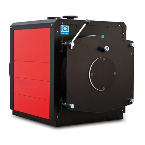
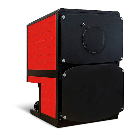
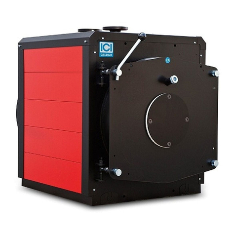
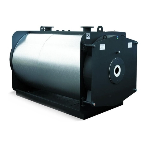
Low-pressure reverse flame steam boiler
BNX
INSTALLATION, USE AND MAINTENANCE MANUAL
Cooke Industries - Phone: +64 9 579 2185 Email: [email protected] Web: www.cookeindustries.co.nz
2
INDEX
SYMBOLS USED IN THE MANUAL
aDANGER
To indicate actions that, if not performed correctly, can result in injury of generic origin or may generate malfunction
or damage to the appliance; therefore require particular caution and adequate preparation.
dIT IS FORBIDDEN
To indicate operations that SHOULD NOT be performed.
mIMPORTANT
To indicate particularly useful information and important.
The illustrations and data presented are not binding. The company reserves the right to make without prior notice any changes it
deems appropriate for continuous improvement and constant updating.
General information
3 Introduction
3 Range
3 Compliance
4 Warnings
5 Prohibitions
5 Hazards
6 Identification
7 Appliance description
7 Structure
8 Dimensions and connections
9 Technical data
10 Control panel
10 Alarm viewer
11 Burners
12 Paperwork
12 Fire prevention
13 Components
13 Pressure
16 Level
Installation
18 Product receipt
19 Handling
19 Film removal
20 Installation room
20 Positioning
20 Room ventilation
21 System cleaning
21 Hydraulic connections
21 Flue exhaust
22 Front door opening
22 Door opening reversal (to the right)
24 Front door adjustment
25 Turbulator assembly
26 Burner assembly
26 Electrical connections
27 Loading and supply of the generator/system
27 Hydrostatic head diagram
28 Water characteristics
29 Frequency of analysis
Use
30 Preliminary checks
30 Commissioning
31 Checks after commissioning
31 Mandatory periodic verifications
31 Stop periods
Maintenance
32 Periodic verifications
33 Methods for checking the safety devices
33 Checking of the minimum level safety level switches
33 Checking of the maximum level switch
33 Check of the safety pressure switch
34 Routine maintenance
34 Extraordinary maintenance
34 Level switch replacement
35 Any anomalies and remedies
35 Environmental protection and disposal
35 Information for the disposal of electrical and
electronic equipment
Residual Risk Management
Useful information and declarations
40 QR code
Notes
Cooke Industries - Phone: +64 9 579 2185 Email: [email protected] Web: www.cookeindustries.co.nz
General information 3
1 General information
INTRODUCTION
Dear Customer,
Thank you for having chosen an appliance of the series
BNX
, a high quality and efficiency product, reliable and safe.
We recommend entrusting its maintenance to
Professionally Qualied Personnel
who, when necessary, uses original spare parts.
This manual contains important information and suggestions that must be observed for easier installation and best possible use
of the appliance.
mIMPORTANT
Failure to observe the instructions in this manual will void the warranty conditions.
RANGE
MODEL CODE MODEL CODE MODEL CODE
BNX 0,98 bar BNX 0,98 bar BNX 0,98 bar
BNX 100 86420100 BNX 700 86420700 BNX 1700 86421700
BNX 150 86420150 BNX 850 86420850 BNX 2000 86422000
BNX 350 86420350 BNX 1000 86421000 BNX 2650 86422650
BNX 500 86420500 BNX 1400 86421400 BNX 3000 86423000
BNX EXP 0,98 bar BNX EXP 0,98 bar BNX EXP 0,98 bar
BNX EXP 100 86420104 BNX EXP 700 86420704 BNX EXP 1700 86421704
BNX EXP 150 86420154 BNX EXP 850 86420854 BNX EXP 2000 86422004
BNX EXP 350 86420354 BNX EXP 1000 86421004 BNX EXP 2650 86422654
BNX EXP 500 86420504 BNX EXP 1400 86421404 BNX EXP 3000 86423004
BNX EXP 0,7 bar BNX EXP 0,7 bar BNX EXP 0,7 bar
BNX 100 86420106 BNX 700 86420706 BNX 1700 86421706
BNX 150 86420156 BNX 850 86420856 BNX 2000 86422006
BNX 350 86420356 BNX 1000 86421006 BNX 2650 86422656
BNX 500 86420506 BNX 1400 86421406 BNX 3000 86423006
COMPLIANCE
The steam generators Series
BNX
comply with the following European Directives:
–Directive 2014/68/EU (PED)
–Low Voltage Directive 2014/35/EU
–Electromagnetic Compatibility Directive 2014/30/EU
NOTE
The serial number is indicated on the boiler nameplate.
Cooke Industries - Phone: +64 9 579 2185 Email: [email protected] Web: www.cookeindustries.co.nz
General information4
WARNINGS
mIMPORTANT
–The instructions manual is an integral and essential part of the product. If the body is sold or transferred to a new owner
or if you relocate and leave the system, always make sure that the manual accompanies the boiler body, so that it can be
consulted by the new owner and/or by the installer. In case of damage or loss, request a copy from Technical Assistance
Service
ICI CALDAIE S.p.A.
. This body must be intended for the use it was expressly designed for. The manufacturer will
be exempted from any liability, contractual and extra-contractual, for any injury/damage caused to people, animals, or
property due to the failure to perform maintenance and/or scheduled periodic checks and improper uses.
–Upon receipt of the generator, make sure that the supply is intact and undamaged and promptly contact
ICI CALDAIE
S.p.A.
if it does not correspond to the order
–The installation of
BNX
generator must be performed by a Certified Company which, at the end of the operation, must
provide the owner with the declaration of conformity certifying that the installation has been correctly carried out, namely
in compliance with the Standards and the national and local Laws in force, and with the indications included in the
instruction manuals supplied by
ICI CALDAIE S.p.A.
–If the appliance is not used for a long period, professionally qualified personnel must intervene to perform the operations
described in the specific paragraph, necessary for storing the steam generator.
–The periodic check and maintenance of the appliance is a legislative obligation. The User must have it performed by
professionally qualified personnel.
–Make sure the safety valves properly open at the design pressure.
–It is necessary to check the correct activation of the safety pressure switch that eliminates the cause of pressure increase by
stopping the flow in the burner.
–Check the correct connection of the accessories to the boiler body (gasket seal check).
–Pay the due attention during handling and installation.
–Periodically check the condition of the same accessories (exclusion of fractures).
Once installation is completed, check the intervention of the safety valve by carrying out a preventive hydraulic test (at
the PT pressure indicated on the ID plate).
–Make sure the safety level switch is working properly, in accordance with the contents of the technical manual supplied
with the boiler.
–It is necessary to check that the operating water conductivity values are within those provided in the supplied technical
manual.
–Make sure the water loading pump is working properly as described in the technical manual provided with the boiler
(pump wear, hydrostatic head in suction, water supply temperature, pump connection/disconnection from the level
control probes).
–Analyse the water when necessary, ascertaining that the values are within the limits expressed in this technical manual
and carry out the due chemical treatments. Check the intervention of the safety probes by lowering the level below the
minimum required.
Manually check that the level switch is working properly every 6 hours.
–Do not step on or damage the protective sheath of the cable with any other mean.
–It is not necessary to consider the boiler connections as support points for the weight of the pipes.
–It is good practice to provide expansion joints and appropriate supports for the pipes connecting the boiler to the system
–Check that the panel power supply complies with the wiring diagram supplied.
–Make sure the generator is properly earthed.
–Check the plant’s electrical system.
–Before opening the inspection outlets, it is necessary to check that the pressure in the boiler body is equal to the atmospheric
one (0 relative bar).
–Before opening the door, check that the burner is off and disconnected.
–Switch off the burner and the pump before closing the shut-off valve.
–Avoid contact with the non-insulated parts of the equipment during its operation. When adjustments or checks are carried
out during operation, it is necessary to protect oneself with suitable clothing (P.P.E. according to Italian Legislative Decree
81/08).
Cooke Industries - Phone: +64 9 579 2185 Email: [email protected] Web: www.cookeindustries.co.nz
General information 5
mIMPORTANT
–Pay attention to sharp edges on the generator and its accessories.
–The boiler must be kept sheltered from adverse weather conditions, with regard to the minimum temperature (-10 ° C) and
from the rain.
–The user is responsible for considering the seismic degree of the user area in the design of the heating plant.
–After an earthquake, have technical personnel assess any damage by carrying out NDCs (non-destructive checks), if
necessary.
–The manufacturer shall not be held liable in the event of accidents caused by incorrect decommissioning.
–The personnel in charge must be able to prove to have sufficient knowledge and experience relating to the safety and
control / regulation accessories supplied with the generator and good familiarity with the instructions contained in the use
and maintenance manual and be capable and physically suitable.
–During handling, always maintain a distance of at least 5 m from the projection of the appliance to the ground
–In case of violent impact during handling, visually check the integrity of the appliance, all over; run the hydraulic test again.
–
The generators are sized only for loads due to pressure, temperature and contained uid.
PROHIBITIONS
dIT IS FORBIDDEN
–Operate electrical devices or appliances such as switches, household appliances, etc. if you smell fuel or unburnt materials.
In this case:
-
ventilate the room by opening doors and windows
-
close the fuel shut-off device
–Perform any technical or cleaning intervention before disconnecting the appliance from the electrical power supply and
wearing the Personal Protective Equipment (P.P.E. according to Italian Legislative Decree 81/08).
–Modifying safety or adjustment devices without the boiler manufacturer’s authorisation and indications.
–Plug or dimensionally reduce the ventilation openings of the installation room. The ventilation openings are essential for
proper combustion.
–Perform any welding/repairs. If necessary, contact the manufacturer/verifying party for operation (in Italy according to MD
329/04).
–Expose the generator to atmospheric agents.
–Leave flammable substances and containers in the room where the appliance is installed.
–Disperse the packaging material in the environment and leave it within the reach of children as it may be a potential source
of danger. It must be disposed of in accordance with the legislation in force.
HAZARDS
aDANGER
–Dangers due to
water leaks
. Disconnect the boiler from the electrical power supply, close the water supply and promptly
contact the Technical Assistance Service Authorised
ICI CALDAIE S.p.A.
or professionally qualified personnel.
–
Danger of explosion.
Routine and extraordinary maintenance must be entrusted to
professionally qualied personnel
with the purpose of promptly detecting any damage to the generator's pressurised body and the safety and control
accessories.
Cooke Industries - Phone: +64 9 579 2185 Email: [email protected] Web: www.cookeindustries.co.nz
General information6
aDANGER
–
Danger deriving from the fuel.
Sensing the presence of fuel in the thermal power plant, it is appropriate to follow the
precautions below to avoid the risk of explosions and fires:
-
do not smoke or cause sparks
-
do not turn on lights or electrical devices in general (mobile phones)
-
open doors and windows
-
close the fuel shut-off valve normally placed outside the thermal power plant
-
disconnect the electrical power supply by using the switch normally placed outside the thermal power plant.
–
Danger of burns.
During normal operation, the generator has hot parts that, upon accidental contact without suitable
personal protection, can cause serious burns. Potentially hot parts include:
-
accessories and valves connected to the generator
-
door and smoke chamber
-
upper tread walkway.
–
Danger from fumes.
An incorrect adjustment of the closing door or an insufficient draught in the flue can leave fumes
inside the thermal power plant, causing fatal intoxication deriving from carbon monoxide which, by its nature, is colourless
and odourless. Therefore, ensure the generator is properly installed and adjusted and the presence of ventilation openings
in the thermal power plant are compliant with the regulations in force.
IDENTIFICATION
Each generator
BNX
is identified by the following nameplates:
–
Boiler body nameplate (1)
: this plate carries the boiler body main data and is riveted on a special support.
–
Assembly nameplate (2)
: this plate carries the data relating to the boiler complete with the accessories, which may vary from
those of the boiler body only.
12
The appliance is also accompanied by
construction certicate
attesting the successful result of the hydraulic test.
mIMPORTANT
The installation must be carried out in compliance with the local applicable regulations by
professionally qualied
personnel
, ie personnel having specific technical skills in the steam production system component sector. An
incorrect installation can harm people or damage property for which the manufacturer cannot be liable.
During
commissioning
check the effectiveness of all adjustment and control devices in the control panel.
The
warranty
validity is subject to compliance with the instructions in this manual.
Cooke Industries - Phone: +64 9 579 2185 Email: [email protected] Web: www.cookeindustries.co.nz
General information 7
APPLIANCE DESCRIPTION
The
BNX
steam generators are automatically operated single-block appliances.
The horizontal combustion chamber is with flame inversion and the tube bundle is complete with helical turbulators.
The single front door is thermally insulated with refractory materials and is mounted on adjustable hinges, easily opened without
having to remove the burner; it is equipped with visor for flame control.
The smoke box is fixed with bolts to the back of the generator. It is equipped with smoke duct fitting, cleaning door and can be
dismantled.
The body is thermally insulated with high density rock wool mat, protected with stainless steel panels.
They use a single control panel in which the entire electrical wiring converges.
The appliance rests on a carbon steel profile base that ensures its stability.
The
BNX
steam generators have obtained suitability for liquid and gaseous fuels for the production of low pressure (0,7-0,9 bar)
100 to 3000 kg/h steam.
STRUCTURE
1
Electrical panel
2
Adjustment pressure switch(es)
3
Block pressure switch
4
Pressure gauge
5
1st safety level probe (minimum)
6
Level adjustment probes (start/stop)
7
2nd safety level probe (minimum)
8
Level indicator
9
Level indicator discharge
10
Front door
11
Level test valves
12
Flame control warning light
13
Burner application plate
14
Steam inlet valve
15
Steam dome
16
Inspection hatch
17
Safety valve
18
Supply filter
19
Rear smoke chamber
20
Chimney fitting
21
Cleaning door
22
Drain valve
23
Supply electric pump (2 electric
pumps only for EXP versions)
24
Check valves
25
Supply valve
26
Auxiliary supply valve
27
Pressure gauge valve
N1
Steam inlet
N2
Supply
N3
Safety valve drain
N4
Boiler drain
N5
Safety valve connection
N6
Auxiliary supply
Cooke Industries - Phone: +64 9 579 2185 Email: [email protected] Web: www.cookeindustries.co.nz
General information8
DIMENSIONS AND CONNECTIONS
Dimensions
Description u.m. BNX
100 150 350 500 700 850 1000 1400 1700 2000 2650 3000
H mm 1280 1465 1795 1790 1790 2045 2045 2325 2325 2760 2510 2510
H1 mm 905 995 1245 1290 1290 1465 1465 1640 1640 1855 1995 1995
H2 mm 385 420 575 585 585 630 630 685 685 810 850 850
H4 mm 1280 1460 1760 1665 1665 1560 1560 1760 1760 1960 2110 2110
H6 mm 485 560 720 760 760 800 800 835 835 1000 1080 1080
L mm 1000 1160 1340 1440 1440 1560 1560 1770 1770 1940 2100 2100
L2 mm 740 900 1080 1180 1180 1300 1300 1510 1510 1680 1840 1840
L4 mm 820 980 1160 1260 1260 1380 1380 1590 1590 1760 1920 1920
P mm 1225 1720 2060 2085 2335 2625 2625 2625 2925 3160 3720 3720
P2 mm 820 1170 1510 1510 1760 2010 2010 2010 2310 2515 3015 3015
P6 mm 240-290 280-330 280-330 310-360 310-360 350-400 350-400 370-420 370-420 370-420 420-470 420-470
Øb mm 130 160 180 225 225 280 280 280 280 320 360 360
Øc mm 180 200 250 250 250 300 300 350 350 400 450 450
Attachments
Description u.m. BNX
100 150 350 500 700 850 1000 1400 1700 2000 2650 3000
N1 DN/in 1"1/4 40 50 65 65 80 80 100 100 125 150 150
N2 DN/in 1" 1" 1" 1" 1" 1" 1" 1" 1" 1" 1" 1"
N3 DN/in 1" 40 65 80 100 125 125 125 150 150 125 125
N4 DN/in 1" 1" 1"1/4 1"1/4 1"1/4 1"1/4 1"1/4 1"1/4 1"1/4 1"1/4 1"1/4 1"1/4
N5 DN/in 3/4" 25 40 50 65 80 80 80 100 80 100 100
N6 DN/in 1" 1" 1" 1" 1" 1" 1" 1" 1" 1" 1" 1"
Cooke Industries - Phone: +64 9 579 2185 Email: [email protected] Web: www.cookeindustries.co.nz
General information 9
TECHNICAL DATA
DESCRIPTION u.m. BNX
100 150 350 500 700 850
Effective rated
[1]
kW 69,8 105 233 349 465 581
Thermal capacity
kW 77,4 115 256 383 511 639
Efficiency at 100% (ref. P.C.I.)
[1]
% 90,00 91,00 91,00 91,00 91,00 91,00
Pressure drops on exhaust side
mbar 0,7 1,5 3,5 3,5 5,0 4,5
Rated pressure
bar 0,98 0,98 0,98 0,98 0,98 0,98
Total capacity
l 198 410 805 875 995 1400
Capacity at level
l 146 250 515 690 800 1100
Exchange surface
m22,30 3,60 6,00 9,00 10,50 13,50
Steam production
[1]
kg/h 100 150 350 500 700 850
Rated frequency ~ voltage
Volt ~
Hz 1/N~ 230 ~ 50 1/N~ 230 ~ 50 1/N~ 230 ~ 50 3/N~ 400 ~ 50 3/N~ 400 ~ 50 3/N~ 400 ~ 50
Electric protection rating
IP 55 55 55 55 55 55
Absorbed electrical power
[2]
W 1500 1500 1500 6000 6000 6000
Allowed fuels
Methane -
LPG - Diesel
- Naphtha
Methane -
LPG - Diesel
- Naphtha
Methane -
LPG - Diesel
- Naphtha
Methane -
LPG - Diesel
- Naphtha
Methane -
LPG - Diesel
- Naphtha
Methane -
LPG - Diesel
- Naphtha
Total weight
kg 470 660 1080 1300 1400 2000
DESCRIPTION u.m. BNX
1000 1400 1700 2000 2650 3000
Effective rated
[1]
kW 698 897 1163 1395 1744 2035
Thermal capacity
kW 767 985 1278 1533 1917 2236
Efficiency at 100% (ref. P.C.I.)
[1]
% 91,00 91,00 91,00 91,00 91,00 91,00
Pressure drops on exhaust side
mbar 6,0 5,5 7,0 7,5 6,5 7,5
Rated pressure
bar 0,98 0,98 0,98 0,98 0,98 0,98
Total capacity
l 1400 2010 2280 3020 4240 4240
Capacity at level
l 1100 1560 1790 2050 3100 3100
Exchange surface
m215,50 22,00 26,00 31,00 42,00 46,00
Steam production
[1]
kg/h 1000 1350 1700 2000 2650 3000
Rated frequency ~ voltage
Volt ~
Hz 3/N~ 400 ~ 50 3/N~ 400 ~ 50 3/N~ 400 ~ 50 3/N~ 400 ~ 50 3/N~ 400 ~ 50 3/N~ 400 ~ 50
Electric protection rating
IP 55 55 55 55 55 55
Absorbed electrical power
[2]
W 6000 6000 9500 9500 12500 12500
Allowed fuels
Methane -
LPG - Diesel
- Naphtha
Methane -
LPG - Diesel
- Naphtha
Methane -
LPG - Diesel
- Naphtha
Methane -
LPG - Diesel
- Naphtha
Methane -
LPG - Diesel
- Naphtha
Methane -
LPG - Diesel
- Naphtha
Total weight
kg 2000 2500 2700 3600 4900 4900
[1] Water delivery
80°C
.
[2] Electric powers only for gas or diesel fuels.
Design data
Maximum/minimum temperature
-10°C / 120,1°C
Cooke Industries - Phone: +64 9 579 2185 Email: [email protected] Web: www.cookeindustries.co.nz

General information10
CONTROL PANEL
The BNX steam generator is equipped with a control panel for managing and controlling the appliance.
The type of panel is established according to the steam generator configuration. For more details refer to the layout and wiring
diagram provided with the installed panel.
The following figure shows, by way of example, two of the usable panels.
ALARM VIEWER
Front of message display (alarms)
1
Alarm output connected - Buzzer on electric panel enabled
2
Alarm indicator
3
Indication of several alarms - There is more than one alarm
4
Alarm/s indicator - Alarm indicator box, see the type below, if there are several alarms the display will display them alternately
every 4 seconds
5
Alarm silencing key - Press to mute the buzzer, when a new alarm appears it will switch back on automatically
6
Key to reset the alarms in the memory - If signal 2 is not on and the display is flashing, alarm/s in the memory but not present,
the button can be used to clear it/them.
Alarm indications
A.01 = Minimum Level Alarm 1
A.02 = Minimum Level Alarm 2
A.03 = High Pressure Alarm
A.04 = Maximum Level Alarm
A.05 = Pump Protection Alarm (only for versions with three-phase control panel/pump)
A.06 = Emergency Alarm Enabled
Cooke Industries - Phone: +64 9 579 2185 Email: [email protected] Web: www.cookeindustries.co.nz
General information 11
BURNERS
The burners that can be installed on the
BNX
boilers must be CE marked according to European Directives:
–Gas Directive 2009/142/EC
–Electromagnetic Compatibility Directive 2014/30/EU
–Low Voltage Directive 2014/35/EU
–Machinery Directive 2006/42/EC (for liquid fuel burners)
They must also be able to operate on boilers with flame inversion combustion chamber.
Since the optimal operation of the steam generator depends on the correct choice of burner and its adjustment, below are some
points to consider:
–The working range of the burner must include the operating point of the steam generator (flow rate-back pressure in
combustion chamber considering also the possible resistance/draught of the smoke duct
–the length of the combustion head must be adequate to the penetration into the combustion chamber provided by ICI and
shown in the table
–the length and shape of the flame must be suitable to the flame inversion combustion chambers. The burner manufacturers
have this information as they are required by certification.
Øb
P6
Description u.m. BNX
100 150 350 500 700 850 1000 1400 1700 2000 2650 3000
Øb mm 130 160 180 225 225 280 280 280 280 320 360 360
P6 mm 240-
290
280-
330
280-
330
310-
360
310-
360
350-
400
350-
400
370-
420
370-
420
370-
420
420-
470
420-
470
mIMPORTANT
The gap between the mouthpiece and door must be filled with flame-resistant thermoceramic material.
Cooke Industries - Phone: +64 9 579 2185 Email: [email protected] Web: www.cookeindustries.co.nz
General information12
PAPERWORK
These generators, supplied in single-block, are CE marked according to the Directive 2014/68/EU "PED".
The documentation supplied with the generator is:
–declaration of conformity of the whole
–use and maintenance manual (always housed in the electrical panel)
–safety valve certificate, declaration of conformity, use and maintenance manual
–feed pump characteristic curve
–Machinery Directive 2006/42/EC (for liquid fuel burners)
–wiring diagram (always housed in the electrical panel).
mUSER OBLIGATIONS
Check which pressure equipment commissioning and use regulations are in force in the country of use.
FIRE PREVENTION
Refer to the Regulations in force in the Unit Installation Country.
Cooke Industries - Phone: +64 9 579 2185 Email: [email protected] Web: www.cookeindustries.co.nz
General information 13
COMPONENTS
The
BNX
steam generators are equipped with a set of components that can be divided into:
–Safety components (safety valves, safety level switches, safety pressure switch).
–Indicator components (level indicator, pressure gauge, flame warning light).
–Adjustment components (level regulators, pressure switches, pressure transmitters).
–Supply components (centrifugal pump).
–Operating components (shut-off valves, drain valve).
In the following descriptions, the accessories are divided according to the physical quantity they control (pressure and level).
PRESSURE
PRESSURE GAUGE
The pressure gauge is of Bourdon type and it consists of a very flat arch-shaped elliptical metal tube and shows the design pressure
on the graduated scale (marked in red). One of the ends is open and it communicated with the inside of the generator whose
pressures is to be measured; the other end, closed and free to move, is connected to the index by a toothed sector lever system.
The pressure gauge is mounted on a three-way valve that allows performing the following operations:
–Communication between generator and pressure gauge (normal operating position).
–Communication between pressure gauge and the outside (position needed to purge the siphon).
–Communication between generator, pressure gauge and sample pressure gauge (position needed for pressure gauge
comparison).
SAFETY VALVES
The safety valves are able to maintain the pressure in the generator to the design pressure (save temporary peaks of 10% max of
the max PS of the whole) even if all other pressure control devices (pressure switches and transmitters) are out of use.
These valves are regulated by specific national and international standards, therefore they are sized, tested, installed and maintained
in compliance with the applicable regulations and the contents of this manual.
The
use and maintenance manual
is supplied with the safety valves.
Cooke Industries - Phone: +64 9 579 2185 Email: [email protected] Web: www.cookeindustries.co.nz
General information14
The main components of the safety valve are:
1
Lifting lever
2
Hat
3
Spring
4
Valve body
5
Cap
SC
Drain
IF
Fluid inlet
mIMPORTANT
Before starting the generator, remove the steel wire that blocks the lever during transport. Make sure that the lifting lever
is free to move.
In case of conveyed drain, bracket the conveying pipe to compensate the reaction force generated when the fluid is drained.
Make one or more draining holes in the conveying pipe to drain any condensate.
Drain must take place in the atmosphere, direct the valve so as not to harm people or damage property.
Typical suggested scheme
Interception valves must not be provided.
The exhaust pipe must be designed in such a way that
any low temperatures do not create ice that ob-structs
the outlet.
N.B.: Bracket at no more than 1 m away
mIMPORTANT
The operation of the safety valves is sensitive to pressure losses that occur in the drain conveying pipe during their
opening.The pressure losses in the drain conveying pipe of the safety valves must be 0.The nominal diameter of the
exhaust pipe must be greater than or equal to the size of the safety valve outlet connection.A diameter ≥ 1.5 DN (PSV)
is suggested.
Cooke Industries - Phone: +64 9 579 2185 Email: [email protected] Web: www.cookeindustries.co.nz
General information 15
VALVE MAINTENANCE
The valve is a very delicate mechanism, so the system operator must check its efficiency. If necessary, contact a technician
authorised by the manufacturer.
It is good practice for the safety valves installed to protect the plant:
–to be operated (once a week) with system pressurised, by activating the manual lifting lever of the shutter
–to have their calibration checked once a year, directly on the system or with bench test
–to be subjected to overhaul every two years
–to be replaced after ten years of operation
mIMPORTANT
The safety valves are designed and built to operate without lubricant; simply keep them clean and efficient. Always
refer to the specific manual.
SAFETY PRESSURE SWITCH
The pressure switch is equipped with a single-pole switch, of which the position of the contact depends on the pressure on the
relevant connection and on the value set. It is calibrated at a higher pressure compared to the maximum one of the pressure
transmitter, but always lower than the opening pressure of the safety valve.
The safety pressure switch intervenes in case of steam pressure regulator failure (adjustment pressure switch or pressure
transmitter) and permanently stops the burner.
1
Main shaft
2
Main spring
3
Differential shaft
4
Differential spring
5
Reset spring
6
Activation lever
7
Bellows
8
Pressure connection
9
Reset button
10
Differential knob
11
DIN plug
12
Micro-switch
13
Micro-switch bracket
14
Adjustment knob
mIMPORTANT
The safety pressure switch is calibrated and sealed during generator construction.
Operation
When the system pressure exceeds the set value, the pressure switch automatically stops the plant.
The failure of the internal bellows decreases the cut-in pressure of the pressure switch by about 3 times with respect to the set
value, causing the plant to stop.
The failure of the external bellows decreases the cut-in pressure of the pressure switch by about 3 bar with respect to the set value,
to guarantee an intrinsically safe operation.
Cooke Industries - Phone: +64 9 579 2185 Email: [email protected] Web: www.cookeindustries.co.nz
General information16
Manual reset in case of block
In the event that the burner is blocked by the safety pressure
switch, simply reset it manually.
To do this, use the control panel, pressing the blue "RESET" button
(circled in red in the image to the side) located to the right of the
"START" button, for a few seconds.
OPERATING PRESSURE SWITCH (2 for EXP version; 1 for IT version)
Device that controls the generator pressure and keeps it within the preset value.
Pressure switch calibration
–For pressure switches with AUTOMATIC reset: Set the cut-in pressure on the RANGE scale and the differential on the DIFF scale,
The restart pressure is the same as the cut-in pressure, less the preset differential value.
–for Automatic pressure switches with MANUAL reset or lock pressure switches at maximum pressure: Set the cut-in pressure
on the RANGE scale, the block pressure switch can only be manually reset by pressing the reset button with a screwdriver
when the pressure drops below or is equal to the cut-in pressure less the differential value.
LEVEL
LEVEL INDICATOR
The level indicator consists of a pair of valves connected to a reflecting box containing a prismatic glass.
This appliance is connected to the generator above and below the normal water level, while at the lower end it is equipped with
a purge valve to evacuate the sludge and keep the glass clean.
With these valves you can periodically test the efficiency of the level control system by performing the following operations.
Open the purge valve for a few seconds and close it again.
If the water disappears and then quickly returns to the starting point with large swings, it can be assumed that the level works well.
Whereas, if the water slowly returns or stops at a different point from the previous, it means that one of the communications is
obstructed; to ascertain which of the two and to try purging it, close the steam valve leaving the water valve open, then reopen
the purge valve: water should come from here, taking with it any muddy deposits formed in the ducts.
When the water valve is closed, the steam valve opens and steam must come out from the purge.
By closing the purge valve and leaving the two steam and water side valves open, the water must return to the starting point. If
this does not happen, clean the connecting ducts of the level indicator to the generator.
During commissioning, make sure that the vent and drain are closed. During operation the shut-off valves must be fully open.
To reduce the possible leaks, the indicators must be periodically insulated to check that the tightening torque of bolts is at least
30 Nm.
Do not proceed with maintenance without having firstly checked that:
–The generator pressure is equal to the atmospheric pressure.
–The indicator temperature is equal to the environment temperature.
Maintenance must be carried out when:
–The crystal looses part of its transparency, partially opaque, signs of internal roughness due to erosion or corrosion as it
involves loss of geometry and reading becomes difficult.
–Minimal leaks from the gaskets or shut-off groups are also noticed.
Cooke Industries - Phone: +64 9 579 2185 Email: [email protected] Web: www.cookeindustries.co.nz
General information 17
AUTOMATIC LEVEL REGULATOR AND SAFETY LEVEL SWITCH
The detection and control principle of the level is based on the electrical conductivity of the water.
The following conditions must be met to ensure the proper operation of the level switch:
–Water conductivity: >250 μS/cm
–Generator temperature: <210°C
–Pressure: <20 bar
(See the "Operating water" paragraph).
The appliance consists of a part located in the control panel (electronic relays) and probes of different length immersed in the
generator body.
The operation includes:
–
Automatic start and stop of the pump:
it is managed with two probes inserted in the generator, one longer (2) to start the
pump and one shorter (1) to stop it, connected to a single adjustment relay in the control panel
–
Burner stop for low level:
it is managed with two probes (3 and 4) of the same length, inserted in the generator and
connected to two separate adjustment relays in the control panel. They generate a burner stop if the water level drops below
the minimum limit allowed.
4
1
52
3
Probes in the generator:
1
Pump stop
2
Pump start
3
1st minimum level safety (burner lock and
alarm insertion)
4
2nd minimum level safety (burner lock and
alarm insertion)
5
Maximum level
N.B.: In addition to the ringing of the alarm
in the installation room, it is advisable to
add an acoustic or visual signal in a regularly
attended place.
Cooke Industries - Phone: +64 9 579 2185 Email: [email protected] Web: www.cookeindustries.co.nz
Installation18
2 Installation
PRODUCT RECEIPT
The
BNX
generators are supplied complete with accessories.
The combustion chamber contains:
–turbulator unit to be inserted in the smoke pipes during installation
–thermoceramic material to be inserted in the gap between burner mouthpiece and door insulation
The control panel contains the following documentation:
–declaration of conformity
–use and maintenance manual
–safety valve certificate, with declaration of conformity and use and maintenance manual
–feed pump characteristic curve
–electrical diagram
mIMPORTANT
The instruction manual is an integral part of the appliance and so MUST be carefully read before installing and
commissioning the generator, carefully stored for future consultation and MUST always accompany the appliance.
Cooke Industries - Phone: +64 9 579 2185 Email: [email protected] Web: www.cookeindustries.co.nz
Installation 19
HANDLING
aATTENTION
Pay the utmost care during handling and use the Personal Protective Equipment requested by the prevailing
regulations.
The
BNX
steam generator must be handled using means adequate to the size and weight of the appliance, using the provided
lifting eyebolts.
BNX 100 ÷ BNX 350 BNX 500 ÷ BNX 3600
aATTENTION
–Do not expose the packed product to direct sunlight.
FILM REMOVAL
The boilers can feature the following types of protective films:
aATTENTION
Remove the
PROTECTIVE FILM
, if any:
–After handling and after having installed all components.
–
BEFORE STARTING THE BOILER
. The generated heat makes it impossible to remove the film.
–The film exposure to direct sunlight makes it impossible to remove it.
Cooke Industries - Phone: +64 9 579 2185 Email: [email protected] Web: www.cookeindustries.co.nz
Installation20
INSTALLATION ROOM
POSITIONING
The
BNX
boiler installation room must be for exclusive use, meet the Technical Standards and Legislation in force and equipped
with adequately sized ventilation openings.
It is recommended to position the boiler, if possible, lifted from the floor to minimise dust extraction by the burner fan.
For information only, below is some useful information:
–the room must have a main entrance for the passage of the boiler and two doors with panic push-bars for the passage of the
personnel. It must also feature a suitable fire protection system
–the support base of the generator must be flat and able to withstand the weight of the appliance full of water, complete with
accessories and pipes for the possible execution of the on-site hydraulic test
–it must be equipped with ventilation openings created as established by the relevant Technical Standards
–the room must be exclusively used by the personnel in charge of the activities on the generating system.
The access
prohibition to unauthorised people must be duly signalled
–consider the possible the need to replace components that fail over time
–special buffer zones, duly sized in order to allow the operators to carry out the operating, check and maintenance operations
of all the installed components in full safety and in compliance with the
Legislation in force in the place of installation
, must
be arranged around the boiler
–the boiler can be installed inside an outdoor prefabricated heating plant room, compatibly with the dimensions of the
supplied boiler model, and in compliance with the Legislation in force in the place of installation.
COMPULSORY request upon
order placing
.
(*) A ≥ P2 (see "Size and fittings*)
mIMPORTANT
–A space is necessary at the front of the generator, at least equal to the length of the tube bundle to allow the extraction
of the turbulators to clean the pipes and possibly replace the smoke pipes.
–All generator, safety valves discharges, etc., must be suitably conveyed to inspectionable collection points.
aATTENTION
–Consider the spaces necessary to access the adjustment and safety devices and to perform maintenance.
–If the burner is fed with gas of specific weight greater than that of the air, the electrical parts must be positioned at least
500 mm from the ground.
ROOM VENTILATION
The installation room must be equipped with a ventilation system according to the current legislation.
For the dimensions of the openings, always refer to the current legislation.
The ventilation openings are used to allow the inflow of combustion air and to eliminate any fuel gas pockets from the room.
Indicatively, if gases lighter than air (methane) are used, the ventilation openings must be placed at the highest point of the room;
vice-versa, for fuel gas heavier than air (lpg), the ventilation openings must be placed flush with the floor.
Cooke Industries - Phone: +64 9 579 2185 Email: [email protected] Web: www.cookeindustries.co.nz

This manual suits for next models

12

Other ICI Caldaie Boiler manuals

ICI Caldaie REX F 7 Service manual

ICI Caldaie

ICI Caldaie REX F 7 Service manual

ICI Caldaie SIXEN 350 Service manual

ICI Caldaie

ICI Caldaie SIXEN 350 Service manual

ICI Caldaie REX 140 Service manual

ICI Caldaie

ICI Caldaie REX 140 Service manual

ICI Caldaie SOLAR C 25 User manual

ICI Caldaie

ICI Caldaie SOLAR C 25 User manual

ICI Caldaie MONOLITE JB Series User manual

ICI Caldaie

ICI Caldaie MONOLITE JB Series User manual

ICI Caldaie GREENOx.e Series User manual

ICI Caldaie

ICI Caldaie GREENOx.e Series User manual

ICI Caldaie CODEX User manual

ICI Caldaie

ICI Caldaie CODEX User manual

ICI Caldaie CODEX GT Series User manual

ICI Caldaie

ICI Caldaie CODEX GT Series User manual

ICI Caldaie REX 140-F Service manual

ICI Caldaie

ICI Caldaie REX 140-F Service manual

ICI Caldaie RIO 140 Datasheet

ICI Caldaie

ICI Caldaie RIO 140 Datasheet

ICI Caldaie FX N Series User manual

ICI Caldaie

ICI Caldaie FX N Series User manual

ICI Caldaie ECOVAPOR Series Service manual

ICI Caldaie

ICI Caldaie ECOVAPOR Series Service manual

ICI Caldaie REX User manual

ICI Caldaie

ICI Caldaie REX User manual

ICI Caldaie REX 7 Service manual

ICI Caldaie

ICI Caldaie REX 7 Service manual

ICI Caldaie SIXEN User manual

ICI Caldaie

ICI Caldaie SIXEN User manual

Popular Boiler manuals by other brands

Ekopower EkoHeat Series user manual

Ekopower

Ekopower EkoHeat Series user manual

Metal-Fach Slim Pellet Series Operation and maintenance

Metal-Fach

Metal-Fach Slim Pellet Series Operation and maintenance

Ferroli 0T3B2HGA INSTRUCTIONS FOR USE, INSTALLATION AND MAINTENENCE

Ferroli

Ferroli 0T3B2HGA INSTRUCTIONS FOR USE, INSTALLATION AND MAINTENENCE

NTI Matrix M100 Installation and operating instructions

NTI

NTI Matrix M100 Installation and operating instructions

Beretta METEO GREEN HE R.S.I. installer and user manual

Beretta

Beretta METEO GREEN HE R.S.I. installer and user manual

Lochinvar Epic Fire Tube EPC 110-199 Installation & service manual

Lochinvar

Lochinvar Epic Fire Tube EPC 110-199 Installation & service manual

Weil-McLain 550 MBH Nstallation and operation guide

Weil-McLain

Weil-McLain 550 MBH Nstallation and operation guide

Lamborghini Caloreclima PREXTHERM RSW 92N Instruction for use, installation and assembly

Lamborghini Caloreclima

Lamborghini Caloreclima PREXTHERM RSW 92N Instruction for use, installation and assembly

clage K5 Operating and installation instructions

clage

clage K5 Operating and installation instructions

Lochinvar CREST 2.5 Supplemental manual

Lochinvar

Lochinvar CREST 2.5 Supplemental manual

Viessmann Vitoplex 100-LS SXD Installation instructions for contractors

Viessmann

Viessmann Vitoplex 100-LS SXD Installation instructions for contractors

Adveco S6 Instructions for installation

Adveco

Adveco S6 Instructions for installation

Reimers RHPHC-330 instruction manual

Reimers

Reimers RHPHC-330 instruction manual

New Yorker New Yorker CL Series Installation, operating and service instructions

New Yorker

New Yorker New Yorker CL Series Installation, operating and service instructions

Slant/Fin EUTECTIC EC-10DV Series Installation and operating instructions

Slant/Fin

Slant/Fin EUTECTIC EC-10DV Series Installation and operating instructions

Ideal Boilers Response 80 user guide

Ideal Boilers

Ideal Boilers Response 80 user guide

kunzel PK 10 installation manual

kunzel

kunzel PK 10 installation manual

Saunier Duval Xeon 30ff Instructions for use installation and servicing

Saunier Duval

Saunier Duval Xeon 30ff Instructions for use installation and servicing

manuals.online logo
manuals.online logoBrands
  • About & Mission
  • Contact us
  • Privacy Policy
  • Terms and Conditions

Copyright 2025 Manuals.Online. All Rights Reserved.