manuals.online logo
Brands
  1. Home
  2. •
  3. Brands
  4. •
  5. ICI Caldaie
  6. •
  7. Boiler
  8. •
  9. ICI Caldaie REX 7 Service manual

ICI Caldaie REX 7 Service manual

This manual suits for next models

37

Other ICI Caldaie Boiler manuals

ICI Caldaie REX User manual

ICI Caldaie

ICI Caldaie REX User manual

ICI Caldaie CODEX User manual

ICI Caldaie

ICI Caldaie CODEX User manual

ICI Caldaie GREENOx.e Series User manual

ICI Caldaie

ICI Caldaie GREENOx.e Series User manual

ICI Caldaie REX 140-F Service manual

ICI Caldaie

ICI Caldaie REX 140-F Service manual

ICI Caldaie SOLAR C 25 User manual

ICI Caldaie

ICI Caldaie SOLAR C 25 User manual
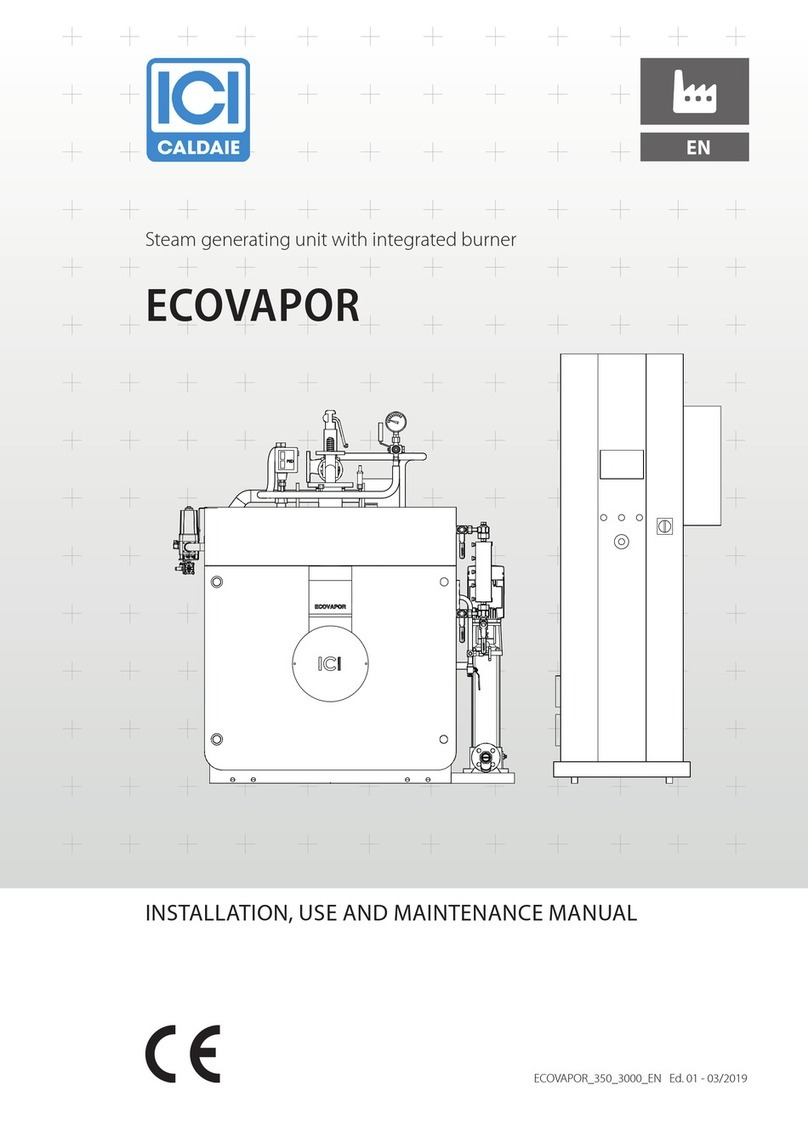
ICI Caldaie REX F 7 Service manual

ICI Caldaie

ICI Caldaie REX F 7 Service manual

ICI Caldaie CODEX GT Series User manual

ICI Caldaie

ICI Caldaie CODEX GT Series User manual

ICI Caldaie ECOVAPOR Series Service manual
ICI Caldaie

ICI Caldaie ECOVAPOR Series Service manual

ICI Caldaie FX N Series User manual

ICI Caldaie

ICI Caldaie FX N Series User manual

ICI Caldaie REX 140 Service manual

ICI Caldaie

ICI Caldaie REX 140 Service manual

ICI Caldaie BNX Series User manual

ICI Caldaie

ICI Caldaie BNX Series User manual

ICI Caldaie SIXEN User manual

ICI Caldaie

ICI Caldaie SIXEN User manual

ICI Caldaie MONOLITE JB Series User manual

ICI Caldaie

ICI Caldaie MONOLITE JB Series User manual

ICI Caldaie RIO 140 Datasheet

ICI Caldaie

ICI Caldaie RIO 140 Datasheet
ICI Caldaie SIXEN 350 Service manual

ICI Caldaie

ICI Caldaie SIXEN 350 Service manual

Popular Boiler manuals by other brands

IDEAL IMAX XTRA EL 320 user guide

IDEAL

IDEAL IMAX XTRA EL 320 user guide

UTICA BOILERS BC3D Installation, operation & maintenance manual

UTICA BOILERS

UTICA BOILERS BC3D Installation, operation & maintenance manual

Lochinvar SOLUTION 260000 Installation & service manual

Lochinvar

Lochinvar SOLUTION 260000 Installation & service manual

Weil-McLain EG 6 Series manual

Weil-McLain

Weil-McLain EG 6 Series manual

RBI LCD Series Installation & operation manual

RBI

RBI LCD Series Installation & operation manual

Baxi MainEco Combi 28 Installation and service manual

Baxi

Baxi MainEco Combi 28 Installation and service manual

Unical ALKON R 24 Installation and Servicing Manual

Unical

Unical ALKON R 24 Installation and Servicing Manual

Automatic Heating Gasogen Installation and Servicing Manual

Automatic Heating

Automatic Heating Gasogen Installation and Servicing Manual

Viessmann VITORADIAL 300-T Type VR3 Service instructions for contractors

Viessmann

Viessmann VITORADIAL 300-T Type VR3 Service instructions for contractors

Alpha GasSaver GS-1 Installation and servicing instructions

Alpha

Alpha GasSaver GS-1 Installation and servicing instructions

Baxi ROCA LAURA PLUS 28/28 Operating, cleaning and maintenance instructions for the user

Baxi

Baxi ROCA LAURA PLUS 28/28 Operating, cleaning and maintenance instructions for the user

Vaillant uniSTOR VIH SW GB 500 BES operating instructions

Vaillant

Vaillant uniSTOR VIH SW GB 500 BES operating instructions

Kärcher HWE 4000 Gas manual

Kärcher

Kärcher HWE 4000 Gas manual

Radijator BIO max 23.1 instruction manual

Radijator

Radijator BIO max 23.1 instruction manual

Granby BKC Installation, operation and maintenance manual

Granby

Granby BKC Installation, operation and maintenance manual

Brunner BSV 20 Instructions for use

Brunner

Brunner BSV 20 Instructions for use

Potterton 50e Installation and Servicing Manual

Potterton

Potterton 50e Installation and Servicing Manual

UTICA BOILERS TriFire Assembly instructions

UTICA BOILERS

UTICA BOILERS TriFire Assembly instructions

manuals.online logo
manuals.online logoBrands
  • About & Mission
  • Contact us
  • Privacy Policy
  • Terms and Conditions

Copyright 2025 Manuals.Online. All Rights Reserved.

REX_7_130_en_04 - 03/2020
EN
PRESSURISED STEEL BOILERS
REX 7 ÷ 130
INSTALLATION, USE AND MAINTENANCE MANUAL
Cooke Industries - Phone: +64 9 579 2185 Email: [email protected] Web: www.cookeindustries.co.nz
2
INDEX
SYMBOLS USED IN THE MANUAL
aDANGER
To indicate actions that, if not performed correctly, can result in injury of generic origin or may generate malfunction
or damage to the appliance; therefore require particular caution and adequate preparation.
dIT IS FORBIDDEN
To indicate operations that SHOULD NOT be performed.
mIMPORTANT
To indicate particularly useful information and important.
The illustrations and data presented are not binding. The company reserves the right to make without prior notice any changes it
deems appropriate for continuous improvement and constant updating.
General information
3 Introduction
3 Range
3 Compliance
3 Warranty
4 Warnings
4 Prohibitions
5 Hazards
5 Identification
6 Appliance description
6 Structure
7 Optional control panel
8 Dimensions and connections
9 Technical data
10 Technical data
11 Control panel
11 Burners
Boiler welding
12 Product receipt
13 Handling
13 Installation room
14 System cleaning
14 Hydraulic connections
14 Starting hydraulic circuit
15 Flue gas discharge and combustion air suction
16 Front door opening
17 Front door adjustment
17 Turbulator assembly
18 Insulating casing assembly
19 Bulb fastening
20 Burner assembly
20 Electrical connections
21 Water treatment
22 System filling and emptying
Use
23 Preliminary checks
23 Commissioning
23 Checks after commissioning
25 Stop periods
25 Decommissioning of old appliances
Maintenance
26 Boiler
27 Burner
28 Any anomalies and remedies
28 Environmental protection and disposal
29 Exploded views of drawings
Useful information and declarations
30 QR code
31 Declaration of Conformity
Notes
Cooke Industries - Phone: +64 9 579 2185 Email: [email protected] Web: www.cookeindustries.co.nz
General information 3
1 General information
INTRODUCTION
Dear Customer,
Thank you for having chosen an appliance of the series
REX
, a high quality and efficiency product, reliable and safe.
We recommend entrusting its maintenance to
Professionally Qualied Personnel
who, when necessary, uses original spare parts.
This manual contains important information and suggestions that must be observed for easier installation and best possible use
of the appliance.
mIMPORTANT
Failure to observe the instructions in this manual will void the warranty conditions.
RANGE
MODEL CODE
REX 7*
83801010
REX 8*
83801020
REX 9*
83802010
REX 10*
83802020
REX 12*
83802030
REX 15*
83803010
REX 20*
83803020
REX 25*
83804010
REX 30*
83805010
REX 35*
83806010
REX 40
83807010
REX 50
83808010
REX 62
83809010
REX 75
83810010
REX 85
83810020
REX 95
83811010
REX 100
83812010
REX 120
83812020
REX
130
83812030
* Product not compliant with the requirements set out in
the European regulations No. 811-813/2013 and therefore
not suitable for the installation on the EU territory for plant
rooms or produce domestic hot water.
The product can only be supplied for installations in non-EU
countries for any application
COMPLIANCE
REX
boilers comply with the following European Directives:
–European Regulation on Gas Equipment GAR 2016/426/EU
–Low Voltage Directive 2014/35/EU
–Electromagnetic Compatibility Directive 2014/30/EU
–Efficiency Directive 92/42/EEC
–Energy efficiency 
NOTE
The serial number is indicated on the boiler technical nameplate.
WARRANTY
The warranty conditions for boilers series
REX
are included in the CONSTRUCTION - WARRANTY CERTIFICATE supplied with the
product.
Cooke Industries - Phone: +64 9 579 2185 Email: [email protected] Web: www.cookeindustries.co.nz
General information4
WARNINGS
mIMPORTANT
–The appliance must be used for the purposes for which it has been expressly designed and any manufacturer’s liability shall
be excluded in case of damage to persons, animals or property due to insufficient maintenance or improper use.
–This manual is an integral part of the boiler and must be carefully read before installation and commissioning of the
appliance. Moreover, it must be carefully stored for subsequent consultations and must ALWAYS accompany the boiler
during its entire life-cycle (from installation to disposal). In case of damage or loss, request a copy from
ICI CALDAIE S.p.A.
Technical Assistance Service.
–The appliance is delivered in several separated packages. Upon receipt, check that the supply is intact and undamaged and
promptly contact the
ICI CALDAIE S.p.A.
if it does not correspond to the order.
–The installation of
REX
boilers must be performed by a Certified Body which, at the end of the operation, must provide
the owner with the declaration of conformity certifying that the installation has been correctly carried out, namely in
compliance with the Standards and the national and local Laws in force, and with the indications included in the instruction
manuals supplied by
ICI CALDAIE S.p.A.
.
–The maintenance of the appliance is a legislative obligation. The User must have it carried out by an Authorised Company
or by qualified personnel (maintenance technician) in compliance with the requirements of the local Standards in force.
–Ordinary and extraordinary maintenance must be carried out by qualified personnel in order to promptly detect any
damage to the boiler body under pressure and to the safety and control accessories.
–The boiler is used to heat water at a temperature lower than the boiling temperature at atmospheric pressure and must
be connected to a heating and/or domestic hot water production system, within the limits of its performance and power.
PROHIBITIONS
dIT IS FORBIDDEN
–Operate electrical devices or appliances such as switches, household appliances, etc. if you smell fuel or unburnt materials.
In this case:
-
ventilate the room by opening doors and windows
-
close the fuel shut-off device
-
ask the Technical Assistance Service or qualified personnel to intervene as soon as possible.
–Any technical or cleaning operation carried out before disconnecting the appliance from the power supply mains, by
positioning the system main switch and the control panel main switch to “OFF”.
–Modifying safety or adjustment devices without the boiler manufacturer’s authorisation and indications.
–Plug or dimensionally reduce the ventilation openings of the installation room. The ventilation openings are essential for
proper combustion.
–Exposing the boiler to atmospheric agents. It is not designed to operate outdoor and it does not feature automatic anti-
freeze systems.
–Leave flammable substances and containers in the room where the appliance is installed.
–Disperse the packaging material in the environment and leave it within the reach of children as it may be a potential source
of danger. It must be disposed of in accordance with the legislation in force.
Cooke Industries - Phone: +64 9 579 2185 Email: [email protected] Web: www.cookeindustries.co.nz
General information 5
HAZARDS
aDANGER
–In case of water leakages, disconnect the boiler from the power supply mains, close the water supply and contact, as soon
as possible, the Technical Assistance Service Authorised by
ICI CALDAIE S.p.A.
or qualified personnel.
–Sensing the presence of fuel in the thermal power plant, it is appropriate to follow the precautions below to avoid the risk
of explosions and fires:
-
do not smoke or cause sparks
-
do not turn on lights or electrical devices in general (mobile phones)
-
open doors and windows
-
close the fuel shut-off valve normally placed outside the thermal power plant
-
disconnect the power supply by means of the switch which is usually located outside of the plant room.
–During the normal operation, the appliance has hot parts, such as the channel and the flue gas box, which in case of
accidental contact without appropriate personal protection can cause severe burns.
–An incorrect adjustment of the closing door or an insufficient chimney draught can cause the presence of smoke inside
the heating plant room, leading to fatal intoxications due to carbon monoxide, which is by nature colourless and odourless.
Therefore, make sure that the boiler is correctly adjusted and installed and that the heating plant room features vents
compliant with the standards in force.
IDENTIFICATION
Each
REX
boiler can be identified through the construction plate (1) inside the envelope of the documents supplied with the
boiler, which includes technical/efficiency information such as:
–serial number or identification marking
–heat input in kW
–nominal thermal flow in kW
–types of fuels which can be used
–maximum operating pressure.
–CE marking
mIMPORTANT
The boiler installer
MUST
apply the construction plate, at the end of installation, in the front upper side of one of the
side panels of the cover, so that it can be easily identified and read. In case of loss, request a copy to the Technical
Assistance Service of
ICI CALDAIE S.p.A.
providing the serial number indicated in the CONSTRUCTION CERTIFICATE -
WARRANTY or the sale delivery note.
The appliance is also accompanied by
construction certicate
attesting the successful result of the hydraulic test.
mIMPORTANT
The installation must be performed in compliance with the local standards by
qualied personnel
, namely by
personnel with specific technical skills in the field of the heating system components. An incorrect installation may
cause damage to persons or property for which the manufacturer will not be liable.
During
commissioning
check the effectiveness of all adjustment and control devices in the control panel.
The
warranty
validity is subject to compliance with the instructions in this manual.
Cooke Industries - Phone: +64 9 579 2185 Email: [email protected] Web: www.cookeindustries.co.nz
General information6
APPLIANCE DESCRIPTION
High-efficiency
ICI CALDAIE S.p.A.
REX
steel boilers must be used for heating systems with water temperature within 60° and
100°C and/or in a system for domestic hot water production, within the limits of their performance and power.
The chosen control panel should be equipped with a safety thermostat with manual reset from 110°C.
They have been provided with cylindrical furnace with reverse flame closed at the back by a fully wet convex bottom, supported
by a stub and that can be coupled with forced draft burners.
Some of the main characteristics of the equipment are listed below:
–boiler body made in quality steel, made up by the front tube plate flanged towards the furnace with RSB process and by the
convex, instead of flat, rear plate, for better resistance to the internal pressure, with laser-cut holes
–cylindrical combustion chamber, with reverse flame, closed at the back with fully wet convex bottom, supported by a stub.
The flame runs through the central part, while the hot gases return peripherally to the front, partially wet, part to be conveyed
to the tube bundle
–EN10217-2 P235GH fire tubes, welded to the front and rear tube plates, equipped with helical turbulators
–rear smokebox made in steel metal sheet, consisting of a single piece that can be easily opened to inspect the fire tubes,
fastened by means of bolts, complete with chimney fitting and cleaning door
–containment tube bundle equipped with connections necessary for the system and the operating equipment, all welded
with approved processes carried out by qualified welders
–casing made with easily removable painted steel panels, that protect the insulation made with high-density fibreglass wool
mats
–front door made in steel metal sheet thermally insulated with ceramic fibre, fitted on hinges, that can be easily opened by
means of drilled ring nuts and with supplied lever.
STRUCTURE
1 2 12
N2
N3 N5 N5
N1
N4
789
4
N6
5
6
N7
10
3
N8
1
Control panel (accessory)
2
Front door
3
Flame inspection window
4
Rear smokebox
5
Flue gas drain fitting
6
Inspection door
7
Insulating casing
8
Door hinges
9
Burner (accessory)
10
Burner support flange
N1
Boiler flow fitting
N2
Boiler return fitting
N3
Instruments fitting
N4
System intake/drain fitting
N5
Safety valve(s) fitting
N6
Bulb-holder pockets
N7
Condensate drain fitting
N8
Control pocket
Cooke Industries - Phone: +64 9 579 2185 Email: [email protected] Web: www.cookeindustries.co.nz
General information 7
OPTIONAL CONTROL PANEL
The (optional) control panel, made of plastic with protection grade IP40, contains the regulation and safety instruments:
The upper casing of the control panel can rotate to access the terminal board and unwind the capillary tubes of thermostats and
thermometers.
The regulation thermostats have an operating range from 60°C to 100°C and can be calibrated by the user by means of the front
knob.
The safety thermostat has a fixed calibration of 110°C and a manual reset as required by the regulations.
The circulation pump enabling thermostat located inside the panel can be adjusted from 0°C to 90°C with a tool and is factory-set
to 50°C, its activation differential is 6°C. Thanks to this thermostat, the circulation pump remains stopped when the temperature
is lower than 50°C to avoid the hazardous flue gas condensation.
1 2
3
6
4
5
7
KEY
1
NETWORK LIGHT
2
BURNER SWITCH NO. 1
3
SYSTEM CIRCULATION PUMP SWITCH
4
BOILER THERMOMETER
5
LIMIT REGULATION THERMOSTAT
6
SAFETY THERMOSTAT
7
HIGH/LOW FLAME THERMOSTAT
WIRING DIAGRAM
See the diagram inside the electric panel.
Cooke Industries - Phone: +64 9 579 2185 Email: [email protected] Web: www.cookeindustries.co.nz
General information8
DIMENSIONS AND CONNECTIONS
175H1
H
H2
ØcH10
H6
Øb
P6
L2
L
P2
H4
P5P4P3
P
N2
N3 N5 N5
N1
N4
N7
N8
N6
Dimensions
Description
u.m.
REX
7* 8* 9*
10* 12* 15* 20* 25* 30* 35*
40 50 62 75 85 95
100 120 130
H
mm 1063
1063
1030 1030 1030 1080 1080 1080 1180 1180 1190 1380
1380
1510 1510 1510 1660 1660 1660
H1
mm
853 853 855 855 855 905 905 905
1005
1005 1015 1205 1205 1335 1335 1335 1485 1485 1485
H2
mm
415 415 415 415 415 440 440 440 490 490 500 610 610 675 675 675 750 750 750
H4
mm
912 912 912 912 912 962 962 962
1061 1061 1095 1285 1285 1417 1417 1417 1568 1568 1568
H6
mm
415 415 415 415 415 440 440 440 490 490 500 610 610 675 675 675 750 750 750
H10
mm
54,5 54,5 54,5 54,5 54,5 54,5 54,5 54,5 54,5 54,5 50 60 60 60 60 60 60 60 60
L
mm
756 756 756 756 756 806 806 806 906 906 946
1166 1166 1296 1296 1296 1446 1446 1446
L2
mm
700 700 700 700 700 750 750 750 850 850 890
1110 1110 1240 1240 1240 1390 1390 1390
P
mm
994 994
1119 1119 1119 1364 1364
1614
1614 1864 1872
1946
2235 2247 2247 2497 2477 2477 2477
P2
mm
630 630 755 755 755
1000
1000 1250 1250 1500 1502 1502 1792 1753 1753 2003
2003
2003 2003
P3
mm
413 413 513 513 513 513 513 513 523 523 600 663 663 704 704 704 703 703 703
P4
mm
240 240 265 265 265 475 475 725 700 980 850 850
1150 1100
1100
1200 1200 1200 1200
P5
mm
341 341 341 341 341 376 376 376 391 361 422 433 422 443 443 593 574 574 574
P6
mm
200-
250
200-
250
200-
250
200-
250
200-
250
200-
250
200-
250
200-
250
200-
250
200-
250
230-
280
270-
320
270-
320
270-
320
270-
320
270-
320
270-
320
270-
320
270-
320
Øb
mm
130 130 130 130 130 160 160 160 180 180 225 225 225 280 280 280 280 280 280
Øc
mm
200 200 200 200 200 250 250 250 250 250 250 300 300 350 350 350 400 400 400
For BIOGAS generators, add 40 mm to measurement P6
Attachments
Description
u.m.
REX
7* 8* 9*
10* 12* 15* 20* 25* 30* 35*
40 50 62 75 85 95
100 120 130
N1
DN/
in
50 50 50 50 50 50 50 50 65 65 80 80 80 100 100 100 125 125 125
N2
DN/
in
50 50 50 50 50 50 50 50 65 65 80 80 80 100 100 100 125 125 125
N1/N2 PN6666666666666666666
N3
DN/
in
1" 1" 1" 1" 1" 1" 1" 1" 1" 1" 1" 1" 1" 1" 1" 1" 1" 1" 1"
N4
DN/
in
1" 1" 1" 1" 1" 1" 1" 1" 1" 1" 1"
1”1/4 1”1/4 1”1/4 1”1/4 1”1/4 1”1/4 1”1/4 1”1/4
N5
DN/
in
----------
1”1/4
(1)
1”1/4 1”1/4 1”1/4 1”1/4 1”1/4 1”1/4 1”1/4 1”1/4
N6
DN/
in
1/2” 1/2” 1/2” 1/2” 1/2” 1/2” 1/2” 1/2” 1/2” 1/2” 1/2” 1/2” 1/2” 1/2” 1/2” 1/2” 1/2” 1/2” 1/2”
N7
DN/
in
1/2” 1/2” 1/2” 1/2” 1/2” 1/2” 1/2” 1/2” 1/2” 1/2” 1/2” 1/2” 1/2” 1/2” 1/2” 1/2” 1/2” 1/2” 1/2”
N8
DN/
in
1/2” 1/2” 1/2” 1/2” 1/2” 1/2” 1/2” 1/2” 1/2” 1/2” 1/2” 1/2” 1/2” 1/2” 1/2” 1/2” 1/2” 1/2” 1/2”
(1)One single connection
Cooke Industries - Phone: +64 9 579 2185 Email: [email protected] Web: www.cookeindustries.co.nz
General information 9
TECHNICAL DATA
DESCRIPTION u.m. REX
7* 8* 9* 10* 12* 15* 20* 25* 30* 35*
Effective rated
[1]
kW 70 80 90 100 120 150 200 250 300 350
Thermal capacity
kW 76 87 98 109 130 163 216 271 325 379
Efficiency at 100% (ref. P.C.I.)
[1]
% 92,11 91,95 91,84 91,74 92,31 92,02 92,59 92,25 92,31 92,35
Efficiency of 100% (stars)
[2]
% ** ** ** ** ** ** ** ** ** **
Max gas flow rate - G20
Stm3/h 8,04 9,21 10,37 11,53 13,76 17,25 22,86 28,68 34,39 40,11
Max gas flow rate - G30
kg/h 5,97 6,83 7,7 8,56 10,21 12,8 16,96 21,28 25,53 29,77
Max gas flow rate - G31
kg/h 5,9 6,76 7,61 8,47 10,1 12,66 16,78 21,05 25,25 29,44
Max flue gas flow rate
kg/h 119,8 137,23 154,51 171,8 205,02 257,03 340,61 427,33 512,41 597,64
Efficiency at 30% (ref. N.C.V.)
[1]
% 91,4 91,5 91,55 91,66 91,45 91,3 91,36 91,7 91,9 91,9
Pressure drops on exhaust side
mbar 0,8 1 0,8 1 1,1 1,2 1,9 2 2 2,9
Heat losses through the chimney
% 7,09 7,25 7,36 7,46 6,89 7,18 6,61 6,95 6,89 6,85
Heat losses through the casing
% 0,8 0,8 0,8 0,8 0,8 0,8 0,8 0,8 0,8 0,8
Heat losses with burner off
% 0,1 0,1 0,1 0,1 0,1 0,1 0,1 0,1 0,1 0,1
Flue gas temperature (Nom. output, air = 20°C) - GAS
°C 188 192 194 197 184 190 177 185 184 183
Flue gas temperature (Nom. output, air = 20°C) - OIL
°C 191 195 197 199 186 193 180 188 186 186
Flue gas temperature (Nom. output, air = 20°C) - FUEL
OIL
°C 191 194 197 199 186 193 180 187 186 185
CO
2
- GAS
% 10,5 10,5 10,5 10,5 10,5 10,5 10,5 10,5 10,5 10,5
CO
2
- OIL
% 13,5 13,5 13,5 13,5 13,5 13,5 13,5 13,5 13,5 13,5
CO
2
- FUEL OIL
% 14 14 14 14 14 14 14 14 14 14
Fluid pressure drop (ΔT=12K)
mbar 8 10 13 16 23 35 63 98 50 67
Rated pressure
bar5555555555
Total weight
Kg 216 216 258 258 258 346 346 431 475 542
Total capacity
l 105 105 123 123 123 172 172 220 300 356
Rated frequency ~ voltage
Volt ~
Hz 230 ~ 50 230 ~ 50 230 ~ 50 230 ~ 50 230 ~ 50 230 ~ 50 230 ~ 50 230 ~ 50 230 ~ 50 230 ~ 50
Electric protection rating
IP 40 40 40 40 40 40 40 40 40 40
Absorbed power
[3]
W 20 20 20 20 20 20 20 20 20 20
Allowed fuels
Methane - LPG - Diesel - Naphtha
[1] Average temperature 70°C.
[2] Efficiency Directive 92/42/EEC.
[3] With electronic control unit (circulator and burner excluded).
* Product not compliant with the requirements set out in the European regulations No. 811-813/2013 and therefore not suitable
for the installation on the EU territory for plant rooms or produce domestic hot water.
The product can only be supplied for installations in non-EU countries for any application
Cooke Industries - Phone: +64 9 579 2185 Email: [email protected] Web: www.cookeindustries.co.nz
General information10
TECHNICAL DATA
DESCRIPTION u.m. REX
40 50 62 75 85 95 100 120 130
Effective rated
[1]
kW 420 500 620 750 850 950 1020 1200 1300
Thermal capacity
kW 455 542 672 813 921 1030 1106 1301 1409
Efficiency at 100% (ref. P.C.I.)
[1]
% 92,38 92,25 92,26 92,25 92,29 92,23 92,22 92,24 92,26
Efficiency of 100% (stars)
[2]
%**--------
Max gas flow rate - G20
Stm3/h 48,11 57,35 71,11 86,03 97,46 108,99 117,04 137,67 149,1
Max gas flow rate - G30
kg/h 35,71 42,57 52,78 63,85 72,33 80,89 86,86 102,18 110,66
Max gas flow rate - G31
kg/h 35,32 42,11 52,21 63,16 71,55 80,02 85,92 101,07 109,46
Max flue gas flow rate
kg/h 716,84 854,52 1059,54 1281,85 1452,15 1623,95 1743,9 2051,28 2221,59
Efficiency at 30% (ref. N.C.V.)
[1]
% 91,8 91,9 91,8 91,8 91,8 91,7 91,9 91,8 91,7
Pressure drops on exhaust side
mbar 4,5 4,2 6,4 5,2 7,2 5,2 4 5,5 6,5
Heat losses through the chimney
% 6,82 6,95 6,94 6,95 6,91 6,97 6,98 6,96 6,94
Heat losses through the casing
% 0,8 0,8 0,8 0,8 0,8 0,8 0,8 0,8 0,8
Heat losses with burner off
% 0,1 0,1 0,1 0,1 0,1 0,1 0,1 0,1 0,1
Flue gas temperature (Nom. output, air = 20°C) - GAS
°C 182 185 185 185 184 185 186 185 185
Flue gas temperature (Nom. output, air = 20°C) - OIL
°C 185 188 188 188 187 188 189 188 188
Flue gas temperature (Nom. output, air = 20°C) - FUEL
OIL
°C 184 187 187 187 187 188 188 188 187
CO
2
- GAS
% 10,5 10,5 10,5 10,5 10,5 10,5 10,5 10,5 10,5
CO
2
- OIL
% 13,5 13,5 13,5 13,5 13,5 13,5 13,5 13,5 13,5
CO
2
- FUEL OIL
% 14 14 14 14 14 14 14 14 14
Fluid pressure drop (ΔT=12K)
mbar 42 60 92 55 71 89 42 58 68
Rated pressure
bar555555555
Total weight
Kg 584 853 963 1205 1205 1417 1843 1843 1843
Total capacity
l 360 540 645 855 855 950 1200 1200 1200
Rated frequency ~ voltage
Volt ~
Hz 230 ~ 50 230 ~ 50 230 ~ 50 230 ~ 50 230 ~ 50 230 ~ 50 230 ~ 50 230 ~ 50 230 ~ 50
Electric protection rating
IP 40 40 40 40 40 40 40 40 40
Absorbed power
[3]
W 20 20 20 20 20 20 20 20 20
Allowed fuels
Methane - LPG - Diesel - Naphtha
[1] Average temperature 70°C.
[2] Efficiency Directive 92/42/EEC.
[3] With electronic control unit (circulator and burner excluded).
Cooke Industries - Phone: +64 9 579 2185 Email: [email protected] Web: www.cookeindustries.co.nz