Icidu 200 MBPS User manual


CONTENTS
1 INTRODUCTION............................................................................................... 1
1.1 S y s t e m R e q u i r em e n t s ....................................................................................... 1
1.2 Package L is t ...................................................................................................... 1
2 SAFETY CAUTIONS .......................................................................................... 2
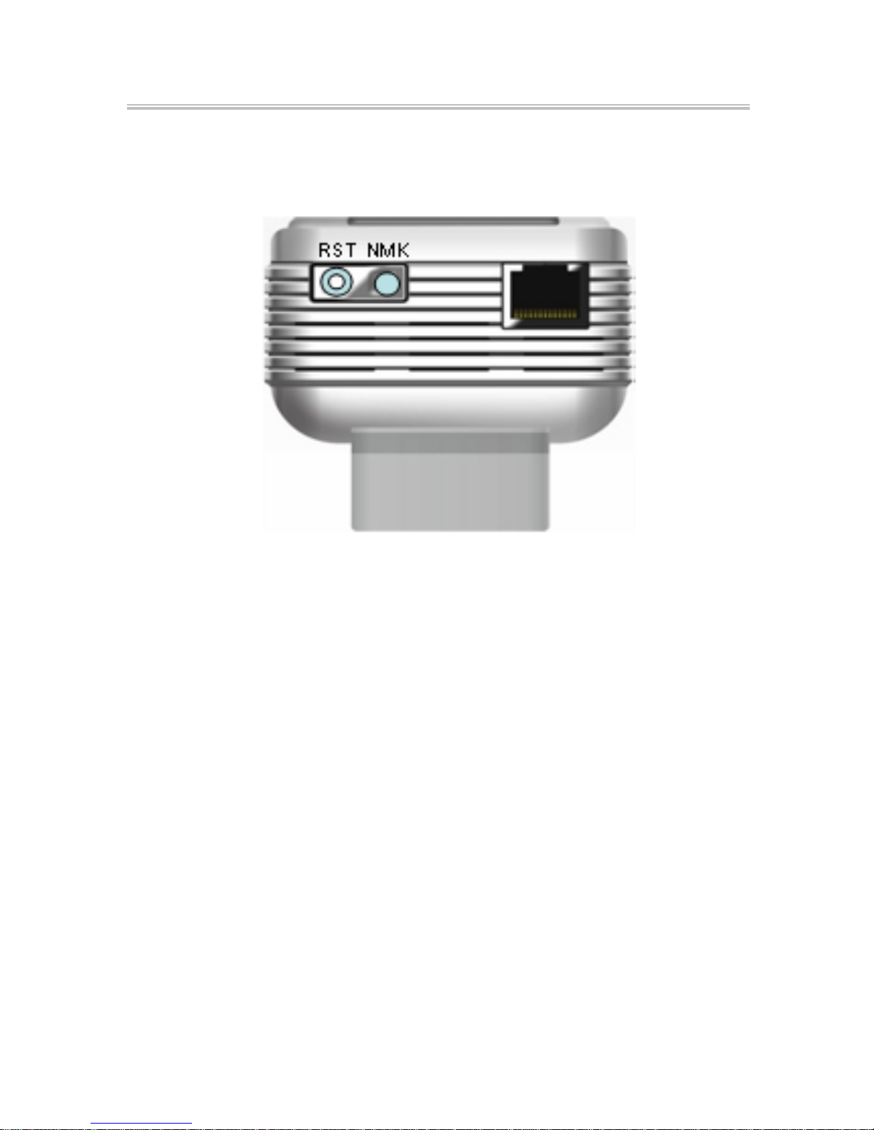
3 ADAPTER........................................................................................................ 2
3.1 Ethernet Interface.............................................................................................. 2
3.2 Buttons .............................................................................................................. 3
3.3 LEDs................................................................................................................... 3
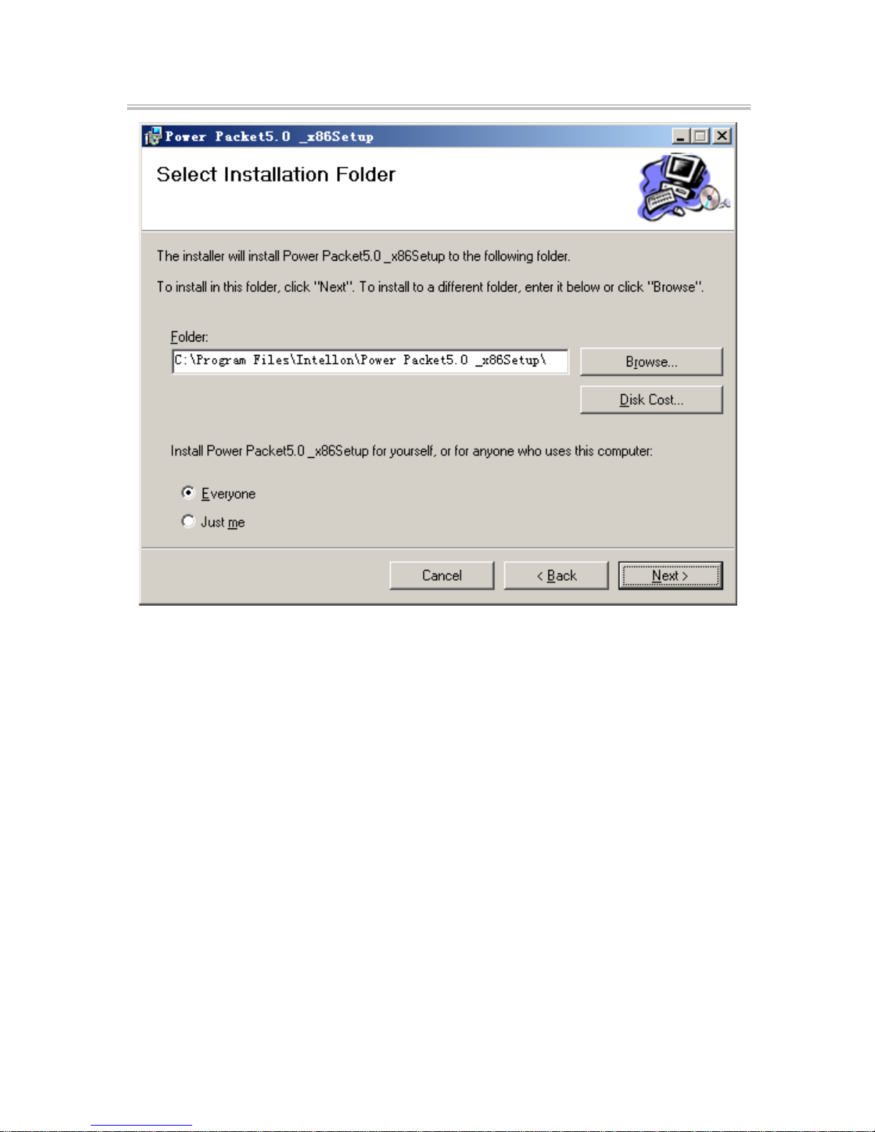
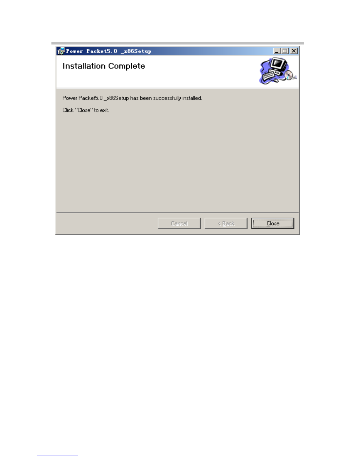
4 UTILITYINSTALLATION.................................................................................... 4
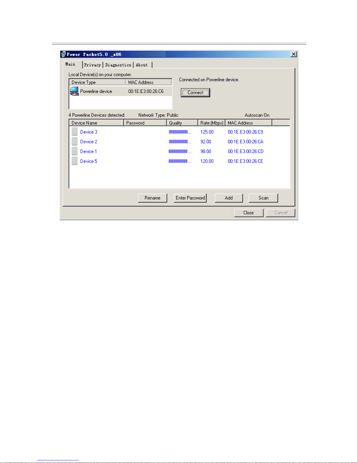
5 UTILITYSOFTWAREUSAGE.............................................................................. 7
5.1 Main Tab............................................................................................................ 7
5.2 Privacy Tab...................................................................................................... 11
5.3 Diagnostics Tab ............................................................................................... 12
5.4 About Tab ........................................................................................................ 14
6 NMK PUSHBUTTON USAGE............................................................................. 15
6.1 Forming a HomePlug AV Logical Network ....................................................... 15
6.2 Joining a Network ........................................................................................... 16
6.3 Leaving a Network........................................................................................... 17
APPENDIX A SPECIFICATIONS.................................................................................. 18
APPENDIX B ACRONYMSANDABBREVIATIONS......................................................... 20
APPENDIX C ABOUTQOS......................................................................................... 21

NI-707525HOMEPLUGADAPTERSTARTERKIT200MBPS
1
1 INTRODUCTION
The NI-707525 Homeplug Adapter utility program d e t e c t s 200 Mbps PLC-E t h e r n e t bridge
devices in the Homeplug network, measures data rate performance, ensures security of the
Homeplug network, and performs diagnostics.
1.1 SystemRequirements
OperatingSystem
Windows 2000, Windows XP, Windows V i s t a
32/64 bit, Windows 7?
CPU
Intel Pentium III or higher and clock rate faster
than 2.0 GHz are recommended.
RAM
At least 128 MB
ScreenResolution
Any resolution
FreeDiskSpace
At least 20 MB
Network Interface
At least one fast Ethernet (100 Mbps) network
interface card (NIC) and one Ethernet cord
1.2 PackageList
2 x Homeplug Adapter
1 x CD-ROM
2 x RJ45 Ethernet cable

NI-707525HOMEPLUGADAPTERSTARTERKIT200MBPS
2
2 SAFETYCAUTIONS
This device is used for connection to the AC Homeplug. Before using the device, read the
instructions carefully, in order to use the device correctly and safely. For installation
instructions, refer to the installation section of this guide.
Follow all the warnings and instructions marked on the product.
Before cleaning the device, unplug it from the wall outlet. U s e a dry c l ot h f o r
cleaning. Do not use liquid cleaners or aerosol cleaners.
Do not place the device near water.
Do not place the de v i c e near or over a radiator or heat register.
Do not use an extension cord between the device and the AC power source.
Only professional technicians should service the d e v i c e . Opening or removing covers
may result in exposure to dangerous voltage points or other risks.
Unplug the device from the wall outlet and refer to professional service personnel for
the following conditions:
–If liquid has been spilled into the product
–If the device has been exposed to rain or water
–If the device d o e s n o t o p e r a t e n o r m ally when following the operati on
i n s t r u c t i o n s
–If the device exhibits a distinct change in performance
3 ADAPTER
3.1 EthernetInterface
Use one end of a network cable to connect the Ethernet i n t e r f a c e . U s e t h e other end of the
cable to connect the Ethernet interface of the computer or another Ethernet-enabled
network device.

NI-707525HOMEPLUGADAPTERSTARTERKIT200MBPS
3
3.2 Buttons
Figure 3-1 Side panel
RST: Restore the factory defaults.
NMK: Set the membership state.
Pressing and holding the NMK button for more than 10 seconds
randomizes the NMK value.
Pressing and holding the NMK button for m o r e than 3.0 s e c onds
makes the adapter a member of the existing AVLN.
3.3 LEDs
There are 3 LEDs on the front panel to indicate the status of the adapter.
Power: Green. It is on when the adapter is powered on.
Ethernet: Green. It blinks to indicate activity over the Ethernet connection.
Data: Green. It blinks to indicate activity over the Homeplug connection.

NI-707525HOMEPLUGADAPTERSTARTERKIT200MBPS
4
CODED PHY RATE<30:RED
30<CODED PHY RATE<50:YELLOW
CODED PHY RATE>50:GREEN
The red light and the green light illuminate simultaneously and the indicator is in orange
when the device is in reset state.
Figure 3-2 Top view
4 UTILITYINSTALLATION
Before installing the utility, make sure that no other Homeplug utility is installed i n
the computer. If a n y other utility is installed, uninstall it and reboot the c o m p u t e r .
Insert the CD-ROM of the utility into the CD-R O M d r iv e r of the computer. Select
InstallUtility,follow the steps to install the utility program. No password or CD-K e y
is needed.

NI-707525HOMEPLUGADAPTERSTARTERKIT200MBPS
5
The page of utility installation is similar to the one shown in Figure 4-1. Click Next to
continue.
Figure 4-1 Setup wizard

NI-707525HOMEPLUGADAPTERSTARTERKIT200MBPS
6
Figure 4-2 Select installation folder

NI-707525HOMEPLUGADAPTERSTARTERKIT200MBPS
7
Figure 4-3 Installation complete
Click Closet o c om p l et e the installation.
5 UTILITYSOFTWAREUSAGE
5.1 MainTab
The Main screen provides a list of all Homeplug devices logically connected to the
computer when the utility is running.
The toppanelshows local HomePlug devices connected to the network interface c ard (NIC)
of the computer. Click Connect. The utility automatically scans the H o m e p l u g periodically
for other HomePlug devices when it is connected to the local device. If no local HomePlug
device is discovered, the status bar displays NOHOMEPLUGADAPTERSDETECTED.

NI-707525HOMEPLUGADAPTERSTARTERKIT200MBPS
8
Figure 5-1: Main tab information
The lower panel displays all the HomePlug remote devices, which are discovered in t h e
current logical network. The total number of remote devices connected in the same networ k
is displayed above the remote device panel. Network type (Publicor Private) depends on
the network status of the local device. Autoscans h o w s whether the autoscan function is
on. The following information is displayed for all devices that appear in the lower panel.
DeviceName
This column shows the default device name, which may be modified. To change the name,
click Renameor click the name and editing it in the list.
MACAddress
This column shows the MAC addresses of the remote devices.

NI-707525HOMEPLUGADAPTERSTARTERKIT200MBPS
9
Password
By default, this column is blank. Y o u can click EnterPasswordt o change it. The procedure
for setting the password of the device (required when creating a private network) is a s
follows:
Click the device name to select the device in the lower panel.
Click Enter Password. A dialog box appears, showing the device name and
password. See Figure 5-2.
Figure 5-2: Set device password
Click OK to verify the password. The password field accepts the device password in
a n y c a s e formats, with or without dash.
A c o n f i r m a tion box appears if the password is entered correctly. If a device is not found, a
message appears, providing suggestions to solve the common problems. This process
takes a f e w s e c o n d s .

NI-707525HOMEPLUGADAPTERSTARTERKIT200MBPS
10
Add
This button is used to add a remote device to the existing network by entering the device
password of the device. A dialog box appears. See Figure 5-3. You can enter a d e v i c e n a m e
and the password.
If the device is found and the password is entered correctly, a confirmation box appears . I f
a d e v ic e i s not found, a message appears, providing suggestions to solve the c o m m o n
problems.
Figure 5-3: Add remote device
Note: The device must be in the Homeplug (plugged in), so that you can
c o n f i r m the password and add the device to the network. If the device is not located,
a warning message appears.

NI-707525HOMEPLUGADAPTERSTARTERKIT200MBPS
1 1
Scan
This button is used to perform an immediate search for HomePlug devices connected to the
Homeplug network. By default, the utility automatically scans every a few seconds and
updates the displayed information.
5.2 PrivacyTab
In the Privacy screen, you can maintain security for the logical network and select the
device included in the network. See Figure 5-4.
All HomePlug devices are loaded using a default logical network (network name), which is
normally “HomePlug”. In the Privacy screen, you can m od if y a private network by
changing network names and passwords of devices.
Click Use Default or enter HomePlug a s t h e n e t w o r k n a m e , to reset to the HomePlug
network (Public).
Figure 5-4: Privacy screen

NI-707525HOMEPLUGADAPTERSTARTERKIT200MBPS
12
Note: If the network name changes to anything other than HomePlug, t h e
network type in the main screen is displayed a s Private.
SetLocalDeviceOnly
This button is used to change the network name and password of the local device. If a new
network password is entered, all the devices appeared in the Main panel prior to this are no
longer present in the new network, effectively making the local devices not to c o m m u n i c a t e
to the devices which are in the old logical network. Click SetLocalDiveOnly, the de v i c e s
previously set up with the same logical network (same network name) appears in the
device list.
SetAllDevices
This button is used to change the logical network of all devices that appear in the main
panel. If these d e v i c e s whose pa s s w o r d s have been entered for the same logical network, a
dialog box appears, indicating successful operation. For d ev i c e s w h o s e passwords are not
entered, a dialog b o x appears indicating operation failure.
5.3 DiagnosticsTab
The Diagnostics screen shows the system information and history of all remote devic es
appeared over a period of time. See Figure 5-5.
The Upper panel shows technical data concerning software and hardware on the host
computer that are used to communicate through HomePlug on the Homeplug network. It
includes the following:
Operating System Platform/Version
Host Network Name
User Name
MAC Address of all NICs (Network interface card) connected to the host
Identify versions of all Driver DLLs and Libraries used (NDIS) and
optionally

NI-707525HOMEPLUGADAPTERSTARTERKIT200MBPS
13
HomePlug chipset manufacturer name (Turbo Only devices)
MAC Firmware Version (Turbo Only devices)
MAC addresses of all devices connected locally to the host
Version of the Configuration Utility
Vendor name
Figure 5-5: Diagnostics screen
The Lower panel displays the hi s t o r y o f a l l r e m o t e d e v i c e s appeared onthecomputer over
a certain period of time. All the devices and the parameters of the devices on the Homeplug
network are listed. Devices that are active on the current logical networ k s h o w a t r a n s f e r
rate in the rate column. D e v i c e s on other networks, or devices that no longer exis t a r e
shownwitha“?”intherate column. The following remote device information is available
from the diagnostics screen:
Device Alias Name
MAC Address
Password

NI-707525HOMEPLUGADAPTERSTARTERKIT200MBPS
14
Device Last known rate
Device Last Known Network name
HomePlug chipset manufacturer name
Date device last seen on the network
MAC Firmware Version
The diagnostics information displayed can be saved to a text file for later use, or be printed
for reference for a technical support call. C l ic k deleteto delete the devices which are no
longer part of the network. A dialog window pops up with a confirmation message if t h e
user wants to delete a device whose password has been entered.
5.4 AboutTab
The About screen shows the software version and provides a html link to a w e b s it e , s u c h
as
www.PowerPacket.com
. Clicking the web address, it enters into the web site.
Figure 5-6: About screen

NI-707525HOMEPLUGADAPTERSTARTERKIT200MBPS
15
Preferences
The lower part of the panel displays options for turning the autoscan function on or off.
6 NMKPUSHBUTTONUSAGE
This section describes how to add new devices or remove old devices from a HomePlug AV
logical network (A V L N ) by using a NMK pushbutton.
Power LED status indicates the operation progress and r es u l t .
6.1 FormingaHomePlugAVLogicalNetwork
When two devices with different NMK values are connected to the same Homeplug, and the
user wants them to form a logical network.
1. Press the NMK button on device A for less than 3 seconds.
2. Press the NMK button on device B for less than 3 seconds. The button
on B must be pressed within 1 minute
3. W a i t f or t h e connection to complete.
The Power LED on both devices blinks evenly at 1-second intervals until the operation
succeeds or fails. If the connection succeeds, it illuminates steadily. If an error occurs, the
Power LED on the ‘adder’ blinks unevenly until the pushbutton on the ‘adder’ is pressed
again or the ‘joiner’ is reset by holding the pushbuttons down for more than 10 seconds.

NI-707525HOMEPLUGADAPTERSTARTERKIT200MBPS
16
A
PLC B
PLC C
PLC
A and B are not part of AVLN
A and B want to form an AVLN
Press NMK button on A less than 3 sec.
Press NMK button on B less than 3 sec.
A becomes “joiner”
B becomes “joiner”
B determines that A MAC address < B MAC address
B becomes “adder”
A accepts NMK from B
A
PLC
A
PLC B
PLC
B
PLC C
PLC
A and B are not part of AVLN
A and B want to form an AVLN
Press NMK button on A less than 3 sec.
Press NMK button on B less than 3 sec.
A becomes “joiner”
B becomes “joiner”
B determines that A MAC address < B MAC address
B becomes “adder”
A accepts NMK from B
Figure 6-1: Forming a HomePlug AV logical network
6.2 JoiningaNetwork
In this scenario a network exists, a new device, the ‘joiner’, wants to join the network.
Any device on the existing network can become the ‘adder’.
1. Press the pushbutton on the ‘joiner’ for at least 3 seconds.
2. Press the pushbutton on any network device for less than 3 seconds,
making it the ‘adder’. P l e as e press this pushbutton within 1 minute.
3. Wait for t h e connection to complete.
The Power LED on both devices blinks at 1-second intervals until the process succeeds or
fails. It illuminates steadily on success connection. If an error occurs, the Power LED on t h e
‘adder’ blinks unevenly until the pushbutton on the ‘adder’ is pressed again or the ‘joiner’ is
reset by pressing the pushbutton for more than 10 seconds.

NI-707525HOMEPLUGADAPTERSTARTERKIT200MBPS
17
A
PLC B
PLC C
PLC
A and B form an AVLN
C wants to join the AVLN
Press NMK button on B less than 3 sec.
Press NMK button on C less than 3 sec.
B becomes “adder”
C becomes “joiner”
C accepts NMK from B
A
PLC
A
PLC B
PLC
B
PLC C
PLC
A and B form an AVLN
C wants to join the AVLN
Press NMK button on B less than 3 sec.
Press NMK button on C less than 3 sec.
B becomes “adder”
C becomes “joiner”
C accepts NMK from B
Figure 6-2: Joining a network
6.3 LeavingaNetwork
A network exists. The user wants to remove one device, the ‘leaver’, from that network. The
user w a n t s to remove the device from service altogether or have it join another logical
network.
1. Press the pushbutton on the ‘leaver’ for at least 10 seconds. The device
resets and restarts with a random NMK.
2. Wait for t h e reset to complete.
The Power LED on the ‘leaver’ momentarily extinguishes during reset, blinks during restart,
then illuminates steadily. No error occurs.
The user can disconnect the device from the medium or join it to another logical network o n
the same medium when it is completed.

NI-707525HOMEPLUGADAPTERSTARTERKIT200MBPS
18
A
PLC B
PLC C
PLC
A, B and C form an AVLN
A wants to leave the AVLN
Press NMK button on A more than 10 sec.
A computes random NMK
C resets and restarts
A
PLC
A
PLC B
PLC
B
PLC C
PLC
A, B and C form an AVLN
A wants to leave the AVLN
Press NMK button on A more than 10 sec.
A computes random NMK
C resets and restarts
Figure 6-3: leaving a network
AppendixA Specifications
Chipset
Intellon INT6400
Protocol
Compliant with HomePlug AV 1.0
Co-existing with existing HomePlug 1.0
SystemSupport
Windows 98SE, Windows 2000, W i n d ows M E ,
Windows XP 32/64 bit and Windows Vista 3 2 /
64bit
PLC Rate
200 Mbps
ModulationBand
2MHz~30MHz
ModulationSchemes
Support QAM 1024/256/64/16/8, QPSK, B PS K
and ROBO
Encryption
128 AES
Other manuals for 200 MBPS
1
This manual suits for next models
1
Table of contents
Other Icidu Adapter manuals