3
4
5
1 6 FUNZIONAMENTO
Manuale d’Uso
TERMOSTATI ELETTRONICI DA PARETE
Leggere attentamente tutte le istruzioni
DIMENSIONI
SCHEMI DI COLLEGAMENTO
LEGENDA
INSTALLAZIONE
2
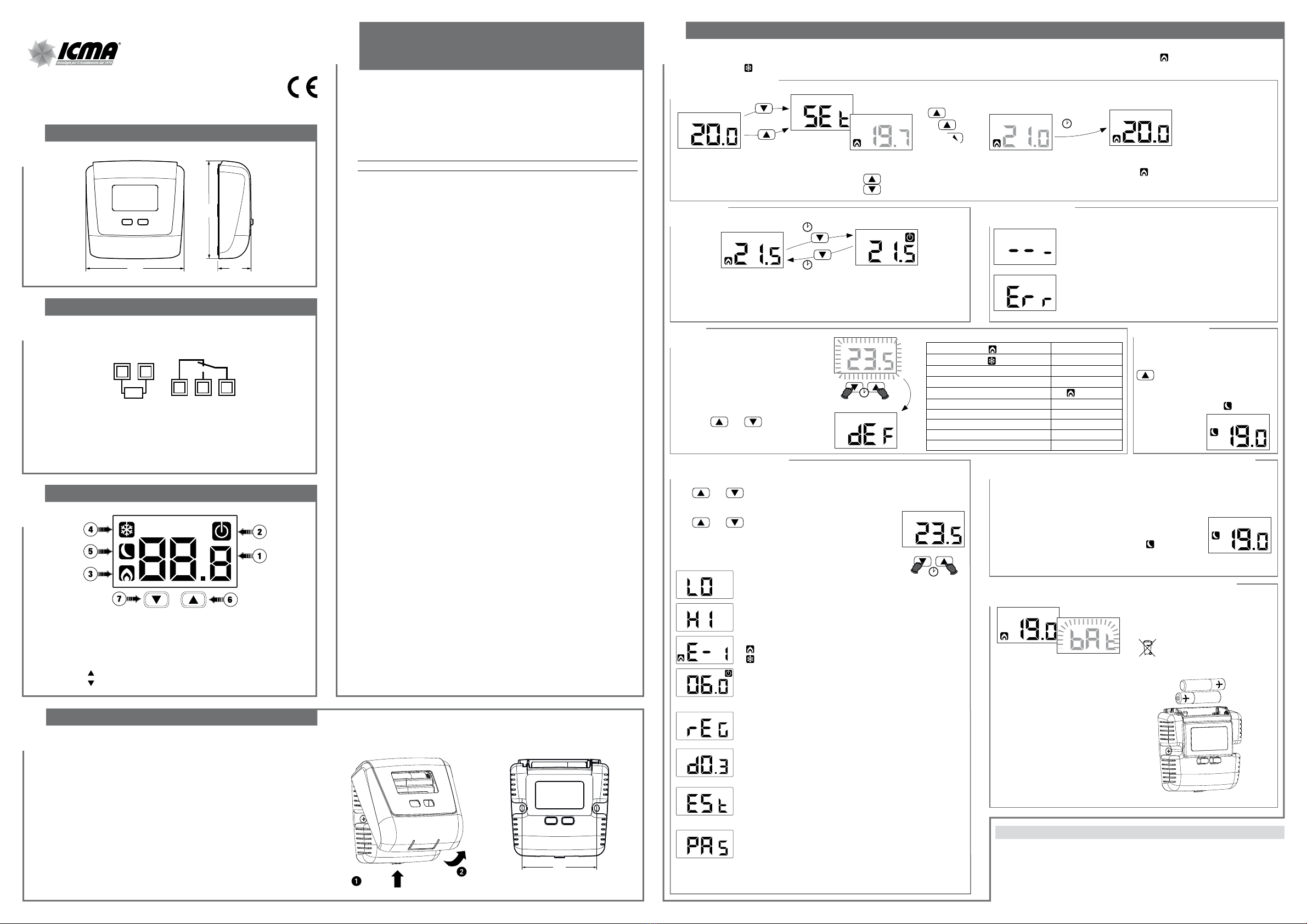
Programmazione avanzata
Modifica setpoint
Segnalazione batterie scariche
Messaggi di errore
Configurazione ingresso ausiliario
Sostituire le batterie appena possibile!
Smaltire le batterie negli ap-
positi contenitori della raccolta
differenziata.
Reset
Effettuare il reset per eliminare
le impostazioni effettuate e
ricaricare i valori di fabbrica.
Per effettuare il reset:
1rimuovere le batterie.
Attendere che il display si
spenga.
2Inserire le batterie. Durante il lampeggio
tenere premuti i tasti e finchè
a display compare la scritta DEf.
3 sec.
Valori di fabbrica
Setpoint riscaldamento 21 °C
Setpoint raffrescamento 25 °C
Minimo setpoint impostabile - L0 2 °C
Massimo setpoint impostabile - Xi 50 °C
Modalità di funzionamento (riscaldamento)
Temperatura di antigelo 6 °C
Tipo di regolazione On /Off
Differenziale 0,3 °C
Ingresso ausiliario DIG
Password - - - (disattivata)
La funzione “riduzione notturna” riduce
il setpoint impostato di 3 °C.
Tenere premuto per 3 secondi il tasto
per attivare (o disattivare, se già
attiva) la riduzione notturna.
Quando la riduzione notturna è attiva, a
display si accende il simbolo .
Riduzione notturna
INGRESSO
AUSILIARIO
COM
NANC
EST
84 28
84
Spegnimento
Normale funzionamento
Nota: In riscaldamento (inverno), lo strumento se spento, regola secondo la
temperatura di antigelo Toff, al fine di prevenire congelamenti dell’impianto.
Toff può assumere valori da 1 a 50°C oppure essere esclusa; in questo caso non è
garantita alcuna temperatura minima.
Si verifica nel caso di guasto sonda.
In questo caso la regolazione viene inibita e i contatti del relè
rimangono in posizione NC-COM
Si verifica per i seguenti valori di temperatura misurata:
t < 0°C
t >50°C
Modifica della temperatura
desiderata (setpoint),
per incrementare
per decrementare
Normale funzionamento
riscaldamento acceso ( )
oppure
3 sec.
3 sec.
19.8
19.9
...
3 sec.
V3IS00904-011
Termostato elettronico da parete a batterie adatto alla regolazione della tempe-
ratura sia in riscaldamento che in condizionamento.
Dispone di un ingresso ausiliario configurabile per il collegamento di una sonda
di temperatura o di un contatto esterno con il quale ridurre il setpoint di 3°C.
Svolge azioni di tipo 1B ed è destinato ad operare in ambienti con grado di in-
quinamento 2 e categoria di sovratensione III (EN 60730-1).
Codice Descrizione
88P4160199 Termostato a batterie con ingresso ausiliario
AVVERTENZE DI SICUREZZA
Durante l’installazione ed il funzionamento del prodotto è necessario rispettare
le seguenti indicazioni:
1) Lo strumento deve essere installato da persona qualificata rispettando
scrupolosamente gli schemi di collegamento.
2) Non alimentare o collegare lo strumento se qualche parte di esso risulta
danneggiata.
3) Dopo l’installazione deve essere garantita la inacessibilità ai morsetti di
collegamento senza l’uso di appositi utensili.
4) Lo strumento deve essere installato e messo in funzione in conformità con la
normativa vigente in materia di impianti elettrici.
5) Prima di accedere ai morsetti di collegamento verificare che i conduttori non
siano in tensione.
CARATTERISTICHE TECNICHE
• Alimentazione:
– 2 batterie alcaline da 1,5V (tipo AAA)
– autonomia: 1 anno
– indicazione batterie scariche
• Morsettiera:
– 3 morsetti per cavi da 1,5 mm2per relè di uscita 5A / 250 Vac
– 2 morsetti per cavi da 1,5 mm2per ingresso ausiliario (per collegare una sonda di
temperatura oppure un contatto esterno con il quale ridurre il setpoint di 3°C)
• Blocco tastiera con password
• Tipo di regolazione:
– on/off con differenziale impostabile (0,1 ÷ 1°C)
– proporzionale P8 con banda 0,8°C (-0,3 ÷ +0,5°C) e periodo 8 minuti
– proporzionale P15 con banda 1,5°C (-0,7 ÷ +0,8°C) e periodo 15 minuti
• Precisione di misura: ±0,5 °C
• Risoluzione temperatura misurata: 0,1°C
• Range impostazione setpoint: 2°C ÷ 50°C
• Temperatura di funzionamento: 0°C ÷ +50°C
• Temperatura di immagazzinamento: -10°C ÷ +65°C
• Umidità di funzionamento: 20÷90% non condensante
• Grado di protezione: IP40
• Isolamento: rinforzato tra parti accessibili (frontale) e tutti gli altri morsetti
Durante il normale funzionamento il termostato visualizza il valore della temperatura rilevata e l’eventuale intervento del relè è segnalato dal simbolo (modalità
riscaldamento) o dal simbolo (modalità condizionamento).
NORME DI RIFERIMENTO
La conformità alle Direttive Comunitarie
2014/35/UE (LVD)
2014/30/UE (EMCD)
è dichiarata in riferimento alle seguenti Norme Armonizzate:
• CEI EN 60730-2-9
Minimo setpoint impostabile - L0
E’ il valore minimo impostabile come setpoint.
Valori impostabili: 2 ÷ HI
Massimo setpoint impostabile - KI
E’ il valore massimo impostabile come setpoint.
Valori impostabili: L0 ÷ 50°C
Modalità di funzionamento - E-I
se collegato alla caldaia (riscaldamento)
se collegato a un impianto di condizionamento
Temperatura di antigelo - Toff - (solo in riscaldamento)
Temperatura minima mantenuta con strumento spento
(vedi riquadro «Spegnimento»).
Valori impostabili: 1 ÷ 50 °C oppure --- (funzione esclusa)
Tipo di regolazione - REG - (solo in riscaldamento)
0= on/off con differenziale impostabile
P8 = proporzionale con banda 0,8°C e periodo 8 minuti
P15 = proporzionale con banda 1,5°C e periodo 15 minuti
Differenziale - d0.3 - (solo per regolazione on/off)
Differenziale (o isteresi) per la regolazione della temperatura.
Valori impostabili: 0,1 ÷ 1°C
Configurazione ingresso - Est
- ^_ [ per il collegamento di una sonda di temperatura
- DIG per il collegamento di un contatto esterno per ridurre il
setpoint
(vedi riquadro “Configurazione ingresso ausiliario”)
Password per blocco tastiera - PAS
Impostare un valore tra 001 e 999 per attivare il blocco tastiera.
Impostare “---”per disattivare il blocco.
Se il blocco tastiera è attivo, premendo un tasto compare LoC
e viene richiesta la password. Se è inserita correttamente la
tastiera è sbloccata per i successivi 30 secondi.
88P4160199 dispone di un ingresso ausiliario configurabile per il collegamento in
alternativa di:
- una sonda di temperatura esterna remotabile. In questo caso per la
visualizzazione e la regolazione della temperatura viene utilizzato il valore
misurato dalla sonda esterna.
- un contatto esterno per la riduzione della temperatura
impostata. Con contatto esterno chiuso, il setpoint viene
ridotto di 3°C rispetto a quanto impostato e a display
compare il simbolo .
Per la configurazione dell’ingresso ausiliario, vedere “Programmazione avanzata” in
questo manuale.
Campo “Temperatura ambiente”
Campo “Spento”
Campo “Attivazione - Riscaldamento”
Campo “Attivazione - Condizionamento”
Campo “Riduzione notturna attiva”
Tasto “ ” Incrementa il campo selezionato - attivazione
riduzione notturna
Tasto “ ” Decrementa il campo selezionato
• Installare il termostato ad un’altezza di circa 1,5 m dal pavimento, al riparo
dall’irraggiamento diretto, lontano da porte, finestre, fonti di calore, posizioni
con eccesso o totale mancanza di aerazione.
• Rimuovere il guscio frontale agendo secondo la figura a lato.
• Effettuare i collegamenti rispettando gli schemi riportati in questo manuale.
• Inserire le batterie nell’apposito vano.
• Fissare lo strumento alla parete.
• Riposizionare il guscio frontale, accoppiando dapprima i dentini sul lato
superiore.
Per accedere al menù Programmazione avanzata tenere premuti contemporaneamente
per 3 secondi i tasti e finchè compare PR.
Vengono proposti in successione le voci del menù. Per ognuna viene
visualizzata la sigla identificativa seguita dal lampeggio del relativo
valore. Usare i tasti e per modificare il valore. Il passag-
gio al parametro successivo avviene trascorsi 3 secondi senza la
pressione di alcun tasto. Una volta impostati tutti i parametri viene
visualizzata la scritta END e il termostato torna al normale
funzionamento salvando le modifiche apportate.
60
Rimozione guscio frontale Vista interasse foratura
Sostituzione batterie
• Rimuovere il guscio frontale.
• Inserire le batterie nell'apposito vano
(attenzione alla polarità).
• Riposizionare il guscio frontale.
premere
ICMA S.p.a.
via Garavaglia, 4 - 20012 Cuggiono (MI) - ITALIA
Tel. +39 02 97249134 / +39 02 97249135 - Fax +39 02 97241550
12-2018
3 sec.