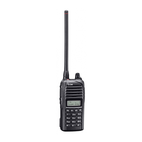
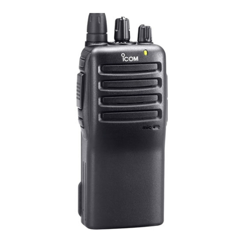
Icom IC-F620 Mounting instructions

CS-F620 Programming Software Manual
for
Icom IC-F620/F621TR

CS-F620TR Programming Software Manual (rev 1.0) -
i
Introduction .................................................................................................................... 1
Quick Start.................................................................................................................. 1
The Radio ................................................................................................................... 1
Typeface Conventions................................................................................................. 1
The Software............................................................................................................... 1
Software Compatibility ............................................................................................... 1
Trademark Notice........................................................................................................ 1
Installation .................................................................................................................. 1
Connecting Radio........................................................................................................ 2
Main Screen ................................................................................................................ 2
Quick Start!..................................................................................................................... 4
Programming Software in Detail ..................................................................................... 6
Main Menu ..................................................................................................................... 7
File Menu.................................................................................................................... 7
View Menu ................................................................................................................. 8
COM Port Menu..........................................................................................................8
Clone Menu ................................................................................................................ 9
Model Menu................................................................................................................ 9
Help Menu ................................................................................................................ 10
Toolbar ......................................................................................................................... 11
Tree Menu and Programming Screens........................................................................... 12
Special Notes on All Programming Screens............................................................... 12
The Red “X” ............................................................................................................. 12
Space Bar.................................................................................................................. 13
Right Click................................................................................................................ 13
The Word “System” .................................................................................................. 13
Defaults..................................................................................................................... 14
Key Functions and Programmable Keys .................................................................... 14
Tree Menu and Programming Screen Detail .................................................................. 15
Memory CH Folder....................................................................................................... 16
Operation Programming Screen Field Description Table ........................................... 17
PassPort Programming Screen....................................................................................... 19
PassPort Programming Screen Field Description Table ............................................. 19
PassPort Talk Group Setting Programming Sub-Screen............................................. 27
PassPort Talk Group Setting Programming Sub-Screen Field Description Table ....... 28
LTR Programming Screen............................................................................................. 30
LTR Programming Screen Field Description Table ................................................... 30
Repeater Setting Programming Sub-Screen ............................................................... 34
Repeater Setting Programming Sub-Screen Field Description Table.......................... 35
LTR Talk Group Setting Programming Sub-Screen................................................... 36
LTR Talk Group Setting Programming Sub-Screen Field Description Table ............. 36
Conv. Programming Screen........................................................................................... 38
Conventional Programming Screen Field Description Table...................................... 38
Recommended DTCS Codes ..................................................................................... 42
Seed Frequency Programming Screen ........................................................................... 43
CS-F620TR Programming Software Manual (rev 1.0) -
ii
Seed Frequency Programming Screen Field Description Table.................................. 43
ASID Text Programming Screen................................................................................... 45
ASID Text Programming Screen Field Description Table.......................................... 45
DTMF Autodial Folder ................................................................................................. 46
DTMF Encode Programming Screen............................................................................. 47
DTMF Encode Programming Screen Field Description Table ................................... 47
DTMF Decode Programming Screen............................................................................. 49
DTMF Decode Programming Screen Field Description Table ................................... 49
Common Folder ............................................................................................................ 51
Key & Display Assign Programming Screen................................................................. 52
Key & Display Programming Screen Field Description Table ................................... 52
Programmable Key Functions ................................................................................... 53
Programmable Key Functions Description Table....................................................... 53
Set Mode Programming Screen..................................................................................... 57
Set Mode Programming Screen Field Description Table............................................ 57
Common Programming Screen...................................................................................... 59
Common Programming Screen Field Description Table ............................................ 59
Timers Programming Screen......................................................................................... 62
Timers Programming Screen Field Description Table................................................ 62
Trunking Features Programming Screen........................................................................ 64
Trunking Features Programming Screen Field Description Table .............................. 64
Field Data Programming Screen Field Description Table .......................................... 66
Character Editor Programming Screen .......................................................................... 68
Appendix ...................................................................................................................... 70
APPENDIX A - RSSI Reference Chart (for “Min” and “Preferred” fields in the PassPort
Programming Screen).................................................................................................... 71
APPENDIX B - Suggested Radio Setups....................................................................... 72
PassPort ........................................................................................................................ 73
Key Assignments and Functions................................................................................ 73
Typical Functions and Conditions ............................................................................. 74
LTR Trunking............................................................................................................... 76
Key Assignments and Functions................................................................................ 76
Typical Functions and Conditions ............................................................................. 77
Conventional................................................................................................................. 78
Key Assignments and Functions................................................................................ 78
Typical Functions and Conditions ............................................................................. 79

CS-F620TR Programming Software Manual (rev 1.0) - Introduction
1
INTRODUCTION
QUICK START
If you’re looking to get started quickly, we can help. Read this brief introduction first and
we’ll quickly move you on to the “Quick Start!” section on page 4.
THE RADIO
Congratulations on the purchase of the Icom IC-F620/F621TR series radio for yourself or
your customer. The IC-F620/F621TR is a next generation, high performance multi-
format Trunking/Conventional radio sure to fit the broad needs of analog radio
consumers.
TYPEFACE CONVENTIONS
Throughout this manual certain typeface conventions are used for greater clarity, ease of
reading and emphasis.
•Key (radio button) references are in bold.
•Programming screen references are in italics.
•Specified selections in programming screen fields are quote delimited.
THE SOFTWARE
When programming the IC-F620/F621TR series radio, ensure that you are using the
software specifically designed for the LTR/PassPort version of the IC-600 series
transceivers (the software generally included with this .pdf file) - Icom part number CS-
F620TR. This cloning software is used to retrieve, edit and write radio configuration
information to the IC-F620/F621TR. It is also used as well as to retrieve and save radio
configuration information (from or to the programming computer) for archival purposes.
SOFTWARE COMPATIBILITY
This software is compatible with Microsoft Windows 98, 98SE, ME and XP.
TRADEMARK NOTICE
Windows is a registered trademark of the Microsoft Corporation in the U.S.A. and other
countries.
PassPort is a registered trademark of the Trident Datacom Technologies Inc.
LTR is a registered trademark of the EFJ Inc.
Windows 98/Me/XP are Microsoft trademarks.
INSTALLATION
Insert the installation CD into the programming computer. Using Explorer, navigate to
the root directory of the CD. There you will find two folders “CSF620TR” (the main
programming software) and “CSF620TRADJ” (used for adjusting the radio’s RF
functionality). Select the CSF620TR folder, execute “Setup” inside of it and follow the
on-screen directions. In the section titled “User Information” you must enter the software

CS-F620TR Programming Software Manual (rev 1.0) - Introduction
2
product ID (provided by Icom) before continuing. Once the software is installed, you can
start it by double clicking the CS-F620TR shortcut provided on the desktop or through
the start menu (navigate to “CS-F620TR”). At this point you can also install the
adjustment software by navigating to the CSF620TRADJ folder and executing “Setup”
there. This is only needed if you intend on performing radio alignment procedures and its
functionality is not discussed in this manual.
CONNECTING RADIO
Connect the 25 pin side of the OPC-1122 Connector to the programming laptop with the
25 to 9 pin serial cable provided in the programming cable kit. Connect the microphone
connector side of the OPC-1122 into the microphone jack of the radio. Power the radio
on.
MAIN SCREEN
From this screen, you can access all the functions of the software. The screen contains
five major components: the “Main Menu,” the “Toolbar,” the “Tree Menu” (with its
“Programming Screen Icons” and folders) and the “Programming Screen”.
•The Main Menu is used to provide access to all basic program functions not
associated with radio configuration.
Main Menu
Toolbar
Programming
Screen
Tree Menu
Programming
Screen Icons

CS-F620TR Programming Software Manual (rev 1.0) - Introduction
3
•The Toolbar provides quick access to commonly used functions.
•The Tree Menu contains various Programming Screen Icons and folders that provide
access to Programming Screens where you can read and edit detailed configuration
information.

CS-F620TR Programming Software Manual (rev 1.0) - Quick Start!
4
QUICK START!
This section is useful if you need abbreviated information on how to read, edit and write
programming information to a radio. This also serves as a useful overview of the
programming software in general.
•To access information concerning a radio (like ESN, serial number, transceiver
model, revision, comments and any installed option[s]) select (Clone Info.) from
the Toolbar.
•To read a radio press the (Clone Read) button on the Toolbar.
•To access configuration data stored in a file on the programming computers hard
drive, select on the Toolbar and use the dialog box to navigate to the correct data
file (usually with a “.icf” extension).
•To start a new programming instance, select “New” from the file menu.
•To select Programming Screens go to the Tree Menu. There you will see various
Programming Screen Icons and folders (folders contain icons that are broadly
related). Single clicking on an icon displays the programming screen associated with
that icon. To open a folder either double click on it or select the “plus” sign next to it.
If the sign is a “minus,” that signifies that the selected folder is already displaying its
contents. The LTR/PassPort icon is actually folder also. If it is collapsed, expand it to
see its contents.
•Once the correct programming screen is displayed, you can view or edit parameters.
On some programming screens, the parameters scroll horizontally off to the right, so
use the horizontal scroll bar at the base of the programming screen to view and edit
those parameters.

CS-F620TR Programming Software Manual (rev 1.0) - Quick Start!
5
•To enter or view Conventional system information, select “Conv.” from the Tree
Menu (in the Memory CH folder). The “Conv.” (Conventional)programming screen
will then appear. Enter the information required.
•You must enter data in the Text field first for each line item you enter before you
enter any other information. The program will force the cursor over to the Text field
if you try and enter information anywhere else.
•As you enter information concerning the first system, note the word “New” appears
on the next line. If you have another system you wish to enter after entering the first
one, enter it there.
•LTR and PassPort programming screens follow the same pattern as the preceding.
•Explore the other programming screens to set features as desired.
•To write to a radio press the (Clone Write) button. Yes, the icon looks like a
handheld and we’re most definitely programming a mobile here but it’ll work fine.
•To save configuration data to a file press the (Save) button. Use the dialog box
that to name the file and store it in the folder of your choice.
This concludes the Quick Start section.
Scroll this bar to the right to
view more parameters in this
programming screen.

CS-F620TR Programming Software Manual (rev 1.0) - Programming Software in Detail
6
PROGRAMMING SOFTWARE IN DETAIL

CS-F620TR Programming Software Manual (rev 1.0) - Main Menu
7
MAIN MENU
The Main Menu provides access to all basic program functions.
There are six Main Menu selections. Those selections and their sub-selections are
described as follows:
FILE MENU
Contains menu selections for operations concerning radio files, printing and quitting the
program.
File -> New: Create a new radio configuration file.
File -> Open…: Open an existing radio configuration file from the programming
computers hard drive, floppy drive, etc.
File -> Save: Save a radio configuration file to the programming computers hard drive,
floppy drive, etc.
File -> Save As…: Save a radio configuration file to the programming computers hard
drive, floppy drive, etc. under a name different from the currently open file.
File -> Print Current Sheet: Print current contents of programming screen. When selected,
a dialog box will appear. Select printer and other options from there.
File -> Print All: Print contents of all programming screens. When selected, a dialog box
will appear. Select printer and other options from there.

CS-F620TR Programming Software Manual (rev 1.0) - Main Menu
8
File -> Recent File Section: Displays the last 4 configuration files saved or opened.
File -> Exit. Quit the program.
VIEW MENU
Contains selections for customizing aspects of the programs appearance and
functionality.
View -> Font Size: Change the displayed font size in the programming screens. Goes
from 60% to 150%. While it maybe tempting to make the font size bigger for greater
legibility, doing so also has the side effect of making fewer columns visible in the
programming screens requiring more scrolling. Find the font size for you that offers the
best compromise between legibility and amount of displayed information.
View -> Toolbar: Select to display the toolbar or not. Not displaying it achieves a small
amount more of screen real estate at the expense of ease-of-use.
COM PORT MENU
Contains selections pertaining to COM port utilization.
COM Port -> COM 1, COM 2, COM 3, COM 4: Select the one you wish to use.
Selecting a port here will automatically deselect any other selected port including
“More…”
COM Port -> More…: Manually select a COM port number between 1 and 256.
Selecting a port here will automatically deselect any other selected port.

CS-F620TR Programming Software Manual (rev 1.0) - Main Menu
9
COM Port -> Normal: Use when radio read/write errors occur. Normal Speed is 9600
bps. Selecting this speed will automatically deselect High Speed. This is the default
selection.
COM Port -> High Speed: Use this selection unless you are having problems with radio
read/write errors. High Speed is 38400 bps. Selecting this speed will automatically
deselect Normal.
CLONE MENU
Contain selections for reading and writing to the IC-F620/F621TR series radio.
Clone -> Read <- TR: Read the configuration of a radio into the programming software.
Clone -> Write -> TR: Write the configuration of a radio from the programming software
to the radio.
Clone -> Information: Read basic information concerning the attached radio including
ESN, serial number, transceiver model, revision, comments and any installed option(s).
MODEL MENU
Allows selection amongst different radio models for the proper programming of the
attached radio. Ensure this selection matches the radio you have connected to the
program. Currently there is only one selection here.

CS-F620TR Programming Software Manual (rev 1.0) - Main Menu
10
Model -> LTR/PassPort: Only selection.
HELP MENU
Allows selection of help (this) document and general version and registration
information.
Help -> Contents: Select this help document.
Help -> About CS-F620TR: Displays information concerning current software version
and registration information as shown.

CS-F620TR Programming Software Manual (rev 1.0) - Toolbar
11
TOOLBAR
The Toolbar provides quick access to commonly used functions. Note: if you let your
mouse “hover” over a Toolbar button for about one second a tool tip will be displayed,
briefly describing the function of that button.
New Button: Create new radio configuration file.
Open Button: Access configuration data stored in a file on the programming
computer’s hard drive. When selected, use the dialog box to navigate to the correct data
file (usually with a “.icf” extension).
Save Button: Used to save configuration data to a file. When selected, use the dialog
box that opens to name the file and store it in the folder of your choice.
Clone Read: Used to read configuration information in an attached radio. If you get a
“No answer from transceiver” dialog box follow the onscreen recommendations.
Clone Write: Used to write configuration information to an attached radio. If you get
a “No answer from transceiver” dialog box follow the onscreen recommendations.
Clone Info: Read basic information concerning the attached radio including ESN,
serial number, transceiver model, revision, comments and any installed option(s).

CS-F620TR Programming Software Manual (rev 1.0) - Tree Menu and Programming Screens
12
TREE MENU AND PROGRAMMING SCREENS
From the Tree Menu you can select a variety of icons and folders. Selecting the
appropriate programming screen icon will display its associated programming screen to
the right. To open a folder in the Tree Menu either double click on it or select the “plus”
sign next to it. If the sign is a “minus” then that signifies that the selected folder is
already displaying its contents. Folders serve the purpose of keeping similar
programming screen icons grouped together. Collapsing a folder allows the user to de-
clutter the screen.
SPECIAL NOTES ON ALL PROGRAMMING SCREENS
THE RED “X”
The IC-F620/F621TR programming software has a special feature that allows for
fast diagnostics of configuration issues. If there is a configuration problem in any of the
programming screens, a will be displayed over its associated programming screen icon.
Additionally, if the programming screen that has an issue is selected, the program will
show specifically which area in the programming screen is having a problem. Look for
this when trying to diagnose configuration issues.
Tree Menu
Programming Screen
Programming
Screen Icon

CS-F620TR Programming Software Manual (rev 1.0) - Tree Menu and Programming Screens
13
TEXT DIALOG BOX
Many programming screens use a common text entry dialog box. The purpose of this box
is to help quickly and accurately enter text that the radio will display to the end user.
You can select the text you require by simply typing in the Text Entry field. You can also
enter text by double clicking on the characters listed in the Character Selection field or by
using your arrow keys to select a character and selecting the space bar to enter the
character in the Character Selection field.
As characters are entered in the Text Entry field they are displayed in the Text Results
field much as they would actually appear to the end user on the radio’s display. Study the
text you entered into the dialog box here to ensure that the results are satisfactory.
SPACE BAR
You can use the Space Bar of computer’s keyboard to advance through data choices in
programming screen fields that have drop down selections. This is a great way to speed
up data entry.
RIGHT CLICK
You can “right click” with your mouse on all of the fields of the programming screens.
Doing so usually brings up a small menu showing you the selections you have for that
field or row.
THE WORD “SYSTEM”
The PassPort, LTR and “Conv.” (Conventional) programming screens have a number of
rows prefaced with a number from the CH column. The guide avoids the word “channel”
in referring to these and will refer to every unique entry in each row as a “system” no
matter if it is Conventional, LTR or PassPort. For example if the “Conv.” programming
screen has 5 rows filled in then there are 5 “systems” in that programming screen. If the
PassPort programming screen has 3 rows filled in then there are 3 “systems” in that
programming screen. In this case there would be a total of 8 unique “systems” in the
radio. Of course, with the Operation programming screen, any of those systems can be
assigned to a given “channel” sequence on the Right Up/Down front panel control keys.
Text Entry Field
Text Results Field
Character
Selection Field

CS-F620TR Programming Software Manual (rev 1.0) - Tree Menu and Programming Screens
14
DEFAULTS
In many programming screens, you must generally make an entry in the Text field before
filling in other information. The defaults listed in the programming screen tables are the
defaults that you will see after this Text field has been entered.
KEY FUNCTIONS AND PROGRAMMABLE KEYS
The IC-F620/F621TR has a number of programmable keys on the radio and on the
optional HM-100TN DTMF microphone. Key Functions can be assigned to any of those
keys as described in the Key and Display Assign programming screen section starting on
page 52. In this document it assumed that when discussing something like “pressing the
Priority key” that a Priority key has been created by assigning the Priority key function
to a programmable key. That programmable key then inherits the name of the key
function.

CS-F620TR Programming Software Manual (rev 1.0) - Tree Menu and Programming Screen Detail
15
TREE MENU AND PROGRAMMING SCREEN DETAIL
LTR/PassPort: Selecting this icon will display description and revision information
in the programming screen. This icon is a folder also and opening it will display the next
level of icons and folders. Don’t let the LTR/PassPort description here confuse you, you
can still add, edit and delete Conventional system information from the icons inside this
folder.

CS-F620TR Programming Software Manual (rev 1.0) - Memory CH Folder
16
MEMORY CH FOLDER
Located in the main branch of the Tree Menu. This folder is used to group all
programming screen icons having to do with the configuration of each system in the IC-
F620/621TR. Use this to access and edit detailed information concerning each system in
the radio and setting system order on the channel selection buttons.

CS-F620TR Programming Software Manual (rev 1.0) - Memory CH Folder
17
OPERATION PROGRAMMING SCREEN
Operation Programming Screen Icon: Icon is located in Memory CH folder. This
programming screen allows the programmer to change the particular channel a system is
programmed to, delete a system all together and also to change the text displayed on the
radio for a particular system.
Note that to delete a system, you can right click on almost any field in the programming
screen and select “Delete” from the menu that appears. You can also reorder the channel
a system is in by right clicking on either the System Type or Text field and selecting
“Up” or “Down”. Note, you cannot add a system from here. To add a system, use the
programming screen icon of the mode you desire (also located in the Memory CH
folder).
OPERATION PROGRAMMING SCREEN FIELD DESCRIPTION TABLE
Field
Description
Default
Suggested
Settings
CH
The channel number and order of each system
in the radio.
No user entry.
No user entry.
System
Type
Type of system for the current channel number.
Potential entries here would be “Conv.,”
“LTR” or “PassPort”.
No user entry.
No user entry.
Text
Double click here to edit a text description for
this field (as described on page 13). You can
enter up to 10 characters for this field.
Whatever was
entered in the Text
field of the
PassPort, LTR or
“Conv.”
programming
screen when the
system was
created.
Set as needed.
Other manuals for IC-F620
3
This manual suits for next models
1
Table of contents
Other Icom Two-way Radio manuals

Icom
Icom IC-2200H Installation and operating instructions

Icom
Icom IC-F4TR User manual

Icom
Icom IC-775DSP Operating manual

Icom
Icom UT-111 User manual

Icom
Icom IC-F40GT User manual

Icom
Icom IC-A23 Administrator Guide

Icom
Icom IC-F3032T User manual

Icom
Icom IC-GM1600E User manual

Icom
Icom IC-F1500 User manual

Icom
Icom IC-GM1500 User manual