Icom IC-GM1600E User manual

INSTRUCTION MANUAL
iGM1600E
SURVIVAL CRAFT 2-WAY RADIO

i
PREFACE
Thank you for purchasing this Icom transceiver. The IC-
GM1600E survival craft 2-way radio is designed and built
with Icom’s state of the art technology and craftsmanship. With
proper care this product should provide you with years of trou-
ble-free operation.
IMPORTANT
READ ALL INSTRUCTIONS carefully and com-
pletely before using the transceiver.
SAVE THIS INSTRUCTION MANUAL—This
instruction manual contains important operating instructions
for the IC-GM1600E.
EXPLICIT DEFINITIONS
WORD DEFINITION
RWARNING!
RDANGER!
CAUTION
NOTE
Personal injury, fire hazard or electric shock
may occur.
Personal death, serious injury or an explo-
sion may occur.
If disregarded, inconvenience only. No risk
of personal injury, fire or electric shock.
Equipment damage may occur.
i
RECOMMENDATION
CLEAN THE TRANSCEIVER THOROUGHLY IN A BOWL
OF FRESH WATER after exposure to saltwater, and dry it
before operating. Otherwise, the transceiver’s keys,
switches, and controllers may become unusable, due to salt
crystallization, and/or the charging terminals of the battery
pack may corrode.
NOTE: If the transceiver’s waterproof protection appears
defective, carefully clean it with a soft, damp (fresh water)
cloth, then dry it before operating. The transceiver may
lose its waterproof protection if the case, jack cap, or con-
nector cover is cracked or broken, or the transceiver has
been dropped. Contact your Icom distributor or your dealer
for advice.
DISPOSAL
The crossed-out wheeled-bin symbol on your
product, literature, or packaging reminds you
that in the European Union, all electrical and
electronic products, batteries, and accumulators
(rechargeable batteries) must be taken to desig-
nated collection locations at the end of their
working life. Do not dispose of these products as unsorted
municipal waste. Dispose of them according to the laws in
your area.

ii
RECOMMENDATION ...................................................................... i
DISPOSAL ....................................................................................... i
PREFACE ........................................................................................ i
IMPORTANT .................................................................................... i
EXPLICIT DEFINITIONS ................................................................. i
PRECAUTION ............................................................................... iii
1 OPERATING RULES ����������������������������������������������������������������� 1
2 SUPPLIED ACCESSORIES AND ATTACHMENTS��������������� 2–3
■Supplied accessories .............................................................. 2
■Attachments ............................................................................ 2
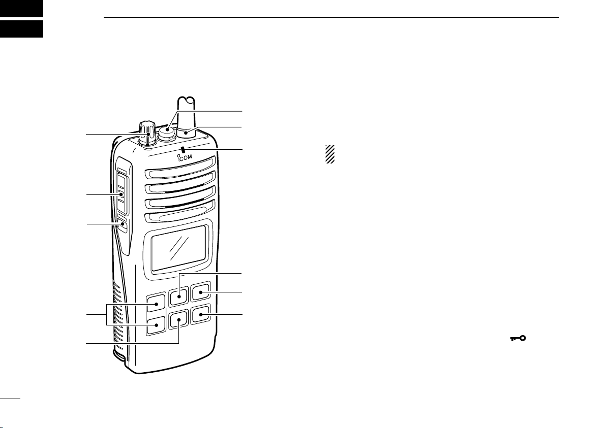
3 PANEL DESCRIPTION ���������������������������������������������������������� 4–6
■Front, top and side panels ....................................................... 4
■Function display ..................................................................... 5
4 BASIC OPERATION ������������������������������������������������������������ 7–10
■Channel selection ................................................................... 7
■Receiving and transmitting ..................................................... 8
■Call channel programming ..................................................... 9
■Adjusting the squelch level ..................................................... 9
■Lock function ........................................................................ 10
■Signal strength indicator function ......................................... 10
■Monitor function .................................................................... 10
■VOX function (FOR ON-BOARD USE ONLY) ....................... 10
5 SET MODE ������������������������������������������������������������������������ 11–14
■SET mode programming ...................................................... 11
■SET mode items ................................................................... 12
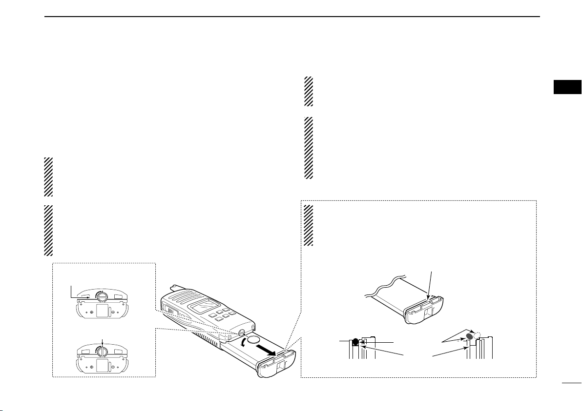
6 BP-234 LITHIUM BATTERY PACK ����������������������������������������� 15
7 BATTERY CHARGING (FOR ON-BOARD USE ONLY) ���� 16–19
■Important! ............................................................................. 16
■Battery cautions ................................................................... 16
■Battery charging ................................................................... 18
8 SURVIVAL CHANNEL LIST ���������������������������������������������������� 20
9 TROUBLESHOOTING ������������������������������������������������������������� 21
10 SPECIFICATIONS ������������������������������������������������������������������� 22
11 QUICK REFERENCE �������������������������������������������������������������� 23
12 OPTIONS ���������������������������������������������������������������������������� 24–25
TABLE OF CONTENTS 1
2
3
4
5
6
7
8
9
10
11
12
13
Icom is not responsible for the destruction or damage to the
Icom transceiver, if the malfunction is because of:
• Force majeure, including, but not limited to, res, earth-
quakes, storms, floods, lightnings, or other natural disas-
ters, disturbances, riots, war, or radioactive contamination.
• The use of Icom transceiver with any equipment that is not
manufactured or approved by Icom.

iii
RDANGER! NEVER short terminals (or charging
terminals) of the battery pack. Also, current may flow into
nearby metal objects such as a key, so be careful when
placing the battery packs (or the transceiver) in handbags,
and so on. Simply carrying with or placing near metal ob-
jects such as a key, and so on may cause shorting. This may
damage not only the battery pack, but also the transceiver.
RWARNING! NEVER connect the transceiver to an
AC outlet. This may pose a re hazard or result in an electric
shock.
RWARNING! NEVER
hold the transceiver so that the
antenna is closer than 2.5 cm from exposed parts of the body,
especially the face or eyes, while transmitting
. The transceiver
will perform best if the microphone is 5 to 10 cm away from
the lips and the transceiver is vertical.
NEVER connect the transceiver to a power source other
than the BP-234, BP-224* or BP-252. Such a connection will
ruin the transceiver.
* China version only
DO NOT use or place the transceiver in direct sunlight or
in areas with temperatures below –20°C or above +55°C.
KEEP the transciever out of the reach of children.
KEEP the transceiver at least 0.9 meters away from your
vessel’s magnetic navigation compass.
MAKE SURE
the flexible antenna and battery pack are
securely attached to the transceiver, and that the antenna and
battery pack are dry before attachment.
Exposing the inside
of the transceiver to water will result in serious damage to
the transceiver.
BE CAREFUL!
The IC-GM1600E employs waterproof
construction,
which corresponds to IMO resolution MSC.149
(77) (1 m depth for 5 minutes). However, once the trans-
ceiver has been dropped, waterproong cannot be guaran-
teed because of possible damage to the transceiver’s case
or the waterproof seal.
Icom, Icom Inc. and the Icom logo are registered trademarks of Icom Incorpo-
rated (Japan) in Japan, the United States, the United Kingdom, Germany,
France, Spain, Russia, Australia, New Zealand,and/or other countries.
NOTE:
• According to IMO resolution MSC. 149 (77) (adopted on 3
June 2003), the following regulation has been executed.
• “The equipment should have provisions for its attachment
to the clothing of the user and also be provided with a
wrist or neckstrap. For safety reasons, the strap should
include a suitable weak link to prevent the bearer from
being ensnared.”
• Instead of the handstrap, a neckstrap is supplied with the
equipment on or after 1st July, 2005.
PRECAUTION

11
1
OPERATING RULES
D Priorities
• Read all rules and regulations pertaining to priorities and
keep an up-to-date copy handy. Safety and distress calls
take priority over all others.
• You must monitor Channel 16 when you are not operating
on another channel.
• False or fraudulent distress calls are prohibited under law.
D Privacy
• Information overheard but not intended for you cannot law-
fully be used in any way.
• Indecent or profane language is prohibited.
D Transceiver licenses
(1) SHIP STATION LICENSE
When your craft is equipped with a VHF FM transceiver, you
must have a current transciever station license before using
the transceiver. It is unlawful to operate a ship station which
is not licensed.
Inquire through your dealer or the appropriate government
agency for a Ship-Radiotelephone license. This license in-
cludes the call sign which is your craft’s identification for
transceiver purposes.
(2) OPERATOR’S LICENSE
A restricted Radiotelephone Operator Permit is the license
most often held by small vessel transceiver operators when
a transceiver is not required for safety purposes.
The Restricted Radiotelephone Operator Permit must be
posted near the transceiver or be kept with the operator.
Only a licensed transceiver operator may operate a trans-
ceiver.
However, non-licensed individuals may talk over a trans-
ceiver if a licensed operator starts, supervises, ends the call
and makes the necessary log entries.
A current copy of the applicable government rules and regula-
tions is only required to be on hand for vessels in which a
transceiver is compulsory. However, even if you are not re-
quired to have these on hand it is your responsibility to be
thoroughly acquainted with all pertinent rules and regulations.
1

2
SUPPLIED ACCESSORIES AND ATTACHMENTS
2
■Supplied accessories
*Attach the ferrite core to the power adapter before charg-
ing.
See page 16 for details.
■Attachments
DNeckstrap
To attach the neckstrap, pass the
neckstrap through the loop on
the top of the transceiver as illus-
trated at right.
DBelt clip
Attach the belt clip to the transceiver as illustrated below.
Belt clip
(with 2 screws)
Battery packPower adapter
Neckstrap
Ferrite core
Battery charger
(with 2 screws)
*
Supplied screws

33
2
SUPPLIED ACCESSORIES AND ATTACHMENTS
DBattery pack
To remove the battery pack:
Turn the screw counterclockwise, then pull the battery pack
in the direction of the arrow as shown below.
To attach the battery pack:
Insert the battery pack in the IC-GM1600E completely, then
turn the screw clockwise.
NEVER remove or insert the battery pack when the
transceiver is wet or soiled. This may result water or dust
getting into the transceiver/the battery pack and may re
sult
in the transceiver being damaged.
NOTE: When removing or attaching the battery pack, use
a coin or flat-blade screwdriver to loosen or tighten the
bottom screw.
CAUTION:
When attaching or removing a battery pack, make sure
the rubber seal is set in the groove of the battery pack-
correctly. If the seal is not neatly in the groove it may be
damaged when attaching the battery pack.
If the seal is damaged, waterproong is not guaranteed.
OPEN
LOCK
Screw position
when removing battery
Screw position
when attaching battery
OPEN
LOCK
Make sure both the rubber seal (purple) is set to the groove
correctly and dust or else does not adhere to it.
Battery pack Battery pack
Rubber seal
Groove
Correct position Incorrect position
NOTE:
When attaching a battery pack, make sure dust or else does
not adhere to the rubber seal. If dust or else is on the seal
when attaching a battery pack, the water resistant may be
reduced.
2
NOTE: When the lock screw does not easily (feels tight),
check to ensure the battery pack is sufciently inserted to
the transceiver. DO NOT bang or cause high impact to
the battery pack, as this may damage the battery pack/or
the transceiver.

4
PANEL DESCRIPTION
3
■Front, top and side panels
qVOLUME CONTROL [VOL]
Turns power ON and adjusts the audio level.
wMICROPHONE CONNECTOR [MIC/SP]
Connects the optional external microphone.
NOTE: Attach the [MIC/SP] cap when the optional
speaker-microphone is not used.
eANTENNA
Fixed type.
rTRANSMIT/RECEIVE INDICATOR
Lights green while receiving a signal or when the squelch
is open, and lights red while transmitting (lights orange
while VOX function is used).
tCALL CHANNEL SWITCH [CALL]
➥ Selects the call channel when pushed. (p. 7)
➥Push for 3 seconds to enter call channel programming
condition. (p. 9)
yCHANNEL SWITCH [CH]
Push to return the previous condition when priority chan-
nel or call channel is selected. (p. 7)
uTRANSMIT POWER/LOCK SWITCH [Hi/Lo• ]
➥Selects high or low power when pushed. (p. 8)
➥Toggles the lock function ON/OFF when pushed for
1 second. (p. 10)
MIC
/SP
o
q
!1
!0
i
y
t
u
e
r
w

55
3
PANEL DESCRIPTION
iCHANNEL 16 SWITCH [16]
Selects Channel 16 when pushed. (p. 7)
oCHANNEL UP/DOWN SWITCHES [Y]/[Z]
➥Selects an operating channel. (pp. 7–8)
➥Selects the SET mode condition of the item. (p. 11)
➥ Selects the SET mode item when pushed with [SQL•
MONI]. (p. 11)
!0 SQUELCH SWITCH [SQL•MONI]
➥Push this switch, then adjust the squelch level with
[Y]/[Z]. (p. 9)
➥Manually opens the squelch for monitoring the channel
while pushed and held. (p. 10)
➥While pushing this switch, turn power ON to enter the
set mode. (p. 11)
!1 PTT SWITCH [PTT]
Hold down to transmit; release to receive.
■Function display
q e r tw
y
u
i
!0
o
q SIGNAL STRENGTH INDICATOR (pp. 10, 13)
Shows the relative signal strength while receiving signals.
w TRANSMIT POWER INDICATOR (p. 8)
➥ “LOW” appears when low power is selected.
➥No indication appears when high power is selected.
e SQUELCH LEVEL INDICATOR (p. 9)
Show the squelch level.
r MONITOR INDICATOR (p. 10)
Appears when the monitor function is activated.
3

6
3PANEL DESCRIPTION
t BATTERY INDICATOR
Indicates remaining battery power.
y VOX INDICATOR
“VOX” appears when the VOX function is used. (p. 10)
u SET MODE ITEM READOUT
Indicates the SET mode item while in the SET mode.
(p. 11)
i LOCK INDICATOR
Appears when the lock function is activated. (p. 10)
oCHANNEL NUMBER READOUT
➥Indicates the selected operating channel number.
➥In SET mode, indicates the selected condition.
!0 CALL CHANNEL INDICATOR
Appears when the call channel is selected. (p. 7)
NOTE: The backlight is ON at all times.

77
4
BASIC OPERATION
3
4
■Channel selection
DChannel 16
Channel 16 (Distress channel) is used for establishing initial
contact with another station and for emergency communica-
tions. While standing by, you must monitor Channel 16.
qPush [16] to select Channel 16.
w
Push [CH] to return to the condition before selecting Chan-
nel 16, or push [Y]/[Z] to select the operating channel.
DCall channel
The call channels can be re-programmed (p. 9) and may be
used to store your most often used channels for quick recall.
qPush [CALL] to select the call channel.
• “CALL” and the call channel number appear.
• Call channel can be re-programmed. See the “Call channel
programming” on p. 9 for details.
wPush [CH] to return to the condition before selecting the
call channel, or push [Y]/[Z] to select the operating chan-
nel.

8
4BASIC OPERATION
■Receiving and transmitting
CAUTION: Transmitting without an antenna may damage
the transceiver.
q Rotate [VOL] clockwise to turn power ON.
w Set the volume and squelch level.
➥ Push [SQL•MONI], and push [Z] to open the squelch.
➥ Push [SQL•MONI] to stop “SQL” indicator blinking, then
rotate [VOL] to set the volume level.
➥ Push [SQL•MONI], and push [Y]/[Z] to set the squelch
level.
e Push [Y]/[Z] to select the desired channel.
- When receiving a signal, the [TRANSMIT/RECEIVE] indicator
lights green while audio is emitted from the speaker.
- Further adjustment of [VOL] may be necessary at this point.
r Push [Hi/Lo• ] to select the output power if necessary.
- “LOW” appears when low power is selected; no indication when
high power is selected.
- Choose low power to conserve battery power, choose high
power for longer distance communications.
t Hold down [PTT] to transmit, then speak into the
microphone.
- The [TRANSMIT/RECEIVE] indicator lights red while
transmitting.
y Release [PTT] to receive.
IMPORTANT: To maximize the readability of your trans-
mitted signal, pause a few seconds after pushing [PTT],
hold the microphone 5 to 10 cm from your mouth and
speak into the microphone at a normal voice level.
MIC
/SP
q Power ON
w Set volume
r Set output power
Speaker
t Push to transmit
y Release to receive
w Set the squelch level
e Set channel
w Set the squelch level
Microphone

99
4
BASIC OPERATION
4
■Call channel programming
The call channel switch is used to select the default channel,
however, you can program your most often-used channel for
quick recall.
qPush [CALL] to select the call chan-
nel.
• “CALL” and call channel number
appear.
wPush [CALL] again for 3 seconds
(until a long beep changes to 2
short beeps) to enter call channel
programming condition.
•
Call channel number to be pro
grammed
flashes.
ePush [Y]/[Z] to select the desired
channel.
rPush [CALL] to program the dis-
played channel as the call channel.
• The call channel number stop ashing.
■Adjusting the squelch level
To adjust the IC-GM1600E’s squelch level, use the [Y]/[Z]
keys as desired below. In order to receive signals properly, the
squelch must be adjusted to the proper level.
q Push [SQL•MONI], then adjust the squelch level with [Y]/[Z].
- “SQL” indicator starts blinking.
- There are 11 squelch levels to choose from: OP is completely
open; 10 is tight squelch; 1 is loose squelch level.
- When no switch is pushed for 5 seconds, the transceiver re-
turns to normal condition.
w Push [SQL•MONI] again to return to normal condition.
Blinks during the squelch
level adjutment.
Indicates the
squelch level.
Push

10
4BASIC OPERATION
■Lock function
This function electronically locks all switches (except for
[PTT], [SQL•MONI] and [Hi/Lo• ]) to prevent accidental
channel changes and function access.
➥ Push [Hi/Lo• ] for 1 second to turn the lock function
ON and OFF.
■Signal strength indicator
function
The received signal strength level is indicated by number of
bars as below.
This indicator can be hidden by using the set mode (p. 13) if
deired.
■Monitor function
The monitor function releases the noise squelch mute to
check the volume level. See p. 12 for details of the monitor
switch action.
➥
Push [SQL•MONI] for 1 second to activate the monitor func-
tion.
• “ ” appears and audio is emitted.
■VOX function
(FOR ON-BOARD USE ONLY)
The VOX function (voice operated transmission) starts trans-
mission without pushing [PTT] when you speak into micro-
phone, then automatically returns to receive when you stop
speaking (hands-free operation becomes possible).
NOTE: An optional headset and optional headset adapter is
required for the VOX operation.
➥ Hold down [SQL•MONI], then push [Hi/Lo• ] to turn the
VOX function ON/OFF while connecting the optional head-
set and optional headset adapter to the [MIC/SP] connec-
tor.
• “VOX” appears on the LCD while the VOX function turns ON.
• The “VOX gain” and “VOX delay” can be set on the SET mode.
(p. 14)
Indication
Strong Middle Weak No signal or
very weak
Signal
strength
Appears while the
lock function is used.
Push
for 1 second

1111
5
SET MODE
4
5
■SET mode programming
SET mode is used to change the condition of 9 transceiver
functions: Beep tone function, Monitor switch action, LCD
contrast selection, Self check function, Battery voltage indi-
cator, Signal strength indicator, Squelch sensitivity function,
VOX gain and VOX delay.
D
SET mode operation
q
Turn power OFF
.
w While pushing [SQL•MONI], turn power ON to enter the
SET mode.
• “bp” (Beep tone function setting) appears.
e Push [SQL•MONI] or [SQL•MONI] and [Y]/[Z] to select the
desired item, if necessary.
r Push [Y]/[Z] to select the desired condition of the item.
t Push [16] to exit the SET mode.
DSET MODE ITEMS The displays show the default settings, and the selected item is displayed in the dotted circle.

12
5SET MODE
■SET mode items
DBeep tone function “bP”
You can select silent operation by turning the beep tones
OFF, or you can have 2 types of conrmation beeps sound
at the push of a switch. When “ON” is selected, a xed beep
(Pi) sounds, and when “US” is selected, the preset beeps
(e.g. do, re, mi) sound.
• Beep tone synchronises with the volume level.
• The beeps sound during call channel programming even if this
function is turned OFF.
DMonitor switch action “Sq”
The monitor switch action cuts off the squelch function tem-
porarily. This switch action contains PUSH (Pu) or HOLD
(Ho) settings as shown below.
• Pu (PUSH): After pushing [SQL•MONI] for 1 second, the squelch
opens and emits audio. The squelch is held open while
continuously pushing and holding [SQL•MONI]. (de-
fault)
• Ho (HOLD): After pushing [SQL•MONI] for 1 second, the squelch
opens and emits audio even [SQL•MONI] is released.
To close the squelch, push any switch.
DLCD contrast selection “LC”
The contrast of the LCD can be adjusted from 4 levels.
•
1 (bright)–4 (dark); 3 (default)
Push
Beep tone ON (default) Beep tone OFF
Push
Push setting (default) Hold setting

1313
5
SET MODE
5
DSelf check function “SC”
The self check function checks the transceiver conditions by
itself, and informs you in case a problem is found. Self check
automatically and quickly runs through its diagnostic steps
each time the transceiver is turned ON. Afterwards, the
transceiver switches to normal operation mode.
• Temperature : Outside of –35°C to +80°C (approximate)
• Connected battery voltage
When error messages as shown below are displayed, see
troubleshooting for advice. (p. 21)
DBattery voltage indicator “bt”
This function controls display or non-display settings of the
connected battery pack’s voltage when the power is ON.
•
The voltage of the connected battery pack is displayed for 2 sec-
onds after power is turned ON.
DSignal strength indicator “Sl”
The signal strength indicator displays received signal
strength as “S-meter”. This function is convenient to check
the signal strength visually.
•
The strength is displayed at 4 steps.
• The antenna
mark and 3 bars appear
when receiving
strong
signals.
• The antenna mark only appears when receiving no signal.
Push
Self check OFF (default) Self check ON
Temperature error Battery voltage error
Push
Battery voltage
indication OFF
(default)
Battery voltage
indication ON
Push
Signal strength
indication OFF
(default)
Signal strength
indication ON

14
DSquelch sensitivity function “SS”
When this function is turned ON, blocking against noise is im-
proved. Therefore the squelch is not easily affected by noise.
DVOX gain “ga”
(Available for on-board use only)
Adjusts the VOX gain (from 1 to 6) to level when speaking
with the optional headset.
• In case of setting to 1, the VOX gain sets to sharpening.
• In case of setting to 6, the VOX gain sets to dulling.
DVOX delay “dL”
(Available for on-board use only)
Sets the VOX delay timer (0.5 to 3.0 seconds in 0.5 second
steps) that keeps on transmitting after you stop speaking.
• In case of setting to 0.5, the VOX delay sets to short.
• In case of setting to 3.0, the VOX delay sets to long.
Push
Squelch sensitivity OFF
(default)
Squelch sensitivity ON
SET MODE LIST
*default setting
Function Indication Switch
Beep tone function “bP” OFF/ON*/US
Monitor switch action “Sq” Push*/Hold
LCD contrast selection “LC” 1/2/3*/4
Self check function “SC” OFF*/ON
Battery voltage indicator “bt” OFF*/ON
Signal strength indicator “SI” OFF*/ON
Squelch sensitivity “SS” OFF*/ON
VOX gain “ga” 1/2/3*/4/5/6
VOX delay “dL”
0.5/1.0*/1.5/2.0/2.5/3.0
Push
VOX gain 3 (default) VOX gain 6
Push
VOX delay 1.0 (default) VOX delay 3.0
5SET MODE

15
5
6
16
15
14
13
12
11
10
9
8
7
4
3
2
1
6
BP-234 LITHIUM BATTERY PACK
The IC-GM1600E is certified as a GMDSS survival craft
portable transceiver ONLY when used with the BP-234 Lith-
ium battery pack.
For reasons of shelf-life and air cargo regulations, the BP-234
Lithium battery pack is listed as an option but its use in
GMDSS applications is mandatory.
Always ensure the sufficient BP-234 Lithium battery packs
are available for use in any distress situation and their
sealed bag are intact and that their shelf-life has not expired.
The BP-234 Lithium battery pack is not rechargeable and
must be replaced after any use.
The following precautions must be observed.
• RDANGER! KEEP battery packs away from fire. Fire or heat
may cause them to rupture or explode. Dispose of an used battery
pack according to local ordinances and/or regulations.
•
DO NOT short-circuit the BP-234 Lithium battery pack. Metal con-
tact (such as paper clip, another battery, and so on) across the
battery contacts can result in a sustained high rate discharge,
which could damage the battery, void the warranty and create a
burn or a re hazard.
•
NEVER expose of the BP-234 Lithium battery pack to excessive
heat of 60°C or above. This could result in electrolyte leakage,
possibly causing an explosion or re.
• NEVER attempt to recharge the BP-234 Lithium battery pack.
Lithium batteries may explode or cause a re in such cases.
• DO NOT disassemble the BP-234 Lithium battery pack. The BP-234
Lithium battery pack contains no user serviceable parts. Internal
battery gas can cause throat irritation. Also, exposed lithium may
generate heat and ignite.
•
DO NOT apply excessive pressure to the battery. This may result
in electrolyte leakage, possibly causing a explosion or re.
• The storage life of the BP-234 Lithium battery pack is about 5
years. Once the expiration date on the battery pack expires, a new
battery pack must be used.
• For safety reasons, once the BP-234 Lithium battery pack is used,
a spare one should be purchased. The original battery pack can be
continued to be used for regular communications; save the spare
one for emergency situations.
IMPORTANT:
• This battery pack uses for EMERGENCY ONLY.
• Usable temperature range is within –20°C to +55°C.
• Stored temperature range is within –30°C to +35°C.
• Once this bag’s seal is broken, a new emergency bat-
tery pack must be used for EMERGENCY use.
• BP-234 Lithium battery pack

1616
BATTERY CHARGING (FOR ON-BOARD USE ONLY)
7
■Important!
Attach the supplied ferrite core to the power adapter as fol-
low before charging the battery.
Po
wer adapter
Approximate 2 cm
1 loop
■ Battery cautions
D For the BP-224 (Ni-Cd battery pack)
(China version only)
CAUTION: NEVER insert battery pack/transceiver (with the
battery pack attached) with wet or soiled into the charger.
This may result in corrosion of the charger terminals or dam-
age to the charger. The charger is not waterproof and water
can easily get into it.
NEVER incinerate used battery packs. Internal battery gas
may cause an explosion.
NEVER immerse battery pack in water. If the battery pack
becomes wet, be sure to wipe it dry immediately (particularly
the battery terminals BEFORE attaching it to the trans-
ceiver).
If your battery pack seem to have no capacity even after
being charged, completely discharge it by leaving the power
ON overnight. Then, fully charge the battery pack again. If
the batteries still do not retain a charge (or very little), new
battery pack must be purchased.
D For the BP-252 (Li-ion battery pack)
Misuse of Li-ion batteries may result in the following haz-
ards: smoke, fire, or the battery may rupture. Misuse can
also cause damage to the battery or degradation of bat-
tery’s performance.
R DANGER! DO NOT hammer or otherwise impact the bat-
tery. Do not use the battery if it has been severely impacted
or dropped, or if the battery has been subjected to heavy
pressure. Battery damage may not be visible on the outside
of the case. Even if the surface of the battery does not show
cracks or any other damage, the cells inside the battery may
rupture or catch re.
RDANGER! NEVER use or leave battery pack in areas
with temperatures above 60°C. High temperature buildup in
the battery, such as could occur near res or stoves, inside a
sun-heated vehicle, or in direct sunlight for long periods of
time may cause the battery to rupture or catch fire. Exces-
sive temperatures may also degrade battery’s performance
or shorten battery life.
Other manuals for IC-GM1600E
3
Table of contents
Other Icom Two-way Radio manuals

Icom
Icom IC-F43GT Operating instructions

Icom
Icom IC-GM1500 User manual

Icom
Icom IC-F3230D User manual

Icom
Icom M604A User manual

Icom
Icom IC-4SA Parts list manual

Icom
Icom IC-GM1500 User manual

Icom
Icom UT-111 User manual

Icom
Icom IC-775DSP Operating manual

Icom
Icom IC-F3001 User manual

Icom
Icom UT-111 User manual

Icom
Icom IC-A3 User manual

Icom
Icom GM1600 21K User manual

Icom
Icom IC-GM1600E User manual

Icom
Icom IC-A24 User manual

Icom
Icom IC-910H Operating instructions

Icom
Icom IC-A23 Administrator Guide

Icom
Icom ID-800H Installation and operating instructions

Icom
Icom IC-F3032T User manual

Icom
Icom IC-GM1600 User manual

Icom
Icom IP100H User manual