Iconix HD-RH1 User manual

HD-RH1 User Manual Table of Contents
Table of Contents
0
HD-RH1
OPERATION MANUAL
®

HD-RH1 User Manual Table of Contents
Table of Contents
1
Warnings.....................................................................................................................................3
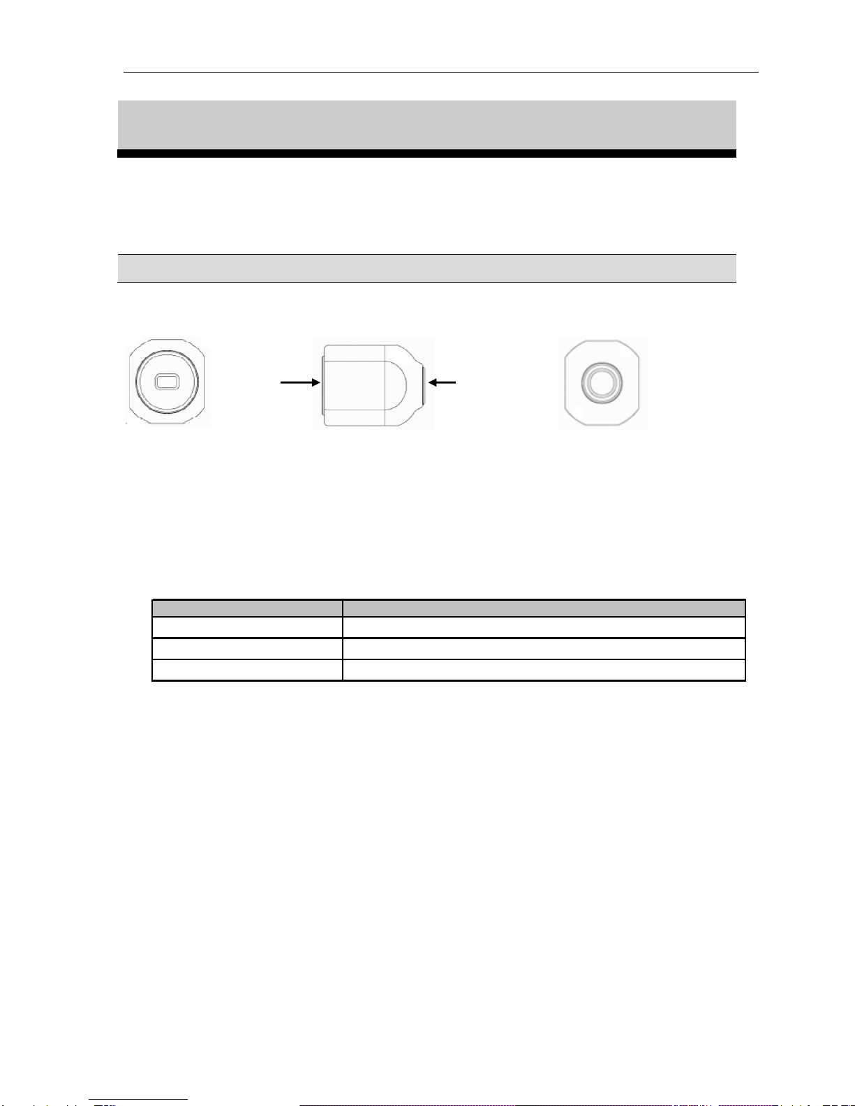
Product Description...................................................................................................................5
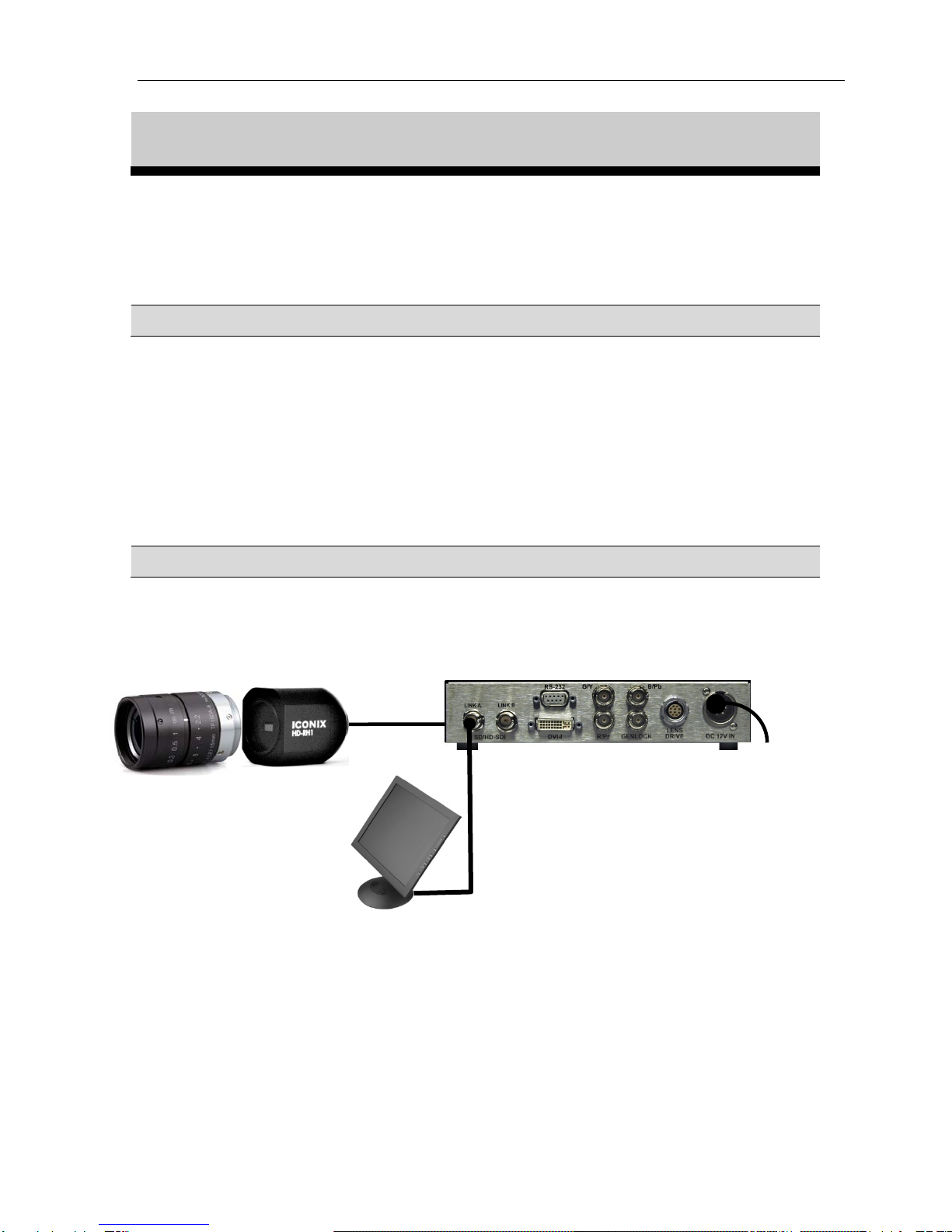
Quick Start: Hardware Setup...................................................................................................9
System Requirements............................................................................................. 9
Standard Hardware Connection........................................................................... 9
Standard Hardware Connection Tips................................................................ 10
Remote Connection.............................................................................................. 10
Safety Precautions................................................................................................ 10
Operation..................................................................................................................................11
Video Outputs....................................................................................................... 11
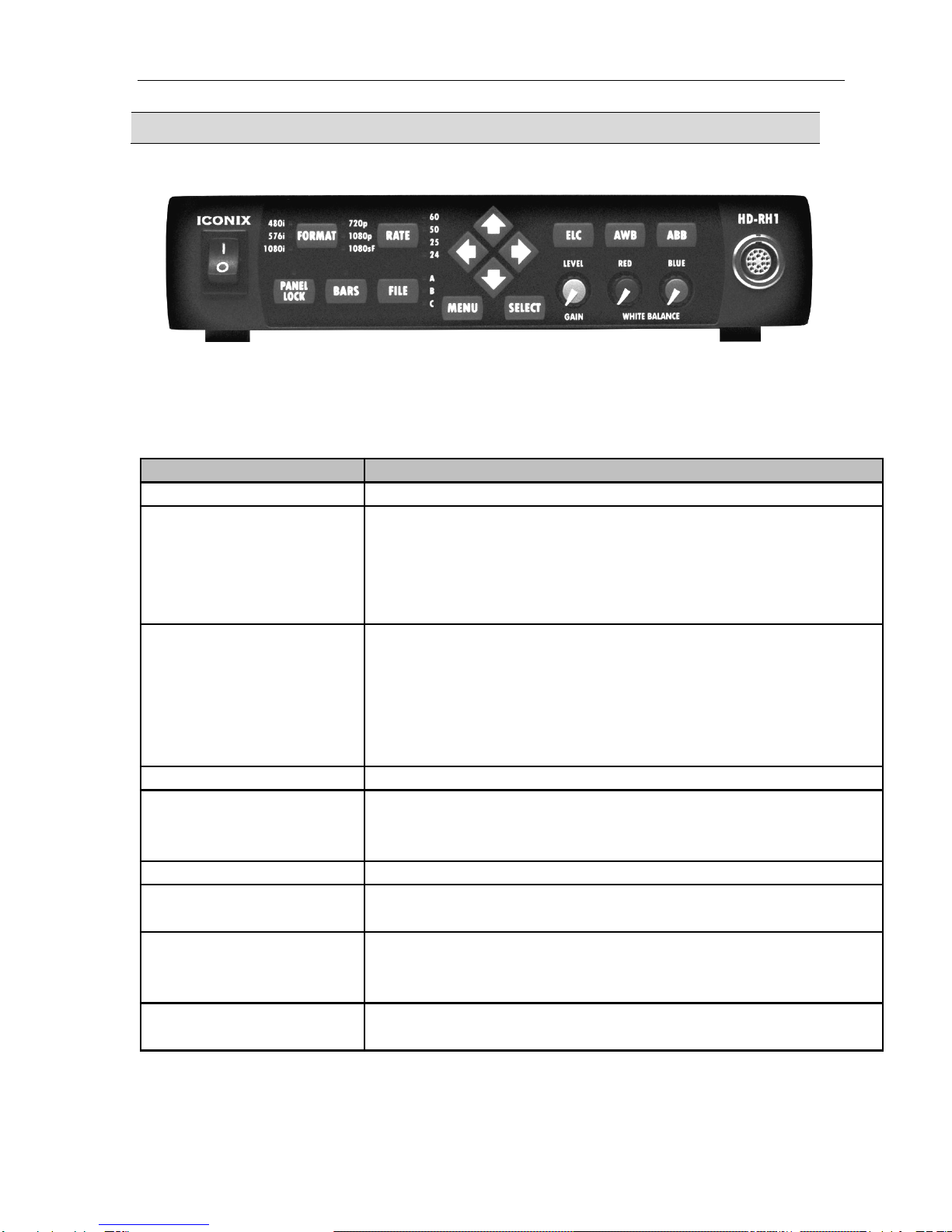
Selecting a Format and Rate: Front Panel ........................................................ 13
Selecting a Format and Rate: Menus................................................................. 14
Select a Scene File................................................................................................. 15
Electronic Level Control (ELC).......................................................................... 15
White Balance....................................................................................................... 16
How to White Balance: Automatic (AWB)........................................................ 16
How to White Balance: Manual.......................................................................... 17
Automatic Black Balance .................................................................................... 18
Panel Lock............................................................................................................. 19
Genlock.................................................................................................................. 20
Using the Menus.......................................................................................................................21
Navigating the Menus.......................................................................................... 21
Selecting a Menu Option and Parameter........................................................... 22
User Area On-Screen Entry................................................................................ 23
Video Output Menu .................................................................................................................24
Gain Menu ................................................................................................................................27
Shutter Menu............................................................................................................................28
White Balance Menu................................................................................................................31
Detail Menu...............................................................................................................................33
Level/Knee Menu .....................................................................................................................34
Gamma Menu...........................................................................................................................35
Matrix Menu.............................................................................................................................37
Feature Menu ...........................................................................................................................39
Lens Menu.................................................................................................................................40
Sync Menu.................................................................................................................................41

HD-RH1 User Manual Table of Contents
Table of Contents
2
Quick Reference.......................................................................................................................43
Menu Screen (showing factory defaults)............................................................ 43
Specifications........................................................................................................ 45
List of Figures
Figure 1. HD-RH1 Camera head components ...........................................................................5
Figure 2. CCU – front panel.......................................................................................................6
Figure 3. CCU connectors – rear panel......................................................................................8
Figure 4. Standard Hardware Connection..................................................................................9
List of Tables
Figure 1. HD-RH1 Camera head components ............................................................................................... 5
Table 1. Camera Head parts and functions ................................................................................................... 5
Figure 2. CCU – front panel........................................................................................................................... 6
Table 2. CCU buttons and functions – front panel........................................................................................ 6
Figure 3. CCU connectors – rear panel.......................................................................................................... 8
Table 3. CCU connectors and functions – rear panel.................................................................................... 8
Figure 4. Standard Hardware Connection...................................................................................................... 9
Table 4. Genlock Format compatibility...................................................................................................... 20
Table 5. Video Output Menu fields............................................................................................................. 24
Table 6. Gain Menu fields........................................................................................................................... 27
Table 7. Shutter Menu fields....................................................................................................................... 28
Table 8. Fixed Shutter Exposures available by frame rate.......................................................................... 29
Table 9. White Balance Menu fields........................................................................................................... 31
Table 10. Detail Menu fields....................................................................................................................... 33
Table 11. Level / Knee Menu fields............................................................................................................ 34
Table 12. Gamma Menu fields.................................................................................................................... 35
Table 13. Matrix Menu fields...................................................................................................................... 37
Table 14. Option Menu fields ..................................................................................................................... 39
Table 15. Lens Menu fields.......................................................................................................................... 40
Table 16. Sync Menu fields ......................................................................................................................... 41

HD-RH1 User Manual Warnings
3
Warnings
OPERATION PRECAUTION
Operation near any appliance which generates strong magnetic fields may give rise to
noise in the video signals.
CAUTION
Do not place unit into a confined space. Make sure adequate ventilation is available at all
times during use. Failure to do so may cause your unit to overheat and cause a fire hazard
or electric shock.
DO NOT REMOVE TOP COVER
Electric shock warning: there are no user serviceable parts inside.
CAUTION
Use with recommended accessories only.
WARNING
To reduce the risks of fire, shock and damage, do not expose this unit to rain, snow,
inclement weather, moisture, or high humidity. Keep this unit away from all liquids. Do
not place liquid containers on the top of the unit.

HD-RH1 User Manual Warnings
4
Warnings
USA:
WARNING: This equipment has been tested and found to comply with the limits for
Class A digital device pursuant to Part 15 of the FCC Rules. These limits are designed to
provide reasonable protection against harmful interference when the equipment is
operated in a commercial environment. This equipment generates, uses, and can radiate
radio frequency energy and, if not installed and used in accordance with the instruction's
manual, may cause interference to radio communications. Operation of this equipment in
a residential area is likely to cause interference in which case the user will be required to
correct the interference at his own expense.
The user is cautioned that changes and modifications made to the equipment without
approval of the manufacturer could void the user's authority to operate this equipment.
CANADA:
This Class A digital apparatus meets all requirements of the Canadian Interference-
Causing Equipment Regulations.
Cet appareil numerique de la classe A respecte toutes les exigences du Reglement sur le
materiel brouilleur du Canada.
DISPOSAL:
This product contains some components with regulated disposal due to environmental
considerations.
This symbol means that used electrical and electronic products should
not be mixed with general household waste.
For disposal or recycling information please contact your local
authorities, or the Electronics Industries Alliance.
If you wish to discard this product, please contact your local authorities or dealer and ask
for the correct method of disposal.

HD-RH1 User Manual Product Description
Iconix Video
5
Product Description
The HD-RH1 is a professional 3CCD remote head camera system that offers the versatility
of 720p, 1080i, 1080p, 480i (NTSC), and 576i (PAL) at all standard frame rates.
HD-RH1 Camera Head
Figure 1. HD-RH1 Camera head components
Table 1. Camera Head parts and functions
Part Description
Lens mount. Accepts C-mount style lens.
Cable terminal Cable connection to CCU.
Tripod mount (optional) 1/4-20 and 3/8-16 screw mounts.
Front Side Rear
Lens
mount Cable
terminal

HD-RH1 User Manual Product Description
6
HD-RH1 Camera Controller Unit (CCU)- Front
Figure 2. CCU – front panel
Table 2. CCU buttons and functions – front panel
Button Function
On/Off switch Powers camera on and off.
Format Press and hold to cycle through format options:
· The format does not change until you release the button.
· If you release on the current format setting, nothing changes.
· See Operations and/or Video Output Menu for more detail
on Format options.
Press and hold to cycle through rate options:
· Only rates for selected format are available.
· The rate does not change until you release the button.
· If you release on the current rate setting, nothing changes
· See Operations and/or Video Output Menu for more detail
on Rate options.
File Press and hold to cycle through scene files and select one.
Press to disable the front panel buttons and knobs. Panel is locked if
LED indicator is illuminated.
Press and hold to un-lock the front panel.
Bars Toggles the display of the color bar test pattern.
Menu Press to access the on-screen Menu, or to exit out of a menu without
making a selection. (See Using Menus )
Press to navigate to a menu, menu option, or parameter.
· Up and down scrolls through vertical list of menu options.
· Right / left displays parameters for a selected menu option.
Press to select/enable a menu option.
Note: A menu selection replaces a front panel setting and vice-versa.
Select
Rate
Panel Lock
Arrow Keys

HD-RH1 User Manual Product Description
7
HD-RH1 CCU (Cont’d)
Button Function
ELC
(+Level LED) Used to active ELC mode, or variable adjustment of the electronic
shutter.
Press and hold to perform an Automatic White Balance.
· Mode must be set to AWB in the White Balance Menu.
· See Operations – Video Output Setup for more detail.
ABB Press and hold to perform an Automatic Black Balance.
Gain/Level Knob When Manual Gain is enabled (via menu), use this knob to adjust
gain. When ELC is active, this knob is used to adjust the electronic
shutter
Press pop-out buttons to manually adjust red and blue gain levels
for Manual White Balance.
· Mode must be set to MANUAL in the White Balance Menu.
· See Operations – Video Output Setup for more detail.
AWB
Red knob/Blue knob

HD-RH1 User Manual Product Description
8
HD-RH1 CCU – Back Panel
Figure 3. CCU connectors – rear panel
Table 3. CCU connectors and functions – rear panel
Part Function
SD/HD-SDI
LINK A
LINK B
RS-232 Remote control interface.
DVI-I port Digital Video Interface – digital and analog outputs.
Y/G
Pb/B
Pr/R
GENLOCK BNC connector for reference sync source. Accepts analog input
signal, with either Tri-level (HD) or Bi-level (SD) sync.
LENS Interface for motorized lens control.
DC 12V IN DC power input (12V)
Single-link or Dual-Link HD-SDI (SMPTE-292)
Single-Link SD-SDI (SMPTE-259)
Three BNC connectors for analog video output.

HD-RH1 User Manual Quick Start: Hardware Setup
9
Quick Start: Hardware Setup
Once the hardware is connected, the camera is ready to use. The default format and rate is
720p59.94. To change the format and rate, see the Operations – Video Output Setup section.
System Requirements
Minimum System Requirements:
•C-mount lens suitable for 1/3 inch 3-CCD camera.
•Camera head cable.
•Video output cable for SDI, DVI, or RGB/YPbPr video.
•Monitor capable of displaying desired format and rate.
Standard Hardware Connection
Figure 4 illustrates the standard hardware connection for video output.
Figure 4. Standard Hardware Connection
.
CCU Rear Panel
Camera cable
connects to front o
f
controller
Lens Camera
head
DC power
supply
HD video monitor

HD-RH1 User Manual Quick Start: Hardware Setup
10
Standard Hardware Connection Tips
1. Verify that the CCU power switch is in the OFF position.
2. Attach the lens to the camera head.
3. Connect the camera head to the head cable. Line up the red dots on the connector
with the red dots on the camera and press in.
4. Connect the head cable into the CCU connector on the front panel.
5. Connect the video output monitor to the CCU via the appropriate cable.
6. Connect the DC power supply cord into the DC 12V connector on the controller back
panel.
7. Turn on the video monitor.
8. Flip the controller power switch to the ON position.
9. Press the BARS button and verify that color bars are displayed.
Remote Control / RCP
The HD-RH1 may be remotely controlled through the RS-232 remote control interface.
For more information, please contact an Iconix representative.
Safety Precautions
Please read and follow the safety guidelines before using the HD-RH1.
•12V power supply:
Nominal Voltage = 12V DC
Absolute Minimum = 9V DC
Absolute Maximum = 22V DC (peak)
3A maximum current requirement
•Do not use the camera in a place where it could come in contact with water, moisture,
steam, dust, or smoke. This could cause fire, electric shock, or camera failure.
•Use only the specified power source voltage and connection cord. The wrong source
could result in fire or electric shock.
•Do not use the camera in situations that exceed the temperature specifications
( 0° to 40° C ). This may cause malfunction and/or damage the camera.
•Do not touch the power cord or cables during a thunderstorm.

HD-RH1 User Manual Operation
11
Operation
Video Formats & Rates
The HD-RH1 is capable of generating images any of 31 format/frame rate combinations.
The following chart lists the available combinations:
720p Frame Rates
60 25
59.94 25n50
50 24
30 24n60
30n60 23.98
29.97 23.98n59.94
29.97n59.94
1080i Frame Rates
60
59.94
50
1080p Frame Rates
60 29.97
59.94 25
50 24
30 23.98
1080sF Frame Rates
30
29.97
25
24
23.98
480i Frame Rate
59.94
576i Frame Rate
50

HD-RH1 User Manual Operation
12
Video Formats & Rates (Cont’d)
Standard Definition Aspects
480i and 576i modes may also be set up for use in Anamorphic 16:9, Letterboxed 16:9, or
cropped 4:3 aspects.
1080sF/1080PsF
For purposes of brevity and clarity, the 1080sF nomenclature is used in this manual and in
the HD-RH1 operation to stand for what is also known as 1080PsF (Progressive
Segmented Frame).
Doubled 720p Frames
To accommodate certain recording decks available, the slower frame rates for 720p
(23.98-30Hz) have the option to be “pulled-up” to either a double (2:1 ratio) frame rate,
or a 3:2 style (actually a 2:5 frame-to-carrier ratio). The nomenclature used for this
device in the HD-RH1 is 720p24n60, which means 720p resolution with 24-frame native
content on a 60Hz carrier.
Menu Option Resulting Mode
24N60 720p23.98n59.94 (3:2)
24N60 720p24n60 (3:2)
25N50 720p25n50 (2:1)
30N60 720p29.97n59.94 (2:1)
30N60 720p30n60 (2:1)
720p Doubled-Frame Modes
Below is a chart diagramming the flow of frames for 720p24n60 or 23.98n59.94:
Content/Capture Frames
OP P OP P
720p24n60 output
111 22333 44
Ë
Ë
Ë
Ë
1234
Recording or Post-Production
Pull-Down
Final 24p result
1234
Ë
:effective frame
1234
OPERATIONAL NOTES:
•The Dual-Link signal for 1080p50, 1080p59.94, & 1080p60 is implemented per
SMPTE-372. Either link used independent of the other will appear as a single 1080i
4:2:2 signal. The Video Payload ID embedded in the digital stream can be used to
differentiate between 1080p and 1080i when in this mode.
•The HD-RH1 automatically switches to SD-SDI (SMPTE-259) when in 480i and
576i. The only mode available for SD-SDI is SL 422.

HD-RH1 User Manual Operation
13
Selecting a Format and Rate: Front Panel
Press and Hold buttons to cycle
through options
1. Press and hold the FORMAT key on the front panel to cycle through the format
options.
2. When the desired Format LED is lit, release the button. The Format is not selected
until the button is released. If the button is released on the format or rate that was
already active, nothing changes.
3. Press and hold the RATE key on the front panel to cycle through the available rates.
4. When the desired Rate LED is lit, release the button. The Rate is not selected until the
button is released.
OPERATIONAL NOTES:
•See the Video Output Menu section for a list of the rates available for each format.
•Only those rates valid for a format are available for selection.
•The 30 rate is only available from the Video Output menu. There is no LED indicator
on the front panel. If no LED is illuminated for RATE, then 30/29.97 is assumed.
•If F/P RATE mode is 1.001 in the Video Output menu, the whole number on the front
panel represents the fractional rate. For example, when 1.001 is active, and 60 is
selected on the front panel, 59.94Hz is the actual result. The factory default setting
for F/P RATE is 1.001. To use the front panel to select a non-fractional rate, first set
the F/P RATE to 1. (See Video Output Menu section.)
•The 720p format in rates 23.98 through 30 has the option of being frame-doubled to a
faster output rate. For example, 25-frame content can be output on a 50-frame signal.
For quick operation from the front panel this mode is enabled or disabled by the F/P
720P CARR option in the Video Output menu.
•A format/rate setting in the menu replaces the front panel setting and vice-versa.

HD-RH1 User Manual Operation
14
Selecting a Format and Rate: Menus
1. Access the Video Output Menu. (See Using Menus.)
2. Select the Format as follows:
Use up and down arrows to
select FRAME RATE
Press SELECT button
Use left & right arrow keys to
display desired option.
Press SELECT button.
3. Select the Rate as follows:
Use up and down arrows to
select RATE.
Press SELECT button.
Use left and right arrow keys to
display desired option.
Press SELECT button.
Press MENU button to exit
menu.
NOTES:
•See the Video Output Menu section for a list of the rates available for each format.
•Only those rates valid for a format are available for selection.
•A format/rate selection in the menu replaces the front panel selection and vice-versa.
V
I D E O O
U
T
>VIDEO FORMAT: 720P
RATE: 59.94
F/P RATE MODE: 1.001
F/P 720P CARR: NORMAL
SDI OUTPUT: SL 422
ANALOG MODE: YPBPR
VIDEO OUT
VIDEO FORMAT: 720P
>RATE: 59.94
F/P RATE MODE: 1.001
F/P 720P CARR: NORMAL
SDI OUTPUT: SL 422
ANALOG MODE: YPBPR

HD-RH1 User Manual Operation
15
Select a Scene File
There are three scene file locations – A, B, & C – for storing settings. Parameters are stored
in the currently selected/active scene file.
NOTES:
•If a feature setting is changed, the new setting replaces the setting stored in the
scene file.
•When the scene file is switched, the settings are immediately loaded from the values
stored in the newly active scene file.
To select a scene file using the front panel
1. Press and hold the FILE button on the front panel to cycle through the options.
2. When the LED next to the desired letter is lit, release the button.
NOTE: The scene file is not selected until the button is released.
Electronic Level Control (ELC)
The ELC button on the front panel can be used to manually adjust the Gain or Shutter. When
the Level LED is illuminated the ELC exposure can be manually adjusted using the
Level/Gain knob. When the LED is not illuminated the knob is only active if the Gain
MODE is set to MANUAL in the Gain Menu.
Electronic shutter and gain can be adjusted by either the menu or by the use of the ELC
button and Level/Gain knob on the front panel. See Gain Menu and Shutter Menu sections for
more information on menu parameter adjustments.
IMPORTANT
ELC and Manual gain cannot be used at the same time. If the user turns one of the two on,
the other will automatically be deactivated.
Electronic Level
Control Button
Level/Gain
Knob
The front panel FILE button can
switch among the scene files as
needed.

HD-RH1 User Manual Operation
16
White Balance
White Balance adjusts the camera for accurate white and color. There are two modes, selected
from the “White Balance” menu (see Using Menus and White Balance Menu.):
•AWB (Automatic White Balance)
•MANUAL
How to White Balance: Automatic (AWB)
1. Focus the camera on any white object.
2. Press and hold the AWB button on the front panel until the AWB IN PROGRESS
message appears. The camera automatically performs the white balance adjustment
and stores the data in the active scene file.
3. During the process, the following messages display:
Message Meaning
AWB IN PROGRESS AWB is in progress
AWB OK AWB has completed successfully
AWB FAIL AWB failed to complete
OPERATIONAL NOTES:
•The default preset area for AWB is A. The area preset may be changed via the White
Balance menu. (See Using Menus and White Balance Menu.)
•When the menu MODE is set to AWB, the Red and Blue knobs on the front panel are
disabled
Automatic White
Balance button
Red and Blue control knobs for
Manual White Balance.

HD-RH1 User Manual Operation
17
How to White Balance: Manual
1. Access the White Balance Menu and select MANUAL mode.
Use up and down arrows to
select MODE
Press SELECT BUTTON.
Use right arrow to display
MANUAL option.
Press SELECT button.
Press MENU button to exit
menu.
2. Focus the camera on the white object.
3. Press the red and blue pop-out knobs on the front panel. Turn to adjust while viewing
on monitor.
4. When adjustment is complete, press the red and/or blue knob in.
WHITE BALANCE
MODE: AWB
AWB R PAINT: 0
AWB B PAINT: 0
AWB AREA: A
USER AREA EDIT
SHD MODE: OFF
SHD AUTO: EXEC
SHD MANUAL R: 0
SHD MANUAL G: 0
SHD MANUAL B: 0

HD-RH1 User Manual Operation
18
Automatic Black Balance
Black balance adjustment is provided for accurate black coloration. Black balance is available
only on the front panel.
1. Close the iris or cap the lens to eliminate all light into the camera.
2. Press and hold the ABB button on the front panel to execute black balance.
3. During the process, the following messages display:
Message Meaning
ABB IN PROGRESS Calibration is in progress
ABB OK Calibration has completed successfully
ABB FAIL Camera cannot achieve black balance
4. The process may take several seconds to execute.
Automatic Shading Correction
Shading Correction is provided as a manual operation (see White Balance Menu), or as an
automatic correction function.
To automatically correct lens shading:
1. Point camera at a completely white target (no color, black, text, or graphics) such that
the screen is completely filled with white.
2. Set SHD MODE to AUTO in the White Balance menu.
3. Select “SHD AUTO: EXEC” in the White Balance menu to activate.
Automatic Black Balance button

HD-RH1 User Manual Operation
19
4. During the process, the following messages display:
Message Meaning
SHD IN PROGRESS Shading Correction is in progress
SHD OK Shading Correction has completed successfully
SHD FAIL Cannot achieve correction
SHD FAIL INVALID TARGET Target unsuitable for automatic correction
5. The process may take several seconds to execute.
NOTE: Auto Shading Correction may only be accurate for the zoom or iris setting at
which it was applied. For variable zoom and iris conditions, SHD MODE may be best
set to OFF, or MAN for manual adjustment.
Panel Lock
To reduce the risk of accidental changes to the camera while in use, the Panel Lock feature
may be used. To lock front panel menus and knobs, push the PANEL LOCK button, and the
LED will be illuminated.
While locked, the camera can be accessed and controlled via a remote connection.
To unlock the camera, press and hold the PANEL LOCK button until the LED turns off
(approx. one second).
Other manuals for HD-RH1
1
Table of contents
Other Iconix Security Camera manuals
Popular Security Camera manuals by other brands

bettini
bettini SD952B120-A/L User instructions

D-Link
D-Link DCS-7513 Technical specifications

Vicon
Vicon Surveyor 2000 Installation & operation manual

Qvis
Qvis IPTZ-IR20A user manual

American Dynamics
American Dynamics SpeedDome RHODULP-01 Installation and service guide

Allied Vision
Allied Vision PIKE Series Getting started