ICP DAS USA ACS-11-MF User manual

ACS-11-MF
User’s Manual (Ver.1.0, Apr./2016) ------------- 1
User’s Manual
www.icpdas.com
ACS-11(P)-MF
Access Control Reader

ACS-11-MF
User’s Manual (Ver.1.0, Apr./2016) ------------- 2
Warranty
All products manufactured by ICP DAS are under warranty regarding
defective materials for a period of one year from the date of delivery to the
original purchaser.
Warning
ICP DAS assumes no liability for damages resulting from the use of
this product. ICP DAS reserves the right to change this manual at any time
without notice. The information furnished by ICP DAS is believed to be
accurate and reliable. However, no responsibility is assumed by ICP DAS
for its use, or for any infringements of patents or other rights of third
parties resulting from its use.
Copyright
Copyright 2016 by ICP DAS. All rights are reserved.
Trademark
The names used for identification only may be registered trademarks
of their respective companies.
Document Revision
Version Date Description of changes
1.0 2016/04/18 First Release Revision

ACS-11-MF
User’s Manual (Ver.1.0, Apr./2016) ------------- 3
Table of Contents
1.
Introduction.......................................................................................5
1.1 Features............................................................................................. 6
1.2 Applications........................................................................................ 6
1.3 Specifications ..................................................................................... 6
2.
Hardware ...........................................................................................8
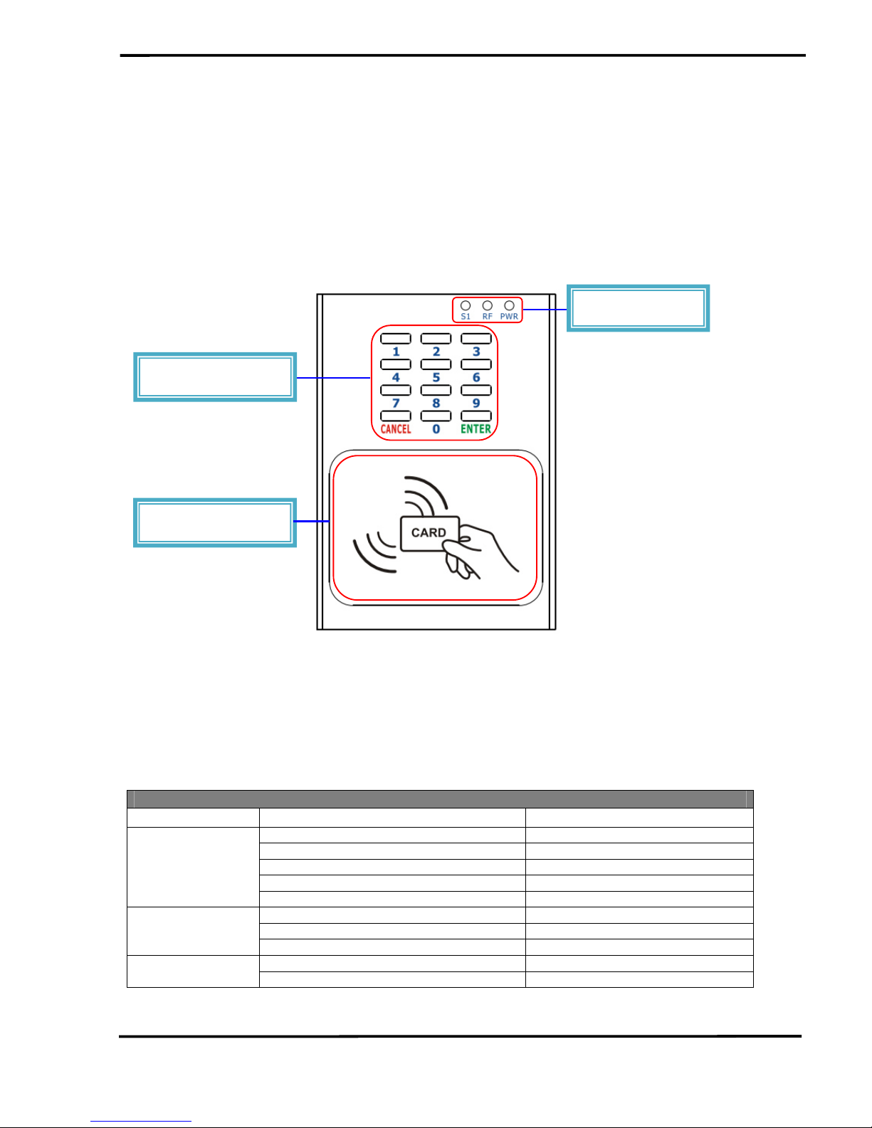
2.1 Front Panel ........................................................................................ 8
2.1.1 LED Indicator ................................................................................... 8
2.2 Back Panel......................................................................................... 9
2.3 Dimensions .......................................................................................11
2.4 Hardware Connections......................................................................11
2.4.1 Power and I/O wiring architecture ...................................................11
2.4.2 I/O connection ................................................................................ 13
2.5 Jumper Settings ............................................................................... 13
2.5.1 Terminator Resistor Settings .......................................................... 13
2.5.2 Operation Mode Settings................................................................ 14
2.6 Firmware update method ................................................................. 14
3.
Software...........................................................................................17
3.1 Installing the eSearch Utility............................................................. 17
3.2 Using the eSearch Utility to Assign an IP Address ........................... 17
3.3 Web Configuration ........................................................................... 20
3.3.1 IP Address Configuration................................................................ 21
3.3.2 Reader Configuration ..................................................................... 23
3.3.3 RTC Configuration.......................................................................... 25
3.3.4 Change Password Configuration.................................................... 25
3.4 Installation........................................................................................ 26
4.
Communication command Example..............................................31
4.1 Communication settings................................................................... 31
4.2 Command List.................................................................................. 31
4.2.1 Add Card Number .......................................................................... 31
4.2.2 Delete Card Number ...................................................................... 32
4.2.3 Delete All Cards’ Number ............................................................... 32
4.2.4 Card Number Inquiry...................................................................... 33
4.2.5 Add Password Number .................................................................. 34
4.2.6 Delete Password Number .............................................................. 34
4.2.7 Delete All Passwords’ Number ....................................................... 35
4.2.8 Inquire Access Record ................................................................... 35
4.2.9 Delete Access Record.................................................................... 36

ACS-11-MF
User’s Manual (Ver.1.0, Apr./2016) ------------- 4
4.2.10 Configure System Time.................................................................. 36
4.2.11 Check Door Position....................................................................... 37
4.3 CRC Calculation (CCITT-16)............................................................ 37

ACS-11-MF
User’s Manual (Ver.1.0, Apr./2016) ------------- 5
1. Introduction
Access Control systems are one of the most important infrastructures
for a safe, secure society. ACS-11-MF/ACS-11P-MF is an access control
reader that supports keypad and RFID induction of access control. It
integrates three functions of door access control, voice guidance and floor
control all in one, suitable for use in community door access and elevator
control. ACS-11-MF/ACS-11P-MF supports Ethernet and RS-485
communication interface and provides anti-sabotage sensor and door
position detection function which can consolidate the security of access
control systems and effectively enhance the service quality of
management.
The ACS-11P-MF has integrated Power-over-Ethernet (PoE), it allows
power and data to be carried over a single Ethernet cable, so a device can
operate solely from the power it receives through the data cable. This
innovation allows greater flexibility in office design, higher efficiency in
systems design, and faster turnaround time in set-up and implementation.
The ACS-11P-MF feature true IEEE 802.3af-compliant (classification,
Class 1) Power over Ethernet (PoE) using both Ethernet pairs (Category 5
Ethernet cable).
When using ACS-11P-MF module, you can choose ICP DAS “PoE”
Switch – “NS-205PSE” as the power source, NS-205PSE automatically
detects the connected devices whether they are PoE devices or not. This
mechanism ensures NS-205PSE to work with both PoE and non-PoE
devices coordinately at the same time.

ACS-11-MF
User’s Manual (Ver.1.0, Apr./2016) ------------- 6
1.1 Features
•Supports card type: Mifare
•Built-in Voice message function
•Supports Ethernet / RS-485 interface
•Built-in RTC and WDT
•Supports electronic lock control and door position detection
•Provides access records
•Max card capacity:8000 cards
•Supports elevator floor control (max. 16F)
1.2 Applications
1.3 Specifications
Table 1-1:System Specifications
Models ACS-11-MF ACS-11P-MF
CAN Bus
Baud rate(bps) 1M -
Specification ISO-11898-2, CAN 2.0A/B -
UART
COM RS-485(D+, D-)
Baud rate(bps) 9600
Format N, 8, 1
Ethernet
Controller 10/100Base-TX Ethernet Controller (Auto-negotiating, Auto MDIX)
Connector RJ-45 with LED indicator

ACS-11-MF
User’s Manual (Ver.1.0, Apr./2016) ------------- 7
PoE - Yes
Digital Input
Channels 4 2
Input type Dry Contact (Source), Wet Contact (Sink, Source)
Relay Output
Channels 2
Output Type Form C
Contact Rating 0.5A 120VAC / 2A 30VDC
Micro Switch
Channels 1
Circuit arrangement SPDT
Contact Rating 6A 125/250VAC
RFID
Supported Card Mifare S50
Standard ISO 14443 A
Power
Reverse Polarity Protection Yes
Powered from CN1 Connector 10 ~ 30 VDC -
Powered from PoE - Yes, IEEE 802.3af, Class1
Consumption 2.0W 1.7W
Mechanical
Installation Wall Mounting (Suitable for the outlet box in United States)
Dimensions 83mm x 120mm x 28mm (W x L x H)
Environment
Operating Temperature -20℃~ +60℃
Storage Temperature -30℃~ +80℃
Humidity 10% ~ 90%, non-condensing

ACS-11-MF
User’s Manual (Ver.1.0, Apr./2016) ------------- 8
2. Hardware
2.1 Front Panel
The front panel of the ACS-11(P)-MF module contains the Keypads,
RFID induction area and status LEDs.
Figure 2-1:Front Panel of the ACS-11(P)-MF
2.1.1
LED Indicator
Table 2-1:System Status Indicator
System Status Indicator
LED Module Status LED Status
Default IP operation mode Blink per 100 ms
Camera control module connection failed Blink per 1000 ms
Elevator control module 1 connection failed Blink per 2000 ms
Elevator control module 2 connection failed Blink per 3000 ms
PWR
Power failure Off
RFID induction Blink
Firmware update mode Blink per 500 ms
RF
Idle Off
Data transmission Blink
S1
Idle Off
Status Indicator
Keypads
Induction area

ACS-11-MF
User’s Manual (Ver.1.0, Apr./2016) ------------- 9
2.2 Back Panel
The back panel of the ACS-11(P)-MF module contains the Ethernet
port and power, signal connectors.
Figure 2-2:ACS-11-MF Connector Assignment
Table 2-2: ACS-11-MF Pin Assignment
Connector Type Pin Assignment Description
CN1
GND VDC Power (+10V~+30 VDC)
CN2
DI0
G
DI1
G
DI2
G
DI3
G
DI0(Door position detection)
DI1(Electric lock trigger)
DI2/3(n/a)
(Digital Input, Dry Contact)
CN3
COM NO NC Anti-sabotage detection
(Relay Output)
NC
COM
CN4
NO
Electronic lock control
(Relay Output)
NC
COM
CN5
NO
Door position alarm output
(Relay Output)
CAN(CAN_H/CAN_L)
Baud Rate (bps) : 1M
CN6
CAN_L
CAN_H
D+ D-
RS-485(D+/D-)
Baud Rate (bps): 9600
Parity: NONE
Data Bits: 8
Stop Bits: 1

ACS-11-MF
User’s Manual (Ver.1.0, Apr./2016) ------------- 10
Figure 2-3:ACS-11P-MF Connector Assignment
Table 2-3: ACS-11(P)-MF Pin Assignment
Connector Type Pin Assignment Description
CN1
D+ D-
RS-485(D+/D-)
Baud Rate (bps): 9600
Parity: NONE
Data Bits: 8
Stop Bits: 1
CN2
DI0 G DI1 G
DI0(Door position detection)
DI1(Electric lock trigger)
(Digital Input, Dry Contact)
NC
COM
CN3
NO
Electronic lock control
(Relay Output)
NC
COM
CN4
NO
Door position alarm output
(Relay Output)
CN5
COM NO NC Anti-sabotage detection
(Relay Output)

ACS-11-MF
User’s Manual (Ver.1.0, Apr./2016) ------------- 11
2.3 Dimensions
The following
diagrams provide the dimensions of the ACS-11(P)-MF
module and can be used as a reference when defining the specifications
for any custom enclosures. All dimensions are in millimeters.
Figure 2-4:Dimension of the ACS-11(P)-MF Module
2.4 Hardware Connections
2.4.1 Power and I/O wiring architecture
ACS-11(P)-MF series modules provide a variety of communication
interfaces to suit a range of applications. Below is a description of the
configuration for simple applications using the ACS-11(P)-MF.

ACS-11-MF
User’s Manual (Ver.1.0, Apr./2016) ------------- 12
Figure 2-5:ACS-11-MF Power and I/O wiring architecture
Figure 2-6:ACS-11P-MF Power and I/O wiring architecture

ACS-11-MF
User’s Manual (Ver.1.0, Apr./2016) ------------- 13
2.4.2 I/O connection
Figure 2-7:Wire connection
2.5 Jumper Settings
2.5.1 Terminator Resistor Settings
According to the ISO 11898 specifications, the CAN Bus network must
be terminated by two terminal resistors (120
Ω
) for proper operation, as
shown in the below figure.
Figure 2-8:Terminal Resistor
Therefore, the ACS-11-MF module supplies a jumper for users to
active the terminal resistor or not. If users want to use this terminal resistor,
please open the ACS-11-MF cover and use the JP3 to activate the 120
Ω
terminal resistor built in the module, as the Table 2-4. Note that the default
setting is active.

ACS-11-MF
User’s Manual (Ver.1.0, Apr./2016) ------------- 14
Table 2-4: Terminal Resistor Jumper (ACS-11-MF)
Jumper Position
Enable (default) Disable
2.5.2 Operation Mode Settings
ACS-11(P)-MF module supplies a jumper for users to select the
firmware operation or firmware update mode of the module.
Table 2-5: Operation Mode Setting Jumper (ACS-11(P)-MF)
Jumper Position
Firmware operation mode
(default)
Firmware update mode
2.6 Firmware update method
There are three ways to make the product enters "Firmware update
mode", please refer to the following settings mode. When ACS-11(P)-MF
is in firmware update mode, the RF LED will blink per 500 ms. Users can
update the firmware of the ACS-11(P)-MF module by the Ethernet
interface.
Item
Setting Mode
1
Press and hold the No.0 key for 10 seconds
2 Press and hold the No.0 key, and reset the power of ACS-11(P)-
MF
3 Set the JP2 to the "Firmware update mode" position as Table 2-
5, and reset the power of ACS-11(P)-MF
Please follow the below steps to complete the firmware updating
process.
Step1. Make the product enters "Firmware update mode".
Step2. Network configuration of computer.

ACS-11-MF
User’s Manual (Ver.1.0, Apr./2016) ------------- 15
Entry the IP address as "192.168.0.x", where "x" is a number
that between 1 and 254 except 1, Subnet mask as
"255.255.0.0". Finally, press "OK" button.
Figure 2-9:Network configuration
Step3. Establish a network connection between PC and
ACS-11(P)-MF
Step4. Launch the firmware update tool "FW_Update_Tool_v2.00.exe"
1. Select the connection network interface of ACS-11(P)-MF
2. Set IP address as: IP 192.168.0.1
3. Click “Browser” button to choose firmware file (ACS-11-MF_vx.fw)
4. Click “Firmware Update” button to start firmware updating process
5. After firmware update is complete, please reset the power of ACS-
11(P)-MF

ACS-11-MF
User’s Manual (Ver.1.0, Apr./2016) ------------- 16
Figure 2-10:Firmware update process

ACS-11-MF
User’s Manual (Ver.1.0, Apr./2016) ------------- 17
3. Software
3.1 Installing the eSearch Utility
The eSearch
Utility is a useful tool that provides a quick and easy
way to configure the Ethernet settings to the ACS-11-MF from a PC.
Step 1:Install the eSearch
Utility tool
The eSearch Utility can be obtained either from the companion CD at:
CD:\Napdos\Software\eSearch\
Or from the ICP DAS FTP site at:
http://ftp.icpdas.com/pub/cd/tinymodules/napdos/software/esearch/
Step 2:Follow the instructions in the Setup Wizard to complete the
installation. After the installation has been completed, a new short cut for
the eSearch
Utility will be displayed on your desktop.
3.2 Using the eSearch Utility to Assign an IP Address
The factory default IP settings are as follows:
Item Default
IP Address 192.168.0.1
Subnet Mask 255.255.0.0
Gateway 192.168.0.254(Fixed)

ACS-11-MF
User’s Manual (Ver.1.0, Apr./2016) ------------- 18
Step 1:Run the eSearch
Utility
Double-click the "eSearch
Utility" shortcut on your desktop.
Step 2 :Press the "Search Servers" button to search for your
module
After pressing the "Search Servers" button, the utility will perform a
search of all ACS-11-MF modules on your network.
Step 3:Click the "ACS-11-MF" item for which you want to change
the IP setting and then click the "configuration(UDP)" button.
All ACS-11-MF series module are IP-based devices that may not be
suitable for your network using the default IP address. Therefore, you
must first assign a new IP address to the ACS-11-MF series module
depending on your network settings.

ACS-11-MF
User’s Manual (Ver.1.0, Apr./2016) ------------- 19
After the search has been completed, click the name of the module,
and then click the "configuration(UDP)" button to open the Configuration
Server dialog.
Step 4:Assign a new IP address and then click the "OK" button
Contact your Network Administrator to obtain the correct network
configuration information. Modify the network settings as necessary and
then click the “OK” button. The ACS-11-MF series module will use the
new settings immediately. (ACS-11-MF doesn’t support DHCP function)
Step 5:After save the settings, ACS-11-MF will automatically reboot
and then press the "Search Servers" button to check the IP settings
After completing and saving the settings, ACS-11-MF will
automatically reboot and then use the eSearch
Utility to perform another
search for the module to make sure that the IP settings are correct. See
Step 2 for details.

ACS-11-MF
User’s Manual (Ver.1.0, Apr./2016) ------------- 20
3.3 Web Configuration
The ACS-11-MF series contains an advanced web configuration
system that provides users with access to ACS-11-MF series
applications through a standard web browser.
Step 1:Open a browser
Use a standard internet browser to view the ACS-11-MF web pages,
such as Google Chrome, Mozilla Firefox and Internet Explorer are
reliable and popular internet browsers that can be used to configure
ACS-11-MF series module.
Step 2:Enter the URL address for the ACS-11-MF
If you haven’t changed the default IP address of the ACS-11-MF
module, please refer to section 3.2. Using the "eSearch
Utility" to assign
an IP address to configure it.
Step 3:Enter the Login Password
After entering the IP address, the main login dialog page will be
displayed prompting you to enter a password. The factory default
password is as follows; Click the "Submit" button to continue.
Item Default
Password Admin
This manual suits for next models
1
Table of contents