ICP DFS2A309J1A Dimensions and installation guide

Manufacturer reserves the right to discontinue, or change at any time, specifications or designs without notice and without inc
Printed in Israel Pg 1
Installation Start-Up and Service Instructions
CONTENTS
Page
SAFETY CONSDERATONS . . . . . . . . . . . . . . . . . . . . . . . . .1
GENERAL . . . . . . . . . . . . . . . . . . . . . . . . . . . . . . . . . . . . . . . . . 1-4
NSTALLAT ON . . . . . . . . . . . . . . . . . . . . . . . . . . . . . . . . . . . 4-11
ndoor Unit nstallation . . . . . . . . . . . . . . . . . . . . . . . . . . . . . 4
. . . . . . . . . . . . . . . . . . . . . . . . .6
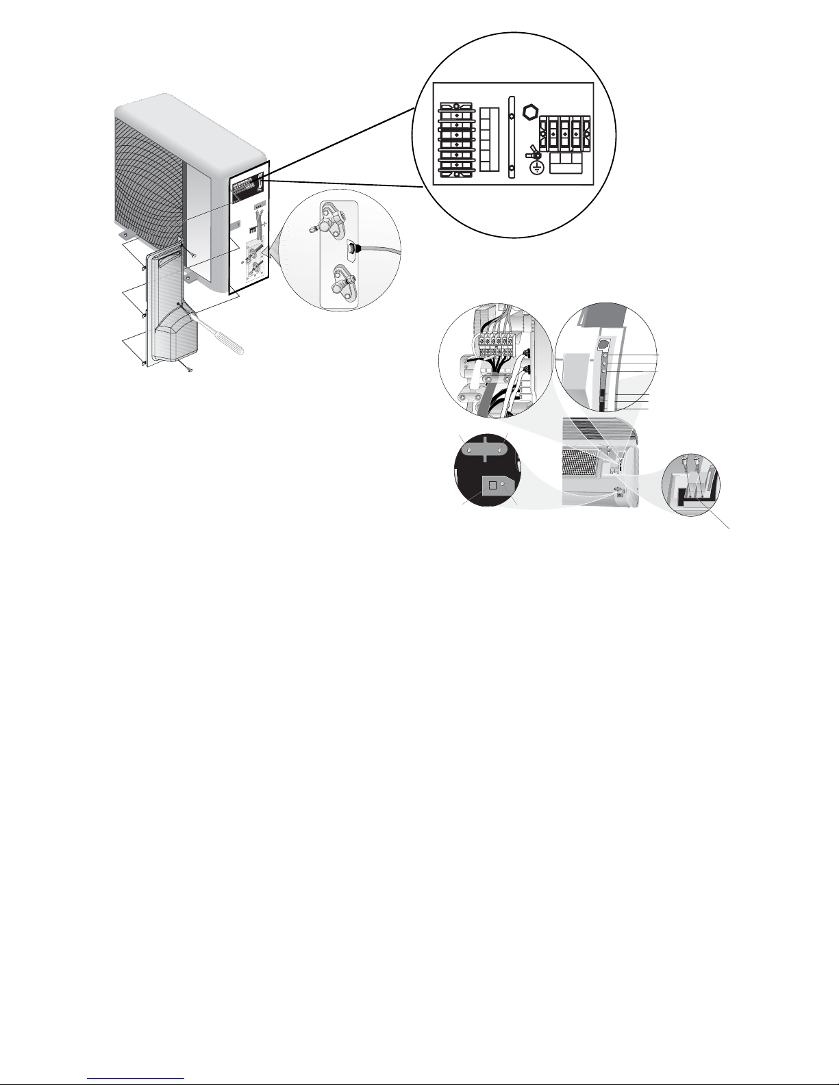
Power Supply. . . . . . . . . . . . . . . . . . . . . . . . . . . . . . . . . . . . . . . .7
Leak Test . . . . . . . . . . . . . . . . . . . . . . . . . . . . . . . . . . . . . . . . . . . .7
START-UP . . . . . . . . . . . . . . . . . . . . . . . . . . . . . . . . . . . . . . . . . .11
System Checks. . . . . . . . . . . . . . . . . . . . . . . . . . . . . . . . . . . . .11
CARE AND MA NTENANCE. . . . . . . . . . . . . . . . . . . . . . . . .11
. . . . . . . . . . . . . . . . . . . . . . . . . . . . . . . . . .11
Indoor Units. . . . . . . . . . . . . . . . . . . . . . . . . . . . . . . . . . . . . . . .11
To Clean the ndoor Unit Front Panel . . . . . . . . . . . . . . .11
To Clean ndoor Coil. . . . . . . . . . . . . . . . . . . . . . . . . . . . . . . .11
. . . . . . . . . . . . . . . . . . . . . . . . . .11
SERVCE . . . . . . . . . . . . . . . . . . . . . . . . . . . . . . . . . . . . . . . . . . .11
TROUBLESHOOTNG. . . . . . . . . . . . . . . . . . . . . . . . . . . .12-15
SAFETY CONS DERAT ONS
Installing, starting up, and servicing air-conditioning equip-
ment can be ha ardous due to system pressures, electrical
components, and equipment location (roofs, elevated struc-
tures, etc.).
Only trained, qualified installers and service mechanics
should install, start-up, and service this equipment.
Untrained personnel can perform basic maintenance func-
tions such as cleaning coils. All other operations should be
performed by trained service personnel.
When working on the equipment, observe precautions in
the literature and on tags, stickers, and labels attached to the
equipment.
Follow all safety codes. Wear safety glasses and work
gloves. Keep quenching cloth and fire extinguisher nearby
when bra ing. Use care in handling, rigging, and setting bulky
equipment.
GENERAL
System Requirements
Consult local building codes and National Electrical
Code (NEC, U.S.A.) for special installation requirements.
Use only type G or C fuses.
Use single length power cable without extension.
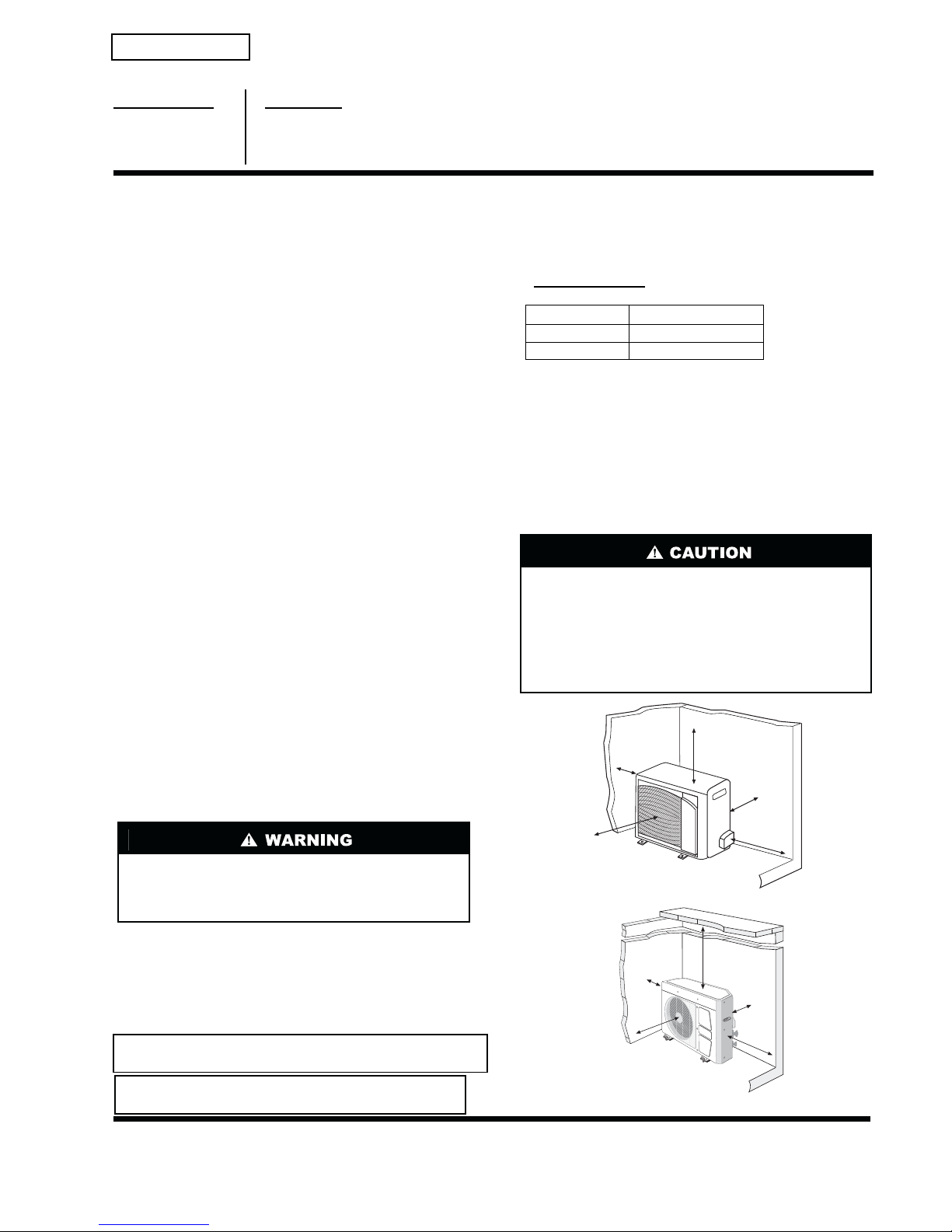
Allow sufficient space for airflow clearance on condens-
ing units for wiring, refrigerant piping, and servicing
unit. See Fig. 1 and 2 for minimum required distances
between unit and walls or ceilings.
Indoor and outdoor units should be installed at a
Maximum line length of 50 ft, and
vertical separation of 30 ft.
Do not install indoor units near a direct source of heat
such as direct sunlight, steam or flame.
Before installing or servicing system, always turn off main
power to system and install lockout tag on disconnect.
There may be more than one disconnect switch. Electrical
shock can cause personal injury.
IMPORTANT: The Indoor unit & the inter units cable voltage
is 30 VDC
IMPORTANT: Each refrigerant line must be insulated
separately. See line sizing requirements in table 2.
Do not bury more than 36 in. of refrigerant pipe in the
ground. If any section of pipe is buried, there must be a
6 in. vertical rise to the valve connections on the outdoor
units. If more than the recommended length is buried,
refrigerant may migrate to the cooler buried section during
extended periods of system shutdown. This causes refriger-
ant slugging and could possibly damage the compressor at
start-up.
DFS2A/H 09,12,18
Duct Free Systems
Fig. 1B Outdoor Unit Clearances
Fig. 1A Outdoor Unit Clearances
These instructions cover the installation, start-up and servicing
of DFC2A/DFC2H outdoor and DFF2A/DFF2H indoor units
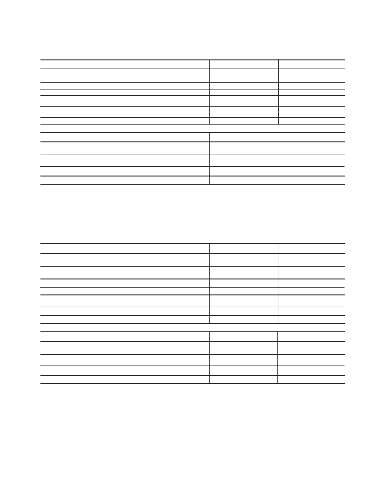
cooling only and heat pump duct free systems. See Table 1 for
parts included. See Tables 2 and 3 for Physical Data.
51302618915 0106
TOP (min.)
2 (0.6m)
LEFT (min.)
6 (0.15m)
RIGHT (min.)
2 (0.6m)
FRONT (min.)
2 (0.6m)
REAR (min.)
6 (0.15m)
Max. cable length. Total voltage drop should not exceed 1V.
Therefore max. length:
For #18 AWG 24.3 Feet (7.4 m)
For #16 AWG 37.7 Feet (11.5 m)
For #14 AWG 50.0 Feet (18 m)
Outdoor Units . . . .
Outdoor Unit Installation . . .
Air Filters for Indoor Units
LEFT(min.)
6 (0.15m)
TOP(min.)
2 (0.6m)
REAR(min.)
6 (0.15m)
RIGHT(min.)
2 (0.6m)
FRONT(min.)
2 (0.6m)
Cooling Model Heat Pump
DFS2A309J1ADFS2H309J1A
DFS2A312J1A DFS2H312J1A
DFS2A318K1ADFS2H318K1A
421 01 9217 00

2
Table 1 Parts List High Wall Units
TEM QTY D AGRAM
Mounting Bracket 1
DFF2A/DFF2H 09, 12 or DFF2A/DFF2H 18
Long Screws 8
Outdoor Sensor
Connecting Cable 1
Absorption Cushions 4
Electric Terminals 8
Remote Controller Rack 1 rack with 2 screws
Remote Controller
and Batteries 1
1
Owners Manual 1
1
(Available for HEAT PUMP ONLY)
(OPTIONAL)
(Not included)
Insulation for indoor Fittings
Wall mounted Receiver RTX
NADA001TW
TURBO-JET
ECONOMY

3
Table 2 Physical Data Cooling Only
LEGEND
*Units are shipped with a factory charge based on 25 ft of refrigerant lines.
Table 3 Physical Data Heat Pump
LEGEND
*Units are shipped with a factory charge based on 25 ft of refrigerant lines.
NO E: Standard Ambient Operating Limitations 55 ºF to 125 ºF (12.7 ºC to 51.6 ºC).
INDOOR UNIT DFF2AH09J1A DFF2AH12J1A DFF2AH18J1A
COOLIN CAPACITY (Btuh)
SEER
SYSTEM CHAR E (lb)* 2.7 3.1 4.1
MOISTURE REMOVAL (pt/hr)
AIRFLOW
High Cfm 350 400 670
DIMENSIONS L x H x W (in.) 32 3/32 x 10 15/64 x 7 9/32 32 3/32 x 10 15/64 x 7 9/32 42 1/2 x 11 5/8 x 7 9/32
NET WEI HT (lb) 19.0 19.0 27.5
OUTDOOR UNIT DFC2A309J1A DFC2A312J1A DFC2A318K1A
TUBE CONNECTIONS
Vert Lift/Vert Drop/Max Length (ft) 30/30/50 30/30/50 30/30/50
NOMINAL LINE SIZIN
Mixed Phase...Suction (in.)
DIMENSIONS L x H x W (in.) 28 3/4 X 21 1/4 X 10 7/16 35 7/16 X 25 3/16 X 12 9/32 43 5/16 X 25 3/16 X 15 3/4
NET WEI HT (lb) 73 114 136
SEER Seasonal Energy Efficiency Ratio
COOLIN CAPACITY (Btuh) 9,000 11,600 19,000
SEER 13.0 13.0 13.0
HEATIN CAPACITY (Btuh) 8,600 11,800 18,300
HSPF 7.7 7.7 7.7
SYSTEM CHAR E* (lb) 2.7 3.1 4.1
MOISTURE REMOVAL (pt/hr)
AIRFLOW
High Cfm 350 400 670
DIMENSIONS L x H x W (in.)
NET WEI HT (lb)
TUBE CONNECTIONS
Vert Lift/Vert Drop/Max Length (ft)
NOMINAL LINE SIZIN
Mixed Phase...Suction (in.)
DIMENSIONS L x H x W (in.)
SHIPPIN WEI HT (lb)
HSPF Heating Seasonal Performance Factor
SEER Seasonal Energy Efficiency Ratio
9,000 11,600 19,000
13 13 13
3/8...5/8
1/4...1/21/4...1/2
32 3/32 x 10 15/64 x 7 9/32 32 3/32 x 10 15/64 x 7 9/32 42 1/2 x 11 5/8 x 7 9/32
19.0 19.0 27.5
30/30/50 30/30/50 30/30/50
28 3/4 X 21 1/4 X 10 7/16 35 7/16 X 25 3/16 X 12 9/32 43 5/16 X 25 3/16 X 15 3/4
73 114 136
3/8...5/8
1/4...1/21/4...1/2
2.6 4.5 5.3
2.6 4.5 5.3
INDOOR UNIT DFF2HH09J1A DFF2HH12J1A DFF2HH18J1A
OUTDOOR UNIT DFC2H309J1A DFC2H312J1A DFC2H318K1A

4
NSTALLAT ON
Plan the installation carefully to avoid component failures
and make installation easier.
ndoor Unit nstallation
REFRIGERANT LINE ROUTING The refrigerant lines
may be routed in any of the four directions shown in Fig. 3.
INSTALL THE MOUNTING BRACKET
1. Carefully remove the mounting bracket, which is
connected to the back of the indoor units base with screws.
2. Position the mounting bracket on the wall and level it
using a spirit level (see Fig. 2 for minimum required
clearance distances).
3. Mark the four drilling holes on the wall, as they appear in
Fig. 4.
4. Drill the holes, insert the wall plugs and use four long
screws to attach the mounting bracket to the wall.
5. Check that the bracket is leveled and securely fastened to
the wall.
DRILL A HOLE IN THE WALL FOR DRAINAGE AND
INTER-UNIT CONNECTIONS To make the connections
between the indoor and outdoor units, drill a 3-in. hole through
the wall for the refrigerant lines, drainage hose and control
cable passage as shown in Fig. 5.
1. Mark the center of the hole to be drilled according to the re-
frigerant line routing used and dimensions shown in Fig. 4.
2. Make sure to drill outwards and downwards, so that the
opening in the outside wall is at least 1/2-in. lower than
the opening on the inside.
3. Make sure the drainage hose is at the bottom side of the
hole.
4.If refrigerant line route no. 1, 2 or 4 are used, use a small
saw blade to carefully remove the corresponding plastic
covering on the side panel.
5. Run the outdoor sensor cable, electrical cable, refrigerant
lines, and drainage tube through the hole.
6. Fill the remaining wall hole gap with an appropriate
sealant material.
Fig. 2 ndoor Unit Clearances
Fig. 4 Mounting Bracket DFF2A/DFF2H 09, 12
Fig. 4 Mounting Bracket DFF2A/DFF2H 18
REFRIGERANT
LINES
DRAINAGE
TUBE
ELECTRICAL
CABLE
1/2.IN. MIN
3-IN.
INDOOR OUTDOOR
Fig. 5 Drill Holes
(Optional for HEAT PUMP SYSTEMS)
OUTDOOR SENSOR CABLE
6" (0.15m)
(1.8-2.5m)
min.
min.
min.
6'-8'3"
8"
(0.2m)
8"
(0.2m)
Fig. 3 Refrigerant Lines
4
23
1
3½
35
15
2
2
1
6
18
7¾
2¾
2¾
13¾ 2¾
10 5
10
3
25
2
2
09, 12
17
9
16
11
32
23 32
5
3½
1¾
32
11
4
1
32
19
1¾
8
5
8
1
2¾

2. Put the control box cover and grille frame back on using
the appropriate screws (Steps 3 and 4 of Wire the Indoor
Unit section). Put the grille insert back on.
REASSEMBLE
Fig. 8 ndoor Unit Mounting
5
Fig. 9 Outdoor Sensor Connection
123456
ON
HEAT PUMP
Model-12 DIP Switches location
(on the Control Bo side)
HEAT PUMP
Models-09,18 DIP Switches location
(on the Control Bo side)
Inter unit cable clamp
TH1
TH2
TH3
Display
connection
Inter unit
terminal block
30 VDC
123456
ON
123456
ON
123456
ON
COOLING ONLY
Model-12 DIP Switches location
(on the Control Bo side)
COOLING ONLY
Models-09,18 DIP Switches location
(on the Control Bo side)
Standard Dip Switches
status from the factory
(Heat pump only)
MAKE DRAINAGE CONNECTIONS
1. Connect the unattached end of the drainage tube to the
drainage hose outlet.
2. Seal the drainage connection to prevent leakage.
3. Make sure there are no kinks, U bends or flattened
sections in the tube.
4. Check that the drainage functions properly. Fill the pan
below the units coil with water and observe that it freely
drains out.
5. Make sure the drainage hose is at the bottom side of the
wall through-hole (see Fig. 5).
outdoor sensor cable towards the lower right hand corner
of the indoor unit.
WIRE THE INDOOR UNIT
2. Remove the unit's front panel by lifting the lower part
and pulling it gently outward and upward. See Fig. 6.
5. Pull downwards and outwardston the bottom of the grille
and gently raise the frame of the top of the unit.
3. Remove the two screws from the control box cover
and take off the cover. See Fig. 7. Save the screws to reassemble.
6. Once all covers are off, mount the unit onto the wall
mounting bracket. See Fig. 8.
NOTE: Leave covers off until after the Making Drainage
Connections section.
7. Route the interconnecting units electric cable and the
Make sure that all wires and screws are firmly fastened.
Loose wires or connections can cause damage and present
a fire ha ard.
1.Strip the cables back1/4 inch.
8.Make sure that the wires are connected in accordance
with the wiring diagram on the inside of the unit front
cover or within this instruction manual.
9. Secure the control cables to the strain relief.
10. For heat pump systems only, connect the outdoor sensor
TH3 to its mating black terminal. See Fig. 9.
NOTE: In general wiring the indoor unit does not require the
removal of the grille frame but in case of need do as follow:
4. Remove the two screws from the air discharge opening.
Save the screws to reassemble. See Fig. 7A.
1. Connect the display connector to the display panel
printed circuit board.
Fig. 6 Remove Grille Insert
Fig. 7 Remove Control Cover
Mount the indoor unit on the mounting bracket
Gently push with
the arrow direction
1
2
FILTER
IR
RECEIVER
POWER/AIRCOND TIMER
FILTER
IR
RECEIVER
POWER/AIRCOND TIMER
Fig. 7A---Remove the screws from the air discharge opening.

6
CONNECT REFRIGERANT LINES Connect the ends of
the refrigerant lines to their appropriate fittings, following these
guidelines:
To connect the refrigerant lines use only L type sealed,
dehydrated copper refrigerant tubing. No other type of tubing
may be used. Use of other types of tubing will void the manu-
facturers warranty.
Do not open service valves or remove protective caps from
tubing ends until all the connections are made.
Take care to avoid kinks or flattening of the tubing.
Bend tubing with special bending tools to avoid the forma-
tion of sharp bends.
Keep the tubing free of dirt, sand, moisture and other con-
taminants to avoid damaging the refrigerant system.
Avoid sags in the suction line to prevent the formation of oil
traps.
Insulate both refrigerant lines separately with 3/8-in. walled
thermal pipe insulation. Inserting the tubing into the insulation
before making the connections can save time and improve in-
sulation. The suction and mixed phase lines should never come
in direct contact.
ATTACH THE REMOTE CONTROLLER RACK
1. Use the two screws supplied with the controller to attach
the rack to the wall in the location selected by the custom-
er (see Fig. 10 ).
2. Install batteries in the remote control.
3. Place remote control into remote control rack.
4. For remote control operation, refer to the unit Owners
Manual.
Outdoor Unit nstallation
NOTE: The outdoor unit must be installed on a solid surface
(mounting base).
1. Place the rubber absorption cushions (supplied with the
outdoor unit) under the units feets to prevent vibrations.
2. Fasten the outdoor unit legs to the mounting base, as
shown in Fig. 12. The cushion goes between the legs and
the mounting base.
3.Be sure that the unit is leveled.
MAKE REFRIGERANT PIPING CONNECTIONS (OUT-
DOOR UNIT) To connect the refrigerant lines:
Use only L type sealed, dehydrated copper refrigerant
tubing. No other type of tubing may be used. Use of other types
of tubing will void the manufacturers warranty.
Do not open service valves or remove protective caps from
tubing ends until all the connections are made.
Bend tubing with special bending tools to avoid the forma-
tion of sharp bends. Take care to avoid kinks or flattening of
the tubing.
Keep the tubing free of dirt, sand, moisture, and other con-
taminants to avoid damaging the refrigerant system.
Avoid sags in the suction line to prevent the formation of oil
traps.
Insulate each tube with 3/8-in. walled thermal pipe insula-
tion. Inserting the tubing into the insulation before making the
connections will save time and improve installation
The suction and mixed-phase lines should never come in direct
contact.
Fig. 10 Attach Rack to the Wall
POWER SUPPLY
TERMINAL BLOCK
HIGH/LOW
VOLTAGE METAL
BARRIER
TH3
(HEAT PUMP ONLY)
METAL
CONDUIT
CONNECTION
PLATE
POWER SUPPLY CABLE
INTER UNIT CABLE
4 ABSORPTION CUSHION TO
BE PUT UNDER EACH
INTER UNIT
TERMINAL BLOCK
Fig. 11 Wall Mounted Unit - RTX
(OPTIONAL)
SENSOR
FEET
NADA001TW
L2 L1
280-230 VAC
1
2
3
4
5
24 VAC
FAN (H)
FAN (L)
R.V.S
COMP.
COMMON
L2 L1
208-230 VAC
1
2
3
4
5
6
24 VAC
FAN (H)
FAN (L)
R.V.S
COMP.
COMMON
1
2
3
4
5
24 VAC
FAN (H)
FAN (L)
R.V.S
COMP.
COMMON
REMOTE CONTROL
REMOTE CONTROL RACK
TURBO-JET
ECONOMY
Models: DFC2A/H 12, 18
Fig. 12 --- Legs Mounting Base and Wiring
Outdoor Units

7
FILTER
IR
RECEIVER
POWER/AIRCOND TIMER
FILTER
IR
RECEIVER
POWER/AIRCOND. TIMER
INDOOR UNIT 09,12,18
PRESSURE
COMPRESSOR
IMPEDANCE
AUTO
OFF
REMOTE
FUSE
FILTER
IR
RECEIVER
POWER/AIRCOND
TIMER
POWER/AIRCOND.TIMER
IR RECEIVERFILTER
1
2
3
4
5
6
7
8
9
HI speed
Comp
RVS
ed speed
Low speed
Neutral
Contact
S(3ph)
T(3ph)
p.
Plastic Cover
L2 L1
115 VAC
1
2
3
4
5
30 VDC
FAN
RVS
COMP
(+30V)
DC RTN
6
TH1
TH2
TH3
*
1
2
3
4
5
6
FLARING AND CONNECTING REFRIGERANT LINES
1. Remove the protective cap from the flare fitting.
2. Remove the protective cap from the tubing and cut to the
required length. Be sure that the cut is perpendicular and
clean, without burrs.
3. Slip the flare nut on the tubing and flare the tube end
using standard flaring tools.
4. Tighten the nut until resistance is met. Mark the nut and
the fitting. Using a suitable wrench tighten an additional
1
/
4
turn. Use the following specified torque, according to
connection si e:
Mixed-Phase line: Suction line:
1
/
4
-in. (12.3 ft-lb)
1
/
2
-in. (36 ft-lb)
3
/
8
-in. (29 ft-lb)
5
/
8
-in. (47 ft-lb)
NOTE: The service valves on the outdoor unit must remain
closed until all 4 connections have been made.
EVACUATE TUBING AND CHARGE THE SYSTEM
When all the fittings are connected, air must be expelled, then
refrigerant charge must be checked and adjusted. Follow the
steps below.
1. Open the service port cap on the suction line valve (large
valve).
2. Connect the vacuum pump to the service port via the
pressure gage and evacuate to 500 microns to eliminate
contamination and moisture.
3.Disconnect the vacuum pump. Unit should maintain
500 microns for 5 minutes.
5. Open the mixed-phase valve (small valve) with an Allen
wrench.
6. Open the suction line valve (large valve) with an Allen
wrench.
7. The outdoor unit is supplied with sufficient R-22 refriger-
ant up to 25 ft piping length. Add 0.9 o of refrigerant for
each additional 3 ft of tubing used.
8. Make sure that the valves are properly opened. Be careful
not to open them more than required as this may damage
the thread.
9. Replace the service port cap. Using refrigerant oil, lubri-
cate the cap beam and hand tighten until resistance is met.
Use a suitable wrench to tighten the cap by an additional
1
/
2
turn.
Power Supply
See Tables 4 and 5 for electrical data
and Fig. 13-16 for system wiring diagrams.
Leak Test
Leak test all fittings with appropriate test
equipment.
Model DFC2A/H 09
Fig. 12A --- Legs Mounting Base and Wiring
Outdoor Units
4. Remove the service port caps from the mixed-phase
valve and suction line valve
Fig. 12B--- Indoor unit Leds and Wiring

8
Table 4 — Electrical Data, Indoor Units — 115, 208/230-1-60
LEGEND
*If indoor unit is powered from outdoor terminal block, the MOCP for
the outdoor unit is for both sections
NOTE: Specifications and performance data are subject to change
without notice.
.
Table 5 — Electrical Data, Outdoor Units — 115, 208/230-1-60
LEGEND
*If indoor unit is powered from outdoor terminal block, the MOCP for
the outdoor unit is for both sections
NOTE: Specifications and performance data are subject to change
without notice.
UNIT MCA* MOCP* FULL LOAD AMPS FAN MOTORAMPS COMPRESSOR
AMPS COMPRESSOR
LOCKED ROTOR
AMPS
DFF2A/DFF2H 09,12 0.1 10 1.8 1.2 NA
DFF2A/DFF2H 18 0.1 10 2.4 2.0 NA
MCA — Minimum Circuit Amps
MOCP — Maximum Overcurrent Protection
UNIT MCA* MOCP* FULL LOAD AMPS FAN MOTOR AMPS COMPRESSOR
AMPS COMPRESSOR
LOCKED ROTOR
AMPS
DFC2A/DFC2H 09,12 10 20 8 1 642, 58
DFC2A/DFC2H 18 10 20 8 1 6 42
MCA — Minimum Circuit Amps
MOCP — Maximum Overcurrent Protection

Fig. 13 Heat Pump System Wiring Schematic DFF2A/DFF2H 09 Fan Coil with DFC2A/DFC2H 09 Condensing Unit
NOTES:
1. If any of the original wire furnished must be replaced it must
be replaced with Type 90° C wire or its equivalent.
2. Wire in accordance with National Electrical Code (NEC) and
local codes.
3. Thermistor wiring cable 32 ft long provided with indoor unit.
4. Compressor and fan motors are protected by internal thermal
overloads.
9
TB 1
GR/YEL
OUTDOOR UNITINDOOR UNIT
BLK
WHT
HLTV BLK
* BLUE
*BR
GR/YEL
FAN
J1
K4
K3
K2
K1
DC RTN
FAN
FUSE 6A
L1
L2
WHT
FAN
MOTOR
*BR
*BLUE
*GR/YEL
0
Mains AC Supply
~
TH3
RVS
BLK
RVS
BRN
FC
TH2
**BLK
**WH
**YEL
**GREEN
COMP 1
CC
COMP.
*BR
*BLUE
*BLK
*BR
C
SR
PH-AC
COMP 1
30VDC
Power Supply
*OR
0BLUE
~BR
*** GR/YEL
GREEN
GREEN
***GREEN
DC RTN
+30 VDC
HLTV
RVS
FAN
**RED
25
1974
BLK
YEL/GR
WH
BRN
OR
7130C
J12
J6 J7 J8
FAN
RVS
COMP.
BLK
J18
RED
K6
K5
K1
K2
STEPPER
MOTOR
BLUE
+30V WH
K8
K9
K7
J11
FANH
FAN T
FAN L
J14
BLK
RED
1
3
+12V
-12V
BLK
WH
RED
GREEN
BLDC
MOTOR
J1
J5
1
3
J3
1
2
3
4
5
J4
1
2
3
4
5
6
TH1
TAC 670 control
TAC 671 Main Board TAC 672
Motor Control
TAC 673
Relay Board
M
RED
132
YEL
GR/YEL
AC
IN
DC Out (+)
BLK
***RED
1
5
4
6
2
YELVSP
2
3
4
6
5
TB
DC RTN (-)
DC
RTN
~
0
DC
Out
TB
WHT
+12VDC
RED
1
2
3
4
5
5
4
3
H.L.T.V
1
OR
COMP 1
**OR
RVS
HLTV
BLK
BLK
1
2
3
4
5
6
GRD
TH3
GRD
GRD
Model 09 Wiring Diagram
*** -16 AWG
** -14 AWG
*-12AWG
ALL OTHER WIRES 18 AWG
-Splice
-Terminal (Unmarked)
Factory Wiring
Field Control Wiring
Field Power Wiring
Accessory or Optional Wiring
CC -Compressor Capacitor
COMP-Compressor
FC -Fan Capacitor
GRD -Ground
RVS -Reversing Valve Solenoid
HLTV -Heating Low Temp. Valve
TB -Terminal Block
TH -Thermistor
LEGEND
TH3
TB
GRD

Fig. 14 Heat Pump System Wiring Schematic
DFF2A/DFF2H 12,18
Fan Coil with DFC2A/DFC2H 12,18 Condensing Unit
NOTES:
1. If any of the original wire furnished must be replaced it must
be replaced with Type 90° C wire or its equivalent.
2. Wire in accordance with National Electrical Code (NEC) and
local codes.
3. Thermistor wiring cable 32 ft long provided with indoor unit.
4. Compressor and fan motors are protected by internal thermal
overloads.
10
7137D
TB 1
GR/YEL
OUTDOOR UNITINDOOR UNIT
BLK
WHT
HLTV BLK
*BLUE
*BR
GR/YEL
FAN
J1
K4
K3
K2
K1
DC RTN
FAN
FUSE 6A
L1
L2
WHT
FAN
MOTOR
*BR
*BLUE
*GR/YEL
0
Mains AC Supply
~
TH3
RVS
BLK
RVS
BRN
FC
TH2
**BLK
**WH
**YEL
**GREEN
TH3
COMP 1
TB
CC
COMP.
*BR
*BLUE
*BLK
*BR
C
SR
PH-AC
COMP 1
30VDC
Power Supply
*OR
0BLUE
~BR
*** GR/YEL
GREEN
GREEN
***GREEN
DC RTN
+30 VDC
HLTV
RVS
FAN
**RED
16
5432
BLK
YEL/GR
WH
BRN
J12
J6 J7 J8
FAN
RVS
COMP.
BLK
J18
RED
K6
K5
K1
K2
STEPPER
MOTOR
BLUE
+30V WH
K8
K9
K7
J11
FANH
FAN T
FAN L
J14
BLK
RED
1
3
+12V
-12V
BLK
WH
RED
GREEN
BLDC
MOTOR
J1
J5
1
3
J3
1
2
3
4
5
J4
1
2
3
4
5
6
TH1
TAC 670 control
TAC 671 Main Board TAC 672
Motor Control
TAC 673
Relay Board
M
RED+30VDC
BLKDCRTN
132
YEL
GR/YEL
AC
IN
DC Out (+)
BLK
***RED
1
5
4
6
2
YELVSP
2
3
4
6
5
TB
DC RTN (-)
DC
RTN
~
0
DC
Out
TB
WHT
+12VDC
RED
1
2
3
4
5
1
2
3
4
5
5
4
3
H.L.T.V
1
OR
COMP 1
**OR
RVS
HLTV
BLK
BLK
6
*** -16 AWG
** -14 AWG
*-12AWG
ALL OTHER WIRES 18 AWG
-Splice
-Terminal (Unmarked)
Factory Wiring
Field Control Wiring
Field Power Wiring
Accessory or Optional Wiring
CC -Compressor Capacitor
COMP-Compressor
FC -Fan Capacitor
GRD -Ground
RVS -Reversing Valve Solenoid
HLTV -Heating Low Temp. Valve
TB -Terminal Block
TH -Thermistor
GRD
GRD
TH3
LEGEND
Models 12 / 18 Wiring Diagram
GRD

11
START-UP
System Checks
1. Conceal the tubing where possible.
2. Make sure that the drainage tube slopes downward along
its entire length.
3. Ensure all tubing and connections are properly insulated.
4. Fasten tubes to the outside wall.
5. Seal the hole through which the cables and tubing pass.
6. Connect the air conditioner to the power source and turn
it on.
7. Check all air conditioner operating modes. Refer to
Owners Manual for operating details.
INDOOR UNIT
1. Do all the remote controller buttons function properly?
2. Do the display panel lights work properly?
3. Does the air deflection louver function properly?
4. Does the drainage work?
OUTDOOR UNIT
1. Are there unusual noises or vibrations during operation?
2. Is noise, drain water or airflow from the unit likely to
disturb the neighbors?
3. Are there any gas leaks?
EXPLAIN THE FOLLOWING ITEMS TO THE
CUSTOMER, WITH THE AID OF THE OWNERS
MANUAL:
1. How to turn the air conditioner on and off; selecting cool-
ing, heating and other operating modes; setting a desired
temperature; setting the timer to automatically start and
stop air conditioner operation; and the other features of
the remote controller and display panel.
2. How to remove and clean the air filter.
3. How to set the air deflection louver.
4. Explain care and maintenance.
5.Present the Owners Manual and installation instructions
to the customer.
CARE AND MA NTENANCE
The following may be performed by the equipment owner.
Outdoor Units
CLEANING COILS Coil should be washed out with
water or blown out with compressed air. Clean coil annually or
as required by location and outdoor air conditions. Inspect coil
monthly and clean as required. Fins are not continuous through
coil sections. Dirt and debris may pass through first section,
become trapped between the row of fins and restrict outdoor
unit airflow. Use a flashlight to determine if dirt or debris has
collected between coil sections.
Clean coil as follows:
1. Turn off unit power and install lockout tag.
2. Using a garden hose or other suitable equipment, flush
coil from the outside to remove dirt. Be sure to flush all
dirt and debris from drain holes in base of unit. Fan
motors are waterproof.
Indoor Units
To Clean the ndoor Unit Front Panel If the
front panel of the unit becomes dirty or smudged, wipe the out-
side of the panel with a soft dry cloth. Use a mild liquid deter-
gent and wipe off carefully with a dry cloth.
To Clean ndoor Coil To clean the coil, remove
indoor unit front panel and vacuum the coil fins, using care not
to bend or damage fins.
LUBRICATION The indoor-fan, automatic air sweep, and
the outdoor-fan motors are factory lubricated and require no
oiling.
Air Filters for Indoor Units
TO REMOVE AIR FILTERS
Open the unit's front panel by lifting the lower part and pulling
TO CLEAN OR REPLACE FILTERS Filters can be vac-
uumed or washed in warm water. Shake filter to remove any
excess water, and replace it back.
If the filter has begun to break down or istorn, replace it.
Replacement filters are available through a local dealer.
SERV CE
The following should be performed by a qualified service
technician.
Clean Condensate Drains Clean all drains and
drain pans at the start of each cooling season. Check the flow
by pouring water into the drain.
Clean or Replace Drain Pan The drain pan
should only be cleaned or replaced by a qualified service
technician.
1. Place a plastic sheet on the floor to catch any water that
may spill from the drain pan.
2. Remove the intake grille and distribution assembly.
3. Remove the condensate water in the drain pan by letting
water drain into a 3-gallon bucket.
Before performing recommended maintenance, be sure unit
main power switch is turned off. Failure to do so may result
in electric shock or injury from rotating fan blade.
To avoid the possibility of electric shock, before performing
any cleaning and maintenance operations, always turn off
power to the system by pressing the ON/OFF button
on the remote control and turn off the separate disconnect
switch located near the unit.
If the indoor unit is on a separate switch, be sure to turn this
disconnect off as well.
Do not wash filter in water over 120 F (to avoid shrinkage).
Do not expose filter to fire (to avoid fire damage). Do not
expose filter to direct sunlight. Clean filter more frequently
when air is extremely dirty.
Do not attempt to clean or service components in control
box.
Operating your system with dirty air filters may damage
the indoor unit and, in addition, can cause reduced perfor-
mance, intermittent system operation, frost build up on the
indoor coil, and blown fuses. Inspect and clean or replace
the air filters monthly.
it gently outward and upward.
Pull out the filters.

12
TROUBLESHOOT NG (Tables 6-8, and Fig. 17)
Table 6 Service ndicators
Be sure to check for broken wires or loose cable lugs
before troubleshooting system.
LAMP STATUS ND CAT ON CORRECT ON ACT ON
1 Flash Faulty TH1 Sensor Check the TH1 thermistor for correct resistance.
Check for proper connection.
Replace thermistor if necessary.
2 Flashes Faulty TH2 Sensor Check the TH2 thermistor for correct resistance.
Check for proper connection.
Replace thermistor if necessary.
3 Flashes Low Pressure Check system pressures.
Check refrigerant charge.
Check thermistors (TH1 and TH2) for correct resistance.
4 Flashes High Pressure Check system pressures.
Check refrigerant charge.
Check thermistors (TH1 and TH2) for correct resistance.
5 Flashes Low Voltage Check operating voltage.
Check electrical connections.
6 Flashes High Voltage Check operating voltage.
Check electrical connections.
V
AC
CLEAN FILTER INDICATOR.
FLASHES AFTER 250 HOURS
OF OPERATION
OPERATION LED.
INDICATES ERROR
POWER LED.
OFF WHEN SYSTEM IS
OPERATING AND FLASHES
WHEN SYSTEM IS IN ERROR.
(DOES NOT INDICATE ERROR CODE)
Fig. 17 ndicator Lights

13
Table 7 DFS2A/DFS2H Thermistor TH-1, TH-2, and TH-3 Temperature to Resistance Conversion
NOTE: Resistance tolerance ± 3%.
TEMPEATURE
(0F)
TEMPERATURE
(0C)
TEMPERATURE
TOLERANCE
(0F)
TEMPERATURE
TOLERANCE
(0C)
M N MUM
RES STANCE
(K )
MEAN
RES STANCE
(K )
MAX MUM
RES STANCE
(K )
4.0 20 ±2.0 ±1.1 30.89 32.44 34.05
2.2 19 ±2.0 ±1.1 29.46 30.93 32.45
0.4 18 ±2.0 ±1.1 28.12 29.51 30.94
1.4 17 ±2.0 ±1.1 26.84 28.16 29.51
3.2 16 ±2.0 ±1.1 25.64 26.88 28.15
5.0 15 ±2.0 ±1.1 24.49 25.66 26.87
6.8 14 ±2.0 ±1.1 23.40 24.52 25.66
8.6 13 ±2.0 ±1.1 22.38 23.43 24.50
10.4 12 ±2.0 ±1.1 21.40 22.39 23.41
12.2 11 ±2.0 ±1.1 20.47 21.41 22.38
14.0 10 ±1.8 ±1.0 19.59 20.48 21.40
15.8 9 ±1.8 ±1.0 18.74 19.59 20.45
17.6 8 ±1.8 ±1.0 17.94 18.74 19.56
19.4 7 ±1.8 ±1.0 17.17 17.93 18.71
21.2 6 ±1.8 ±1.0 16.44 17.16 17.90
23.0 5 ±1.8 ±1.0 15.75 16.43 17.13
24.8 4 ±1.8 ±1.0 15.10 15.74 16.40
26.6 3 ±1.8 ±1.0 14.47 15.08 15.71
28.4 2 ±1.8 ±1.0 13.87 14.46 15.05
30.2 1 ±1.8 ±1.0 13.31 13.86 14.42
32.0 0 ±1.8 ±1.0 12.77 13.29 13.83
33.8 1 ±1.8 ±1.0 12.25 12.74 13.25
35.6 2 ±1.8 ±1.0 11.75 12.22 12.70
37.4 3 ±1.8 ±1.0 11.28 11.73 12.18
39.2 4 ±1.8 ±1.0 10.83 11.25 11.68
41.0 5 ±1.8 ±1.0 10.40 10.80 11.21
42.8 6 ±1.8 ±1.0 9.986 10.370 10.76
44.6 7 ±1.8 ±1.0 9.595 9.960 10.33
46.4 8 ±1.8 ±1.0 9.222 9.569 9.921
48.2 9 ±1.8 ±1.0 8.866 9.196 9.530
50.0 10 ±1.8 ±1.0 8.526 8.840 9.157
51.8 11 ±1.8 ±1.0 8.197 8.496 8.797
53.6 12 ±1.8 ±1.0 7.883 8.167 8.453
55.4 13 ±1.6 ±0.9 7.583 7.853 8.125
57.2 14 ±1.6 ±0.9 7.296 7.553 7.812
59.0 15 ±1.6 ±0.9 7.022 7.267 7.513
60.8 16 ±1.6 ±0.9 6.761 6.993 7.227
62.6 17 ±1.6 ±0.9 6.510 6.731 6.954
64.4 18 ±1.6 ±0.9 6.271 6.481 6.693
66.2 19 ±1.6 ±0.9 6.042 6.242 6.444
68.0 20 ±1.6 ±0.9 5.822 6.013 6.205
69.8 21 ±1.6 ±0.9 5.611 5.793 5.975
71.6 22 ±1.6 ±0.9 5.408 5.581 5.755
73.4 23 ±1.6 ±0.9 5.214 5.379 5.544
75.2 24 ±1.6 ±0.9 5.028 5.185 5.343
77.0 25 ±1.6 ±0.9 4.850 5.000 5.150
78.8 26 ±1.6 ±0.9 4.675 4.821 4.968
80.6 27 ±1.6 ±0.9 4.508 4.650 4.793
82.4 28 ±1.6 ±0.9 4.347 4.486 4.626
84.2 29 ±1.8 ±1.0 4.193 4.329 4.466
86.0 30 ±1.8 ±1.0 4.046 4.179 4.312
87.8 31 ±1.8 ±1.0 3.904 4.033 4.163
89.6 32 ±1.8 ±1.0 3.767 3.894 4.020
91.4 33 ±1.8 ±1.0 3.637 3.760 3.884
93.2 34 ±1.8 ±1.0 3.511 3.631 3.752
95.0 35 ±1.8 ±1.0 3.391 3.508 3.626
96.8 36 ±2.0 ±1.1 3.275 3.390 3.505
98.6 37 ±2.0 ±1.1 3.164 3.276 3.389
ΩΩΩ

Table 7 DFS2A/DFS2H Thermistor TH-1, TH-2, and TH-3 Temperature to Resistance Conversion (cont)
NOTE: Resistance tolerance ± 3%.
TEMPEATURE
(0F)
TEMPERATURE
(0C)
TEMPERATURE
TOLERANCE
(0F)
TEMPERATURE
TOLERANCE
(0C)
M N MUM
RES STANCE
(K )
MEAN
RES STANCE
(K )
MAX MUM
RES STANCE
(K )
100.4 38 ±2.0 ±1.1 3.058 3.167 3.277
102.2 39 ±2.0 ±1.1 2.956 3.062 3.169
104.0 40 ±2.0 ±1.1 2.857 2.961 3.066
105.8 41 ±2.0 ±1.1 2.762 2.864 2.966
107.6 42 ±2.0 ±1.1 2.671 2.770 2.870
109.4 43 ±2.2 ±1.2 2.583 2.679 2.777
111.2 44 ±2.2 ±1.2 2.498 2.593 2.688
113.0 45 ±2.2 ±1.2 2.417 2.509 2.602
114.8 46 ±2.2 ±1.2 2.339 2.429 2.520
116.6 47 ±2.2 ±1.2 2.264 2.352 2.441
118.4 48 ±2.3 ±1.3 2.192 2.227 2.364
120.2 49 ±2.3 ±1.3 2.122 2.206 2.291
122.0 50 ±2.3 ±1.3 2.055 2.137 2.220
123.8 51 ±2.3 ±1.3 1.990 2.070 2.151
125.6 52 ±2.3 ±1.3 1.928 2.006 2.085
127.4 53 ±2.3 ±1.3 1.867 1.943 2.021
129.2 54 ±2.3 ±1.3 1.809 1.883 1.959
131.0 55 ±2.5 ±1.4 1.753 1.826 1.900
132.8 56 ±2.5 ±1.4 1.699 1.770 1.842
134.6 57 ±2.5 ±1.4 1.647 1.717 1.787
136.4 58 ±2.5 ±1.4 1.597 1.665 1.734
138.2 59 ±2.5 ±1.4 1.549 1.615 1.683
140.0 60 ±2.5 ±1.4 1.503 1.567 1.633
141.8 61 ±2.7 ±1.5 1.458 1.521 1.585
143.6 62 ±2.7 ±1.5 1.414 1.476 1.539
145.4 63 ±2.7 ±1.5 1.372 1.432 1.494
147.2 64 ±2.7 ±1.5 1.332 1.391 1.451
149.0 65 ±2.7 ±1.5 1.293 1.350 1.409
150.8 66 ±2.9 ±1.6 1.255 1.311 1.369
152.6 67 ±2.9 ±1.6 1.219 1.274 1.330
154.4 68 ±2.9 ±1.6 1.184 1.237 1.292
156.2 69 ±2.9 ±1.6 1.150 1.202 1.256
158.0 70 ±2.9 ±1.6 1.117 1.168 1.221
14
ΩΩΩ

Manufacturer reserves the right to discontinue, or change at any time, specifications or designs without notice and without incurring obligations.
Copyright 2006 ICP International Comfort Products
Table 8 General System Troubleshooting Guide
SYMPTOM PROBABLE CAUSE CORRECT VE ACT ON
Unit Fails to Start.
Power supply to unit not connected (POWER LED
Off).
Check for proper connection of power at disconnect.
Fuse blown (POWER LED Off). Reset circuit breaker or replace line fuse.
ON/SEND button has not been pressed. Press ON/SEND button on remote control.
Indoor unit does not receive transmitted
commands.
Make sure that nothing is blocking the remote control
transmission to the unit.
Only ndoor Fan Works when
Cooling or Heating is Desired.
NOTE: ndoor fan runs
continuously in cooling mode.
The selected mode is Fan Only or Cool when
heating is desired.
Check if the remote control is in the desired mode. If
not select the correct mode (refer to User manual).
Also note that every 15 minutes (maximum) the com-
pressor will be switched minimally on for 3 minutes.
Temperature is set to a value which is too high (in
Cool mode).
Observe the temperature setting on the remote control.
Also note that each 15 minutes (maximum) the com-
pressor will be switched on minimally for 3 minutes.
Only ndoor Fan Motor and
Outdoor Fan Motor are Working.
No Cooling and/or Heating Takes
Place.
Overload safety device on compressor is cut out
due to high temperature.
Switch off power and try again after one hour.
Compressor run capacitor is burnt. Replace compressor run capacitor.
Compressor winding shorted. Replace compressor.
No Air Supply at ndoor Unit
(Compressor Operates).
Indoor fan motor is blocked or turns slowly. 1. Check voltage. Repair wiring if necessary.
2. Check indoor fan wheel if tight on motor shaft.
Tighten if necessary.
Indoor fan motor capacitor is burnt. Replace indoor fan motor capacitor.
Indoor fan motor winding is burnt. Replace indoor fan motor.
In Heat mode: Delayed start for indoor fan motor. Normal software delay (maximum of 20 sec).
Clogged air filters. Clean filters.
Low Capacity. Lack of refrigerant. Ice formation on the evapora-
tor coil.
Unit must be charged (according to the nameplate)
after localizing the gas leak.
Clogged air filters. Clean filters.
n Heat Mode, Only Compressor
Runs. Outdoor and ndoor Fan
Motors are Stopped.
A/C operating in defrost cycle. Wait 10 minutes (maximum) until the unit resumes
normal operation.
Water Accumulates and
Overflows from Evaporator
Drain Pan.
Drain pan pipe or hose is clogged or the spout of
drain pan is clogged.
Disassemble plastic drain pipe from spout of evapora-
tor drain pan. Flush with clean water.
Unit Does Not Operate in Desired
Mode.
The unit is in the Auto. (emergency) mode. Push button once to cancel Auto. (emergency) mode.
Faulty remote control settings. 1. If remote control symbols respond to the commands
correctly check the unit ID Code (Standard or Alter-
native). Refer to Changing Unit ID Code in the
Owner's Manual.
2. If Cool commands are OK but Heat symbol is
skipped on LCD refer to setting the remote to cooling only
or heat pump on the Owner's Manual.
3. Replace remote control.
Remote control low battery. Replace remote control batteries.
The Unit Receives nterference
from Other Remote Control or
the Remote Control nterferes
with Other nstruments.
Common Infrared Code. Modify the Remote Control IR transmission code.
Refer to Changing Unit ID Code
in the Owners Manual.
Power supply from outdoor unit to indoor unit is
not connected.
Printed in Israel Pg 15
This manual suits for next models
5
Table of contents
Other ICP Air Conditioner manuals

ICP
ICP 84 Series Manual

ICP
ICP NAC248AKA1 User manual

ICP
ICP PGX3 Series User manual

ICP
ICP GPFM Series User manual

ICP
ICP PDX342080K00A1 User manual

ICP
ICP PAF354000K00A1 User manual

ICP
ICP NH4A4 Series Quick start guide

ICP
ICP PAX360000K00A1 User manual

ICP
ICP DLF4AH09J1A User manual

ICP
ICP PAMD75HB User manual
Popular Air Conditioner manuals by other brands

Airxcel
Airxcel Marvair ComPac II AVHDA90 Installation & operation manual

Daikin
Daikin FTKS40JVLT Service manual

Mitsubishi Electric
Mitsubishi Electric MSC-GE20VB operating instructions

Mitsubishi Electric
Mitsubishi Electric NTXFKs15a112a Series manual

Panasonic
Panasonic CU-E9GFE-2 operating instructions

LG
LG LMU365HV Specifications