ICP 84 Series Manual

CONTENTS
Page
PRODUCT INFORMATION ........................... 1
INTRODUCTION ................................... 1
SAFETY CONSIDERATIONS ......................... 1
UNIT INSPECTION ................................ 1 3
I. Front Panel ................................. 2
ELECTRICAL DATA ............................... 3,4
I. All Units ................................... 3
II. Voltage Supply .............................. 4
INSTALLATION ................................... 4-6
I. Chassis Installation .......................... 4
II. Wall Thermostat Installation ................... 6
OPERATION ..................................... 7,8
I. Comfort Controls ............................ 7
II. Operating Controls .......................... 7
III. Operating Modes ............................ 8
CARE AND MAINTENANCE ........................ 8,9
I. Indoor-Air Inlet Filters ........................ 8
II. External Parts ............................... 8
III. Internal Parts ............................... 9
PREVENTATIVE MAINTENANCE ..................... 9
TROUBLESHOOTING .............................. 10
ACCESSORIES ................................... 11
WARRANTY ..................................... 12
FOR SERVICE CALL TOLL-FREE
1-877-875-3362
IMPORTANT: Read entire installation instructions before
installing unit.
PRODUCT INFORMATION
If you have problems or questions concerning your Air" Con-
ditioner or Heat Pump unit, you will need the following
information. Model and serial numbers are on tire nameplate
of the cabinet.
Model No.
Serial No.
Date of Purchase
Dealer's Address
Dealer's Phone Number
Cancels: OM 84 07 1 OM 84 07 2
4/15/03
INTRODUCTION
The 84 series of packaged terminal air conditioning units
(PTAC) offers 3 units: 842 cooling unit, 840 cooling unit with
electric heat and 841 heat pump unit with electric heat.
Units are available in 4 different capacity sizes: 7000, 9000,
12,000, and 15,000 Btuh. Units are available in 208/230 and
265 voltages.
SAFETY CONSIDERATIONS
The 84 series PTAC traits meet strict safety and operating
standards. It is important to install or service the system so
it operates safely and efficiently For safe installation and
trouble-free operation, carefully read the Installation
Instructions before beginning. Follow each installation step
exactly as shown. Observe all local, state, and national dec-
trical codes. Pay close attention to all warning and caution
notices given in this manual.
The Warning symbol refers to a hazard or unsafe practice
which can result in severe personal injury or death. The
Caution symbol refers to a hazard or unsafe practice which
can result in personal injury or product or property damage.
The information in these instructions is applicable for most
installation sites and maintenance conditions. It is recom
mended that this unit be installed properly by qualified
installation technicians in accordance with the Installation
Instructions provided with the unit,
IMPORTANT: Before installation, check that the voltage of
the electric supply is the same as the voltage shown on the
nameplate.
UNIT INSPECTION
Examine unit for" damage incurred during shipment. File a
claim immediately with the transit company if damage is
found.
The data information plate (Fig. 1), located on fi'ont of unit
under front panel, lists the model numbeL voltage ranges,
and other" important electrical information about this prod
uct. Reading and understanding this material is important
for proper use of this unit. To access the information plate,
the front panel must be removed; see Fig. 2.

f
c( u.
LISTED
MODEL 840ADXO12003AAAA
SERIAL 2802X77609
DATEOFHFG 07°08°02
VOLT RANGE 239-292
VOLTS 265
PH 1IHZl6O
MIN CKT AMPACITY 16,7
R-22 OZ 26,0
OESlSN PSIG 350 HIGH SLOE, 150 LOW SIDE
COOL IN6
BTU/HR 12000
AMPS 4,6
WATTS 1188
EER 1 O, 1
RLA 4,8
COMP LRA 21,6
FAN FLA 0,71
MOTOR HP 1/8
HEAT lN6
BTU/HR 11600
AMPS 13, 5
WATTS3570
COP
AMPS 12,8
HEATER WATTS 3400
BT_RHR WATER
STEAM
CANADIAN INSTALLATIOh
USE AMP MAXFUSE MAXBREAKER
TIME DELAYFUSE
OR HACR TYPE [_AMP [_O_ AMP
CIRCUIT BREAKER
ABOVEDATA F_ FERHAMENTLY _CTEO MNIT Ce@,.Y
MOTOR - COMPRESSOR THERMALLY PROTECTED
CAC/BDP
MADE IN MEXICO 52C0502752 REV -
FOR SERVICE/TECHNICAL
ASSISTANCE IN THE U.S.
CANADA TELEPHONE
1-877-875-3362
J
Fig, 1 -- Sample Data Information Plate
I. FRONT PANEL
To remove the fl'ont panel:
1. Grasp panel firmly near" bottom of both sides.
2. Pull panel forward then upward to release magnetic
latches and partition hooks.
NOTE: Front panel may be secured to chassis with 2 screws
located behind indoor air inlet filters. In order to remove
these screws, tire filters must be removed first. Refer to
page 8 in this manual for" instructions on removing indoor air
inlet filters.
IMPORTANT: The fl'ont panel has to be off the unit to corn
plete flmlre checks and installation procedures. Do not
reinstall front panel at this time.
Using Fig. 1 and 3 as reference, verify that the packaged
terminal product ordered will operate properly in your facil-
it_¢ If you do not understand the information given or have
questions about the product, please call your local dealer or
distributor
Fig. 2 -- Removing Front Panel
Replacement Package Terminal Air Conditioner, CLASSI-
FIED BY UNDERWRITERS LABORATORIES INC., AS TO
ELECTRIC SHOCK, FIRE AND
CASUALTY HAZARDS ONLY. FOR ___1_..
FIELD INSTALLATION WITH
EXISTING WALL SLEEVES, OUT-
DOOR LOUVERS, AND INDOOR
PRODUcT.PANELSAS SPECIFIED ON THE C_US
2

Series Designation
PTAC (Packaged Terminal Air Conditioner)
ModeU
2 - Cooling Only
0 - Cooling with Electric Heat
1 - Heat Pump
Latest ReviMon
A-Z
Voltage Code
NX- 208/230-1-60
DX- 265-1-60
84 0 A
T
Cooling Capacity(nomina0
007 - 7,000 Btuh
009 - 9,000 Btuh
012 - 12,000 Btuh
015 - 15,000 Btuh
DX 012 003 A AA
Chassis Options
AA - Standard
CP - Corrosion Protection
RC - Wall Thermostat Control (Not available
on cooling only units)
RP - Wall Thermostat Control with
Corrosion Protection (Not available on
cooling only units)
Product Versions
A - First Version
Not Used
A - Default
Electric Heater Size (kW)
002 - 2.3 kW
003 - 3.4 kW
005 - 5.0 kW
Fig. 3 -- Model Number Nomenclature
To install the fl'ont panel follow the procedure outlined
below:
1. Firmly grasp bottom of front panel on both sides.
2. Hold fl'ont panel at a 45 degree angle to unit. Be sure
fl'ont panel is centered with front of unit.
3. Connect top of front panel to partition rail on top of
unit.
4. Gently lower fi'ont panel onto chassis, ensuring ser-
vice cord is positioned through front panel slot.
NOTE: Magnets on bottom of front panel will secure fi'ont
panel to unit.
To install locking feature on fi'ont panel be sure fi'ont panel
is already installed on unit and follow the steps below:
NOTE: Two field supplied no. 8, 1/2in. sheet metal screws are
required to secure front panel to chassis.
1. Remove both indoor air inlet filters to expose fi'ont
panel engagement holes. See Fig. 4,
2. Secure front panel to chassis by attaching the field-
supplied screws into engagement holes. /)o not over"
t_ghten.
3. Replace both indoor air inlet filters.
NOTE: Front panel alignment may have to be adjusted
slightly to line with chassis.
ELECTRICAL DATA
Be sure that your outlet matches the appropriate blade con-
figuration of the supplied plug and that it is within reach of
the service cord. A hardwire kit is available as an accessory
to change cord-connected units to hardwired units. (See
Accessories table on page 11.)
IMPORTANT: All standard cord connected 265 v units will
require a field-installed electrical subbase accessory
I. ALL UNITS
A. Wire Size
Use recommended wire size given in Table 1 and install a
single branch circuit. All wiring must comply with local and
TOP PARTITION
\
\,
DISCHARGE ENGAGEMENT FRONT PANEL
DECK HOLE SLOT
Fig. 4 -- Front Panel Installation with Locking Feature
national codes. All units are designed to operate off
single branch circuits only.
NOTE: Use copper conductors only,
B. Grounding
For safety and protection, the unit is grounded through the
service cord plug or through separate ground wire provided
on hardwired units. Be sure that the branch circuit or gen-
eral purpose outlet is grounded.
Table 1 -- Suggested Branch Circuit Wire Sizes*
NAMEPLATE AMPS AWG WIRE SIZE1-
7.0 to 12 14
12.1 to 16 12
16.1 to 24 10
LEGEND
AWG -- American Wire Gage
*Single circuit from main box.
l-Based on copper wire at 60 C temperature rating.
3

II. VOLTAGE SUPPLY
Check voltage supply at outlet. For satisfactory results, the
voltage range must always be within the ranges found on the
data information plate (Fig. 1).
A. Cord-Connected Units
The 250-v field-supplied outlet nmst match the plug fox"the
standard 208/230 v units and be within reach of the service
cord. The standard cord connected 265 v units require an
accessory electrical subbase for operation. See Accessories
table, page 11, for subbase selection. Refer to Table 2 for
proper receptacle and fuse type.
Table 2 -- Receptacles and Fuse Types -- 250, 265 Volts
RATED TIME-DELAY TYPE FUSE
VOLTS (or HACR Circuit Breaker) Amps RECEPTACLE
15 15
250 20* 20
30 30
265 20
15 15 @
3O
LEGEND
HACR -- Heating, Air Conditioning, Refrigeration
*May be used for 15-amp applications if fused for 15 amp.
INSTALLATION
I. CHASSIS INSTALLATION
Units are shipped without a sleeve. In applications where
unit is a replacement, it is recommended that a 84 series
wall sleeve be used. The 84 series units can retrofit General
Electric, Amana, Trane, Bryant, Friedrich and Carrier
sleeves/grilles (be sure outdoor grille is installed on the
sleeve). See Table 3 fox"details.
For competitive retrofit applications, be sure that the foam
seals (factow-installed on tube sheets) provide a good seal
between the grille and condenser coil tube sheets, These
foam seals prevent air recirculation (outgoing air mixing
with incoming air) which can cause premature damage to
major components. See Fig. 5-7.
NOTE: Inspect wall sleeve fox"any damage or deterioration
before installing chassis.
Table 3 -- Retrofit Wall Sleeves
MANUFACTURER
General Electric
Amana
Trane
Carrier
WALL SLEEVE PART NUMBER
Metal Sleeve GAB71
Plastic Sleeve GAB77
Metal Sleeve WS900B
Metal Sleeve SLV149
Metal Sleeve SLEEVE-STEEL-1PK
Plastic Sleeve WALL-SLEEVE-1 PK
Friedrich T-Series Metal 111/2 in. deep wall sleeve*
Standard depth wall sleeve
16x42x133/4 in. PXWS.
*FR-SLEEVE-EXT accessory is required for retrofit into Friedrich
(T-Series) wall sleeves.
A. Retrofit Sleeve Preparation
IMPORTANT: Inspect the wall sleeve thoroughly prior to
installation. Manufacturer does not assume responsibility
for costs or damages due to defects in the sleeve or improper
installation.
Remove any existing foam baffles that are installed on the
outdoor grille if present. See Fig. 5.
GE Sleeves Only
3/[e_al Wall ,S'leeve -- Remove metal clip on mounting rail
located on left, inside bottom of metal sleeve and discard, See
Fig. 6,
Plastic ,_]eeve -- Remove bottom seal fl'om plastic sleeve. See
Fig. 7,
BAFFLES
Fig. 5 -- Remove Existing Outdoor Grille Baffles
METAL CLIP
MOUNTING RAIL
SLOT
Fig. 6 -- Remove Metal Clip on GE Metal Sleeve
4

SLE
BOTTOM SEAL
Fig. 7 -- Remove Bottom Seal from GE Plastic Sleeve
B. Install Chassis in Sleeve (See Fig. 8-11)
1. Inspect foam gaskets (top, bottom, both sides) oi1
chassis. Replace foam gaskets if torn or missing.
/ /
VENT SHIPPING VENT DOOR
DOOR TAPE CABLE
Fig. 9 -- Location of Shipping Tape on Vent Door
SIDE
GASKET TOP FACTORY-INSTALLED
GASKET FOAM SEALS
2. Remove shipping tape fl'om vent door See Fig. 9.
3. Lift chassis level with wall sleeve.
4. Slide chassis into wall sleeve until foam gaskets rest
firmly against fl'ont of wall sleeve.
5. Screw chassis to wall sleeve with four mounting
screws taped to the control box. Screw holes are
located on both sides of the mounting angles of the
chassis, See Fig. 11.
BOTTOM
GASKET COILTUBE
SHEETS
Fig. 10 -- Unit Gaskets and Tube Sheets
iNDOOR-AIR DISCHARGE WIRE SCREEN
iNLET GRILLE '
FILTERS _,, \
OUTDOOR
ORIFICE COIL TUBE
SHEETS
/
FRONT
PANEL iNDOOR
COIL
Fig. 8 -- Unit Components
BASEPAN OUTDOOR WALL
GRILLE SLEEVE
5

©
©WARNNG °
SCHEMATIC
MANUFACTURER
MOUNTING HOLES
CARRIER/BRYANT
GE
_AMANA/TRANE
--GE
=_- AMANA/TRANE
CARRIER/BRYANT
Fig. 11 -- Chassis Mounting
II. WALL THERMOSTAT INSTALLATION
The following instructions apply to RC and RP units only
NOTE: See Accessories section for recommended thermostats.
IMPORTANT: Only trained, qualified personnel and service
mechanics should install electrical accessories. Please con-
tact your local electrical contractor, deale_; or distributor for
assistance.
Install Thermostat
All remote control units.
1. Check to be sure power to unit is disconnected.
2. Remove terminal board cover fi'om control box cover
by removing screw (see Fig. 12).
0
POWER __
CORD
© ©
SELECTOR
SWITCH
TERMINAL
O
,SCREW
THERMOSTAT
NOTE: Terminal connector can be removed and replaced to
simplify thermostat wiring.
3. Connect wires fl'om terminals on the thermostat to
terminals on chassis terminal board connector. See
Fig. 13 and 14.
4. Reinstall cover'.
5, Set desired fan speed using fan switch (unit will oper
ate only at selected speed).
6. Restore power to unit.
NOTE: Refer" to thermostat installation instructions for"
details on installing thermostat.
TYPICAL
WALL
THERMOSTAT
_R
_G
--_Y
/SEE
O NOTE #1
C SEE
NOTE #2
TERMINAL
BLOCK
NOTES:
1. Use terminal "O" for heat pump connection only.
2. Terminal C (common) typically is only required for digital thermostats.
3. See table below for terminal descriptions.
TERMINAL DESIGNATION
R24 VAC
GFan
YCompressor
W Electric Heat
O Reversing Valve
C Common
Fig. 13 -- Wiring Connections
Fig. 14- Terminal Connector Removal and Replacement
Fig. 12 -- Control Box Terminal Cover
6

OPERATION
IMPORTANT: When unit is first started, high humidity con-
ditions can cause condensation to form on discharge grille,
Keep doors and windows closed. When room humidity
decreases, the moisture will evaporate.
I. COMFORT CONTROLS
A. Adjust Airflow Direction
The discharge air grille is mounted on the fl'ont panel so that
the air discharges fol5vard. If upward discharge is required,
remove the grille by removing screws on back of front panel.
Rotate grille 180 degrees and reinstall on the fl'ont panel.
B. Adjust Vent
The vent handle is on the left side of the unit. Turn handle to
open or close vent. Vent will remain in last desired position
until handle is turned again. See Fig. 15.
C. Setting Temperature Limits
Setting temperature limits on the unit provides the user a
restricted range of temperature control. See Fig. 16.
NOTE: This adjustment is optional and is not applicable to
remote control units.
The temperature limits are facto W set to full range, which is
60 F to 90 E To set restricted rotation of the temperature
control knob:
l. Remove front panel.
2. Remove temperature control knob to expose tempera-
ture limiter
3. Remove standoff pins from the 60 F and 90 F indica-
tor holes.
4. Replace standoff pin in hole for desired minimum
temperature.
5. Replace standoff pin in hole for desired maximum
temperature.
6. Reinstall temperature control knob.
7. Reinstall front panel.
NOTE: Temperature indicators stamped on temperature lira
iter are approximate and represent degrees E
II. OPERATING CONTROLS
The following controls are located on the front of the control
box dora; under fi'ont panel. To obtain access to operating
controls, remove the unit front panel as shown on page 2. See
Fig. 16.
A. Fan Cycle Switch
(Typically available at wall thermostat on RC or RP units.)
This allows the fan to operate in two modes:
CON (Continuous)
This setting allows the fan to Fun continuously, circulating
air even when the temperature setting has been satisfied.
This switch helps to maintain the room temperature
closer to the thermostat setting. Use this switch position
when maximum comfort is desired. This is the factory
default setting.
CYC (Cycle)
This setting allows the fan to cycle on and off with the corn
pressor during heating or cooling. The fan stops when the
temperature setting is satisfied. This results in longer unit
off-time and wider variations in room temperature and
humidity
VENT HANDLE
MAGNET
VENT VENT
DOOR FINER
Fig. 15 -- Vent Door
TEMPERATURE,
CONTROL
STANDOFF
PINS
FANCYCLE ---
SWITCH
I-" ©WARNING o
©
@
cSCHEMATIC
}
oo
,u,_HP% _SET
_t_,,,_=_ SCREW
o
\OUTDOOR
THERMOSTAT
(HEATPUMP
UNITSONLY)
Fig. 16 -- Operating Controls
7

B. Outdoor Thermostat (Heat Pump Units Only)
If the setscrew is left at the factow setting (in the heat pump
position), the unit will operate in the reverse cycle heating
mode. See Fig. 16. When the temperature of the outdoor coil
drops below 20 F (approximately 35 F outdoor air tempera
ture), the compressor will be disabled and only the electric
heater will be allowed to operate. The electric heater
remains enabled until the temperature of the outdoor coil
rises above 40 F; at which time the electric heater will be dis
abled attd the compressor will be enabled.
To set unit to operate in electric heat mode only, turn the set-
screw to the electric heat position. See Fig. 16.
IMPORTANT: If setscrew on standard heat pump unit is set
to electric heat mode operation, the compressor is disabled
for bofh heating and cooling operations. If setscrew on heat
pump unit with wall thermostat control is set to electric heat
mode operation, the compressor will be disabled only for
heating operation.
III. OPERATING MODES (See Fig. 17 and 18)
A. Outside Air
To bring outside air into occupied space, turn the vent
handle to the full open position, See Fig. 15.
B. Off
The OFF mode terminates unit operation,
C. Fan
The FAN mode will circulate air it] the space at high speed
attd at high or low speed for cooling only models,
D. High Heat or High Cool
Select mode and rotate temperature knob to desired comfort
level. This fimction provides maxinmm heating or cooling,
attd is recommended to raise or lower the room temperature
quickl3z
E. Low Heat or Low Cool
Select mode and rotate temperature knob to desired comfort
level. This fimction provides mininmm heating or cooling
with maximum dehumidification and quietest operation.
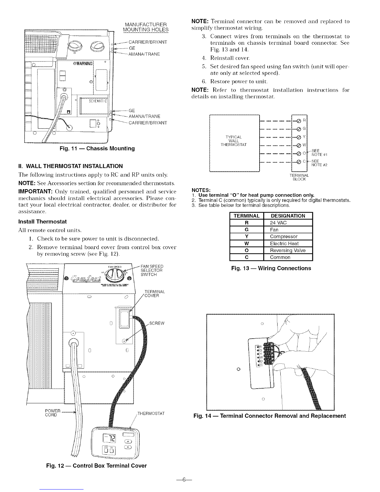
F. Fan Speed Control for Wall Thermostat Models
For maxinmm comfort, fat] speed is user selectable at the
unit. See Fig. 18.
CARE AND MAINTENANCE
In order to maintain proper performance of your packaged
terminal air conditioner or heat pump, it is very important
that the fat] and outdoor coil, the blower wheel, blower scroll,
electric heateL and all drain passages are thoroughly
cleaned at least once per year. Manufacturer i'ecommends
nlinimumly, cleaning should be conducted prior to the start
of each heating season. The air inlet filters should be cleaned
every month.
Depending on local conditions, more fi'equent cleaning of the
unit may be required to ensure optinmm performance and
long operating life. Examples of these special conditions
include areas where construction dust or heavy airborne dirt
is found, or enviromnents that promote the growth of fungus,
[[ H!>[ RA [kJkl m
M0[)I
OFF i
, ARHER COOLER EA I • COOL
Fig. 17 -- Standard Unit Controls
FAN SPEED
LO_
YuuRROOMIS EDUlPPED*ITHA _ALLtHERMOSTAt
kUJUSTFAN SPEEUHEREFO_ kUUEUC0MFO_r.
Fig. 18 --Wall Thermostat Control (Blank Plate)
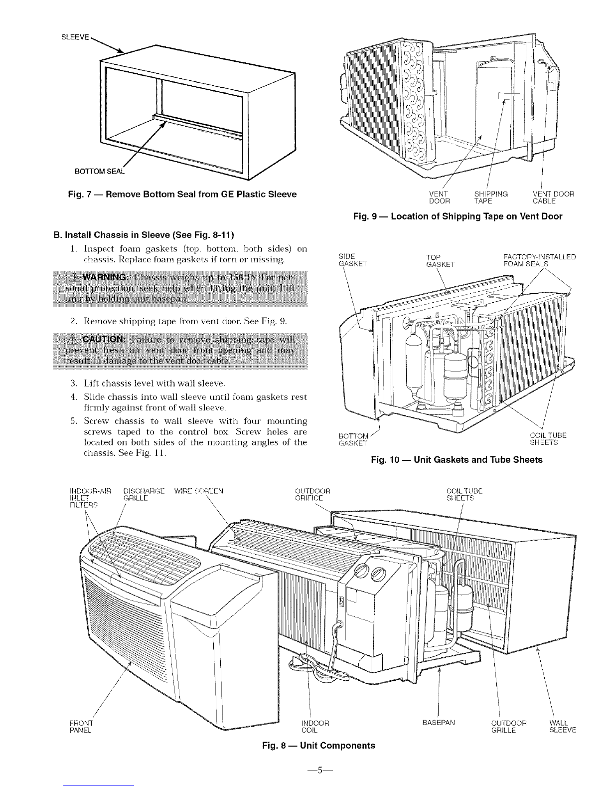
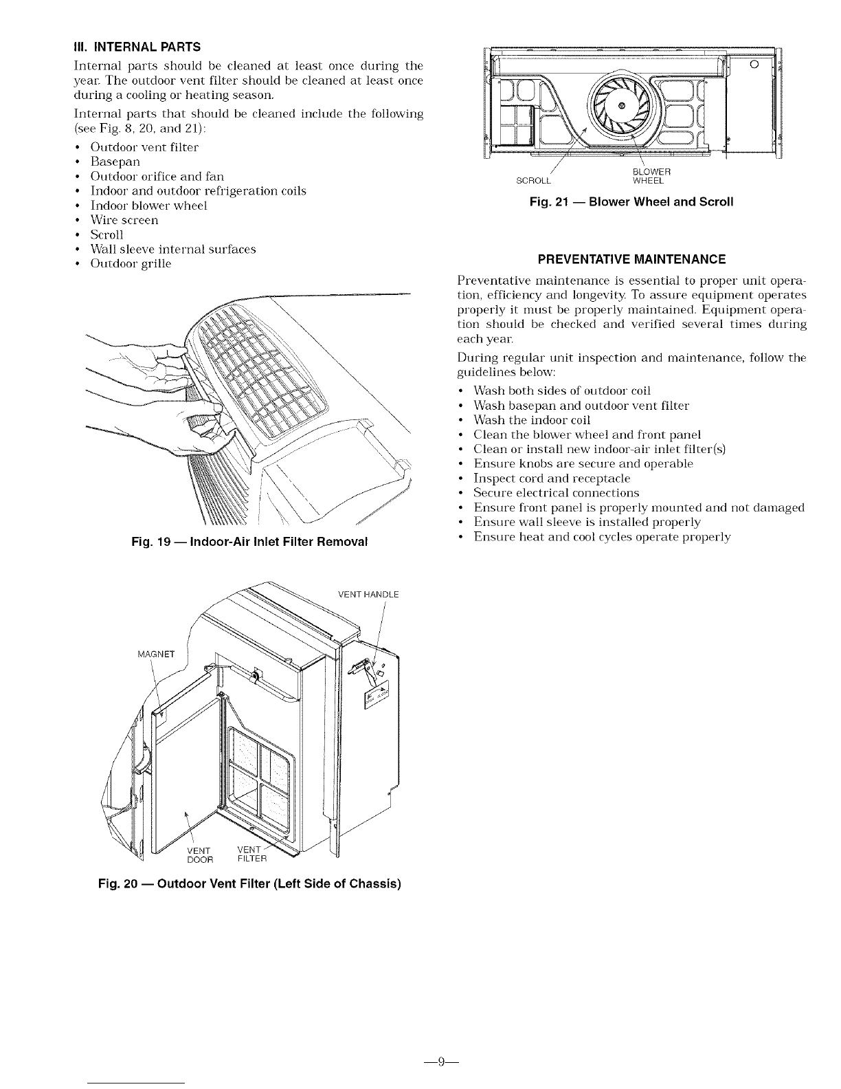
I. INDOOR-AIR INLET FILTERS
Indoor-air inlet filters should be cleaned once each month.
IMPORTANT: Filters may become clogged if not cleaned prop
erl3< Clogged filters will restrict airflow which may lead to
severe component damage and efficiency loss.
Cleaning Indoor-Air Inlet Filter
Two interchangeable air filters are located on the backside of
the front panel. Each can be removed and cleaned one at a
time. To remove and clean the filter, follow the steps below:
1, Grasp filter with both hands,
2. Gently pull the filter up and away from the unit. See
Fig. 8 attd 19.
3. To cleat] firm; use a vacuum or soft bristle brush with
a small amount of mild detergent.
NOTE: If detergent is used, remove any detergent residual
with a gentle stream of clean water
4. Allow filters to air dry
5. Re insert dry filters back into front panel.
Additional filters are available in multi-packs. Refer to
Accessories section.
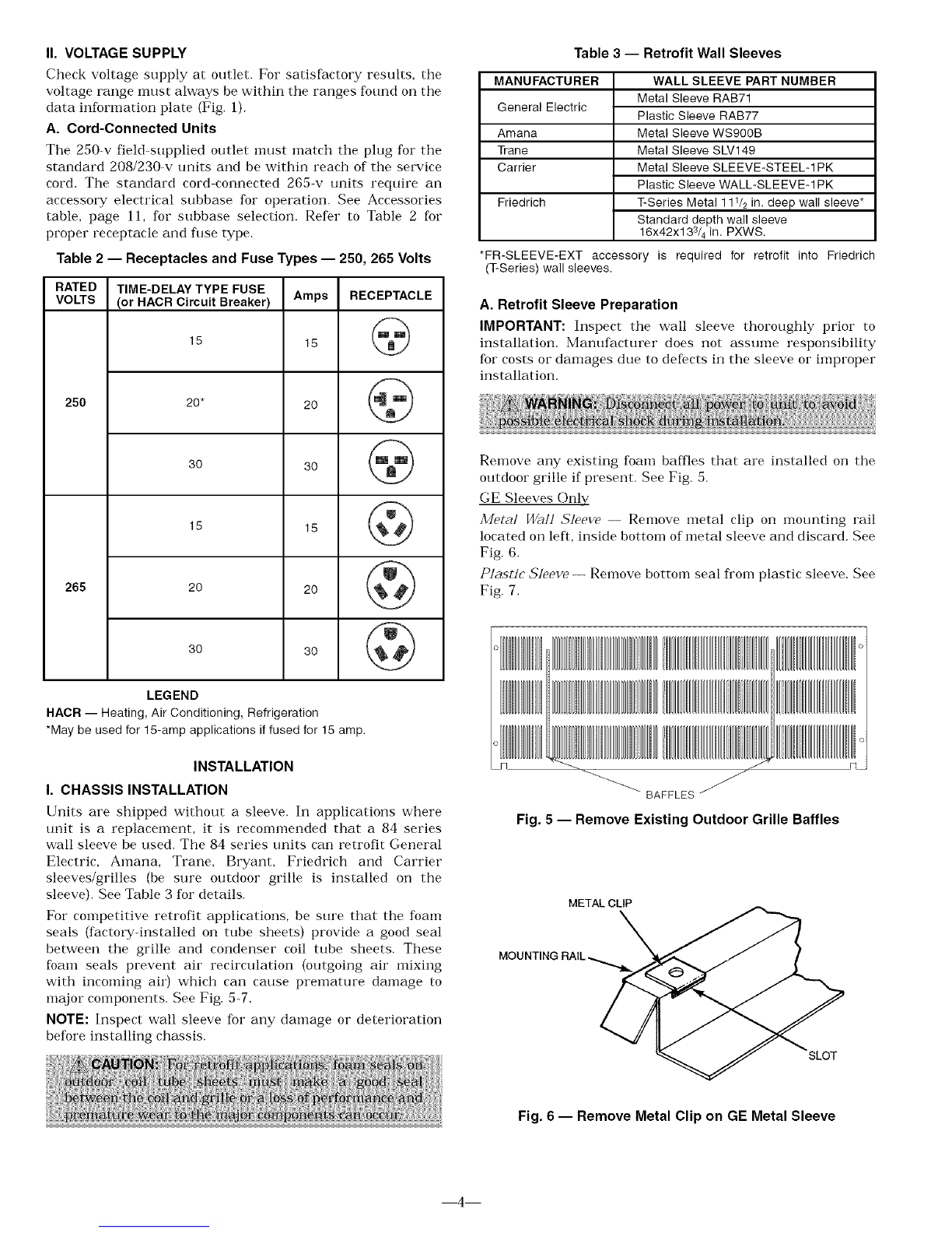
II. EXTERNAL PARTS
External parts include the polymer sleeve and grilles. The
sleeve manufacturer recommends cleaning the surface,
including the grilles, with household detergent and water
8

III. INTERNAL PARTS
Internal parts should be cleaned at least once during the
year. The outdoor vent filter should be cleaned at least once
during a cooling or heating season.
Internal parts that should be cleaned include the following
{see Fig. 8, 20, and 21):
• Outdoor vent filter
• Basepan
• Outdoor orifice and fan
• Indoor and outdoor refl'igeration coils
• Indoor blower wheel
• Wire screen
• Scroll
• Wall sleeve internal surfaces
• Outdoor grille
\
Fig. 19 -- Indoor-Air Inlet Filter Removal
/BLOWER
SCROLL WHEEL
Fig. 21 -- Blower Wheel and Scroll
PREVENTATIVE MAINTENANCE
Preventative maintenance is essential to proper unit opera-
tion, efficiency and longevity To assure equipment operates
properly it nmst be properly maintained. Equipment opera
tion should be checked and verified several times during
each year.
During regular unit inspection and maintenance, follow the
guidelines below:
• Wash both sides of outdoor coil
• Wash basepan and outdoor vent filter
• Wash the indoor coil
• Clean the blower wheel and front panel
• Clean or install new indoor-air inlet filter(s)
• Ensure knobs are secure and operable
• Inspect cord and receptacle
• Secure electrical connections
• Ensure fi'ont panel is properly mounted and not damaged
• Ensure wall sleeve is installed properly
• Ensure heat and cool cycles operate properly
VENT HANDLE
MAGNET
J
VENT VENT
DOOR FILTER
Fig. 20 -- Outdoor Vent Filter (Left Side of Chassis)
9

TROUBLESHOOTING
POSSIBLE CAUSES SOLUTIONS
UNIT DOES NOT START
Unit may have become unplugged •Check that plug is securely in wall receptacle.
Fuse may have blown • Replace the fuse. See Note 1.
Circuit breaker may have been tripped • Reset circuit breaker. See Note 1.
Unit mode dial may be set to the OFF position • Switch mode dial to an operating mode.
UNIT NOT COOLING/HEATING ROOM
Unit air discharge section is blocked
Temperature setting is not high or low enough
Unit air filters are dirty
Room is excessively hot or cold when unit is started
Vent door left open
UNIT MAKING NOISES
WATER DRIPPING OUTSIDE
WATER DRIPPING INSIDE
Wall sleeve is not installed level • Wall sleeve must be installed level for proper drainage of condensation. Check
that installation is level and make any necessary adjustments.
ICE OR FROST FORMS ON INDOOR COIL
Low outdoor temperature • When outdoor temperature is approximately 55 F or below, frost may form on
the indoor coil when unit is in Cooling mode. Switch unit to FAN operation until
ice or frost melts.
Dirty filters • Remove and clean filters.
NOTES:
• Make sure that curtains, blinds or furniture are not restricting or blocking unit
airflow.
• Reset to a lower or higher temperature setting.
• Remove and clean filters.
• Allow sufficient amount of time for unit to heat or cool the room. Start heating or
cooling early before outdoor temperature, cooking heat or gatherings of people
make room uncomfortable.
• Close vent door.
• Clicking, gurgling and whooshing noises are normal during operation of unit.
• If a drain kit has not been installed, condensation run-off during very hot and
humid weather is normal. See Note 2. If a drain kit has been installed and is
connected to a drain system, check gaskets and fittings around drain for leaks
and plugs.
1. If circuit breaker is tripped or fuse is blown more than once, contact a qualified electrician.
2. If unit is installed where condensation drainage could drip in an undesirable location, an
accessory drain kit should be installed and connected to drain system.
]0

ACCESSORIES
ACCESSORY
Wall Sleeves
Exterior Grillest
Subbase
Subbase
Field-Installed Kits
Electrical Connections
Condensate Drain Kit
Wall Thermostats
Wall Thermostat
Interface Retrofit Kit
FORM NUMBER
52S-48SI
52S-50SI
52S-49S1"
52C,P-20SI
52S-59SI
52S-58SI
52S-60SI
PART NUMBER
42-SLEEVE-1 PK
42-1NSUL-1PK
42-STEEL-1 PK
42-EXT24-1 PK
FR-SLEEVE-EXT
GRILLE-ALU-STAMP
GRILLE-PLA-BROWN
GRILLE-PLA-BEIGE
GRILLE-PLA-ALPIN
GRILLE-ALU-CLEAR
GRILLE-ALU-WHITE
GRILLE-ALU-BRONZ
GRILLE-ALU-MBRNZ
GRILLE-ALU-BROWN
GRILLE-ALU-BEIGE
GRILLE-ALU-ALPIN
GRILLE-ALU-PEACH
GRILLE-ALU-MELON
GRILLE-ALU-LGREY
GRILLE-ALU-SGREY
GRILLE-ALU-RDBRK
GRILLE-ALU-BLUE
52C,P-1SI
N/A
52C,P-2SI
DESCRIPTION
Non-Insulated Plastic Wall Sleeve, 1 per pack
Insulated Plastic Wall Sleeve, 1 per pack
Insulated Metal Wall Sleeve, 1 per pack
Extended Metal Wall Sleeve for Deep Wall Applications (24 in, deep), 1 per pack
Friedrich wall sleeve extension to retrofit PTAC unit into Friedrich 111/2-in. deep (T Series) wall
sleeve, 1 per pack
Stamped Aluminum Exterior Grille, Clear Finish
Plastic Architectural Rear Grille, Brown
Plastic Architectural Rear Grille, Beige
Plastic Architectural Rear Grille, Alpine
Aluminum Architectural Exterior Grille, Clear Finish
52C,P-3SI
52C,P-4SI
52C,P-5SI
52C,P-11SI
52C,P-19SI
52S-53SI
Aluminum Architectural Exterior Grille, White
Aluminum Architectural Exterior Grille, Light Bronze
Aluminum Architectural Exterior Grille, Medium Bronze
Aluminum Architectural Exterior Grille, Brown (Dark Bronze)
Aluminum Architectural Exterior Grille, Beige
Aluminum Architectural Exterior Grille, Alpine
Aluminum Architectural Exterior Grille, Peach
Aluminum Architectural Exterior Grille, Melon
Aluminum Architectural Exterior Grille, Light Grey
Aluminum Architectural Exterior Grille, Slate Gray
Aluminum Architectural Exterior Grille, Red Brick
Aluminum Architectural Exterior Grille, Blue
N/A
GRILLE-ALU-GREEN
SUBBASE-NON-ELEC
LEVELING-LEGS
SUBBASE-230_15A
SUBBASE-230_20A
SUBBASE-230_30A
SUBBASE-265_15A
SUBBASE-265_20A
SUBBASE-265_30A
SUBBASE-HARDWIRE
SUBBASE-SWITCH
SUBBASE-FUSE-15A
SUBBASE-FUSE-20A
SUBBASE-FUSE-30A
HARDWIRE-KI_IPK
CONDUIT-INTF-4PK
DRAIN-KIT-4PK
TSTATBBBAC01 -B
TSTATBBBHP01 -B
TSTATBB PAC01 -B
TSTATBBPHP01-B
RC-FIELDKIT230HC
RC-FIELDKIT230H P
52C,P-7SI RC-FIELDKIT265HC
RC-FIELDKIT265H P
TSTAT-COVE R-6X7
N/A
TSTAT-COVE R-7X 10
Replacement Filters N/A 84-FILTER-10PK
Energy Management 52C,P-10SI EM-KIT
Locking Security
Control Door 52C,P-13SI 84-SECURITY-DOOR
Lateral Duct Kit 52C,P-14SI
Power Fresh N/A
Air Vent
84-LATERAL-DUCT
PWR-VENT-DOOR230
PWR-VENT-DOOR265
52C,P-9Sl DEFLECTOR-1PK
Air/Curtain Deflector N/A 84-CURTDFL-1 PK
Touch-Up Paint N/A OEM-TOUCH-UP
*Extended metal wall sleeve also available in 26 in. and 28 in. depth,
tCustom colors are also available,
Aluminum Architectural Exterior Grille, Green
Non-electrical Subbase
Adjustable leveling legs for leveling and support when a subbase is not used,
Electrical subbase with factory-installed 208/230 V, 15 amp receptacle
Electrical subbase with factory-installed 208/230 V, 20 amp receptacle
Electrical subbase with factory-installed 208/230 V, 30 amp receptacle
Electrical subbase with factory-installed 265 V, 15 amp receptacle
Electrical subbase with factory-installed 265 V, 20 amp receptacle
Electrical subbase with factory-installed 265 V, 30 amp receptacle
Electrical subbase with factory-installed hardwire kit (230/208 V and 265 V)
Field-lnstallable Switch kit for an electrical subbase
Field-Installed Fuse Kit (18 amp) for electrical subbase
Field-Installed Fuse Kit (20 amp) for electrical subbase
Field-Installed Fuse Kit (30 amp) for electrical subbase
Permanent power connection to the unit (includes 36 in. of flexible conduit and Molex connector
for easy connect/disconnect, 230/208 V and 265 V) 1 per pack
Interface kit for field-supplied conduit includes Molex connector for easy connect/disconnect. 4
per pack
Attaches to wall sleeve for controlled internal or external disposal of condensate 4 per pack
Builder's Model Electronic Thermostat w/Digital display (Heat/Cool Models)
Builder's Model Electronic Thermostat w/Digital display (Heat Pump Models)
7-Day Programmable Electronic Thermostat (Heat/Cool Models)
7-Day Programmable Electronic Thermostat (Heat Pump Models)
Field-installed wall thermostat retrofit kit to convert a standard 230 V Heat/Cool unit to an
RC unit. Wall thermostat sold separately (can be used to convert a cool only unit to RC).
Field-installed wall thermostat retrofit kit to convert a standard 230 V Heat Pump unit to an
RC unit. Wall thermostat sold separately.
Field-installed wall thermostat retrofit kit to convert a standard 265 V Heat/Cool unit to an
RC unit. Wall thermostat sold separately (can be used to convert a cool only unit to RC).
Field-installed wall thermostat retrofit kit to convert a standard 265 V Heat Pump unit to a
RC unit. Wall thermostat sold separately.
Clear plastic locking thermostat cover prevents unauthorized access to thermostat. Cover for
use with non-programmable and electro-mechanical thermostats. Outside dimensions: 61/2 in. x
71/2 in. x 21s/16inch. 1 per pack.
Clear plastic locking thermostat cover prevents unauthorized access to thermostat. Cover for
use with programmable thermostats. Outside dimensions: 71/4 in. x 93/4 in. x 33/8 inch.
1 per pack
Replacement air filters in package of 10
Allows unit to be turned on and off from a remote location (includes freeze guard protection)
Key-locking security door to prevent access to heating and cooling controls
Ductwork to allow one unit to heat and cool two rooms (plenum plus extension duct and
registers)
Power vent with automatic door that opens and closes when the fan turns on and off.(208/230 V)
Power vent with automatic door that opens and closes when the fan turns on and off. (265 V)
Lateral air deflector, with individually adjustable louvers, to enhance air circulation, 1 per pack
Curtain deflector -- prevents curtains from blowing into discharge airstream. 1 per pack
Touch up paint for repainting scratches or chips.
]]

c)
o
8
c)
o
Co
[:3
q3
C)
S
5_
Z
P
co
4_
,b
84 Series
Packaged Terminal
Air Conditioner Warranty
FULL ONE-YEAR WARRANTY -- During the first year after purchase, CAC/BDP
will, through its authorized independent servicing dealers or service stations*, and
free of charge to the user or subsequent users, repair or replace any parts which
are defective in material or workmanship. The replacement part can be a new or
remanufactured part as provided at CAC/BDP's sole option.
FULL EXTENDED FOUR-YEAR WARRANTY ON SEALED REFRIGERATION
SYSTEM ONLY -- During the second through fifth years after date of original pur-
chase, CAC/BDP will, through its authorized servicing dealers and service stations*
and free of charge to the end user or subsequent users, repair or replace the
compressor condenser, evaporator or connecting tubing if defective in material or
workmanship. This includes system refrigeration charge. The replacement part can
be new or a remanufactured part as provided at CAC/BDP's sole option.
LIMITED EXTENDED FOUR-YEAR WARRANTY ON NON-SEALED REFRIGER-
ATION SYSTEM ONLY -- During the second through fifth years after date of origi-
nal purchase, CAC/BDP will, through its authorized servicing dealers and service
stations and free of charge to the end user or subsequent users, repair or replace
any non-sealed system part (motor, solenoid, thermistor, thermostat, relays, switch,
capacitor, overload, drain valve, bulb heater, fan, stator) if defective in material or
workmanship. The replacement part can be new or a remanufactured part at
CAC/BDP's sole option. THIS LIMITED WARRANTY DOES NOT INCLUDE
LABOR, user is responsible for labor, including cost of diagnosis of problem,
removal and transportation of the air conditioner to and from the service center, and
reinstallation charges necessary to accomplish repair.
LIMITATION OF WARRANTIES -- ALL IMPLIED WARRANTIES (INCLUDING
IMPLIED WARRANTIES OF MERCHANTABILITY) ARE HEREBY LIMITED IN
DURATION TO THE PERIOD FOR WHICH EACH LIMITED WARRANTY IS GIVEN
AND APPLIES. SOME STATES DO NOT ALLOW LIMITATIONS ON HOW LONG
AN IMPLIED WARRANTY LASTS, SO THE ABOVE LIMITATION MAY NOT APPLY
TO YOU. THE EXPRESSED WARRANTIES MADE IN THIS WARRANTY ARE
EXCLUSIVE AND MAY NOT BE ALTERED, ENLARGED, OR CHANGED BY ANY
DISTRIBUTOR, DEALER, OR OTHER PERSON WHATSOEVER.
ALL WORK UNDER THE TERMS OF THIS WARRANTY SHALL BE PERFORMED
DURING NORMAL WORKING HOURS. ALL REPLACEMENT PARTS, WHETHER
NEW OR REMANUFACTURED, ASSUME AS THEIR WARRANTY PERIOD ONLY
THE REMAINING TIME PERIOD OF THIS WARRANTY.
CAC/BDP WILL NOT BE RESPONSIBLE FOR:
1. CLEANING REQUIRED PRIOR TO WARRANTY REPAIR.
2. Standard maintenance, cleaning or damage resulting from failure to perform
normal maintenance as outlined in the ownei_s manual,
3, Instruction on methods of control and use of air conditioning unit after initial
installation,
4. Damage or repairs needed as a consequence of faulty installation or applica-
tion, This is the responsibility of the installer.
5. Failure to start due to voltage conditions, blown fuses, open circuit breakers
or any other damages due to the inadequacy or interruption of electrical
services.
6, Damage or repairs needed as a consequence of any misapplication, abuse,
unauthorized alteration, improper servicing or operation,
7. Damage as a result of floods, winds, fires, lightning, accidents, corrosive
environment, or other conditions beyond the control of CAC/BDR
EXCEPTION TO CORROSIVE ENVIRONMENT IN ABOVE PARAGRAPH --
Packaged terminal units (84 Series) built with corrosion protection are exempt
from the exclusion -- "Corrosive Environment." The unit model number is
identified on the nameplate with a CP or RP suffix.
8, Reimbursement for replacement parts or repair services which are not sup-
plied or designated by CAC/BDP and which are specifically covered under
this warranty
9. CAC/BDP products installed outside the continental U.S.A,, Alaska, Hawaii
and Canada.
10. Shipping damage or damage as a result of transporting the unit, This is the
responsibility of the selling dealer or the authorized Room Air Conditioner
service station.
11, ANY SPECIAL, INDIRECT OR CONSEQUENTIAL PROPERTY OR COM-
MERCIAL DAMAGE OF ANY NATURE WHATSOEVER. Some states do not
allow the exclusion or limitation of incidental or consequential damages, so
the above limitation or exclusion may not apply to you,
12. Warranty coverage of accessory items (wall thermostats, wall sleeves, etc.).
NOTE: Service and Maintenance items excluded in this warranty may be covered by
a separate service agreement through the seller at time of purchase.
*Authorized independent dealers or service stations are registered with CAC/BDP Air Conditioning through its distributor organization. Please call toll-free 1-877-875-3362 for
a local dealer.
This warranty gives you specific legal rights, and you may also have other rights which vary from state to state.
Catalog No. 530-122 (Rev. 3/02)
This manual suits for next models
1
Table of contents
Other ICP Air Conditioner manuals
Popular Air Conditioner manuals by other brands

Be Cool
Be Cool BCP5AC2101F manual

McQuay
McQuay MCK020A Technical manual

Toshiba
Toshiba RAC-PD0811CRU user manual

Mitsubishi Electric
Mitsubishi Electric MSC-GE20VB operating instructions

Haier
Haier AB052MAERA Operation & installation manual

Mitsubishi Electric
Mitsubishi Electric Mr. Slim PUZ-M200YKA2.UK Service manual