Wiring
INPUT WIRING: maximum distance of 300m (1000ft)
from the System Controller when using 22 AWG.
AUX WIRING: Min 22AWG Max 16AWG. (Depends on
length and Current consumption). For wire/cable size,
a maximum of 5% voltage drop at the terminals of
the powered device has to be observed.
MODULE NETWORK WIRING: Recommended Belden
9842 or equivalent. (24AWG twisted pair with
characteristic impedance of 120ohm or CAT5e / CAT6
are also supported for Data Transmission when using
ground in the same cable. (Do not use extra wires to
power devices.) Max 900m (3000ft).
LED Description
Incorrect module input voltage applied.
Module successfully registered with controller.
Module attempting registration with controller
Module communication activity.
Red
Number of Flashes Error Description
Input is in the TAMPERED state.
Input is in the SHORTED state.
Please refer the System Controller Installation Manual for address programming details.
The address of the Input Expander is configured via programming and will require reference
to the module serial number. The serial number can be found on the identification sticker on the
side of the module.
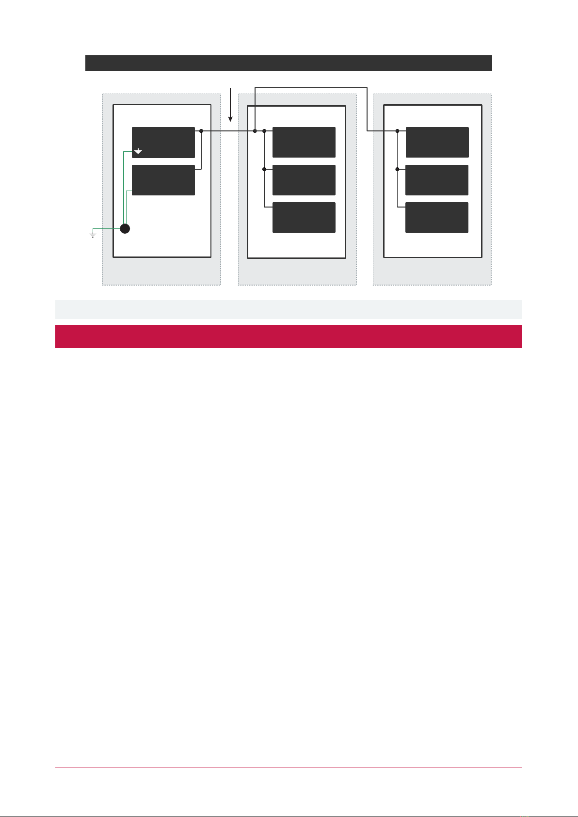
BN-
N+N AN
System Controller or
module supplying
power to networked
devices
Next modules
on network
BN-N+N AN
White
Blue
Black
Red
Input Expander
CAUTION: INCORRECT
WIRING MAY RESULT IN
DAMAGE TO THE UNIT
Value 1 Value 2 Monitored Status
1K 1K Open, Close, Tamper, Short
6K8 2K2 Open, Close, Tamper, Short
10K 10K Open, Close, Tamper, Short
2K2 2K2 Open, Close, Tamper, Short
4K7 2K2 Open, Close, Tamper, Short
4K7 4K7 Open, Close, Tamper, Short
4Z
3Z
2
Z M
O
C
MO
C
1Z-
X
UA
+
N.C
Tamper
N.C Input Contact
Value 2 Value 1
Typical Input Circuits
EOL Resitor Input Configuration
Address Configuration
Correct module input voltage applied.
Power
Status
Green
Off
Fault
Input 1-8
Module is in boot mode awaiting firmware update
Single Red flash
Slow Green flashing
Fast Green flashing
Slow Red flashing
Module is in error state. Error code is displayed by flashing the Red
Status indicator ON and OFF rapidly, with a delay of 1.5 second
between each display cycle.
Red flashing
Green flashing
Green
For further details, please refer to the Error Code Display section in the Installation Manual.
Input is in the CLOSED state.
Input is in the OPEN state.
Input is not programmed.
Off
Locked Device
1
7
Serial Number Fault
6
5Controller Secured
4Address in Use
3Address Too High
2Firmware Version
Unknown Error Code
Red