Protege DIN Rail 8 PGM Output Expander | Installation Manual 3
Contents
1Introduction_______________________________________________________________ 5
2Installation Requirements___________________________________________________ 6
3Grounding Requirements ___________________________________________________ 7
3.1Safety Grounding ..........................................................................................................7
3.2Earth Ground Connection..............................................................................................7
4Mounting _________________________________________________________________ 9
4.1Removal.........................................................................................................................9
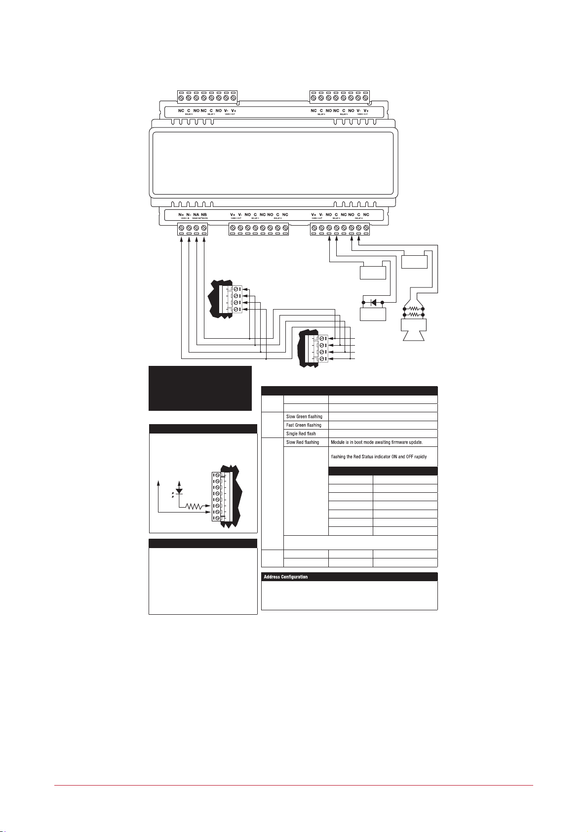
4.2Wiring Diagram............................................................................................................10
5DC Power & Encrypted Module Network ____________________________________ 11
6Outputs _________________________________________________________________ 12
6.1PGM Outputs 1 to 8 ....................................................................................................12
7Address Configuration ____________________________________________________ 13
8LED Indicators ___________________________________________________________ 14
8.1Status Indicator ...........................................................................................................14
8.2Fault Indicator..............................................................................................................14
8.3Power Indicator ...........................................................................................................14
8.4Output Indicators.........................................................................................................15
9Error Code Indication _____________________________________________________ 16
9.1Error Code Display ......................................................................................................16
10Mechanical Diagram ______________________________________________________ 17
11Mechanical Layout _______________________________________________________ 18
12Technical Specifications___________________________________________________ 19
13New Zealand and Australia ________________________________________________ 20
14European Standards ______________________________________________________ 21
15UL and ULC Installation Requirements ______________________________________ 23
15.1UL/ULC Installation Cabinet Options ..........................................................................23
15.2ULC Compliance Requirements..................................................................................23
CAN/ULC-S304-06......................................................................................................23
CAN/ULC-S319-05......................................................................................................26