manuals.online logo
Brands
  1. Home
  2. •
  3. Brands
  4. •
  5. Advantech
  6. •
  7. Extender
  8. •
  9. Advantech IMC-150LPI Installation and operation manual

Advantech IMC-150LPI Installation and operation manual

1 Startup Manual
c
IMC-150LPI
Long Reach PoE+ Extender
Injecting data and power together, the IMC-150LPI is
brand new leading product which break the 100
meters limitation to greater Ethernet transmission
distances. Supports 10/100Mbps Ethernet over
twisted pair cable (CAT-5, UTP).
Provides user configurable DIP switch selection of
LFPT feature and force speed setting. Flexible and
freely extends existing Ethernet networks to reach
remote IP devices.
The IMC-150LPI PoE+ extender compliant with
IEEE 802.3at PoE+ standard, it delivers data and
power over Ethernet cable without the distance
limitations of traditional copper wires. Extends data
and power transmission reach up to 800 meters. Also
acting as both power sourcing equipment(PSE) and
powered device (PD), power source from PoE+
switch or power with 48VDC input to either local or
remote sites.
Before installation, please make sure that you have
received the following:

1 x IMC-150LPI PoE+ extender

1 x Wall-mount kit

1 x Din-rail

Startup Manual
If anything is missing or damaged, contact your
distributor or sales representative immediately.
The Startup manual and product data sheet can be
download on the Advantech's website.

Compatibility: IEEE 802.3, 802.3u, 802.3x,
802.3at/af

LAN: 10/100Base-T(X)

Connectors:
- 1 x 10/100Mbps RJ-45 PD
- 1 x 10/100Mbps RJ-45 PSE

LED Indicators: PWR, 1-PAIR, PSE

DIP Switch: LFPT, AUTO-Nego, Speed

Power:
-
Power Consumption: Max. 33 W
(Full load PoE+)
-
Power Input: 48V DC
-
Power Output 30W
-
Connectors: 2P Pluggable Terminal Block,
DC Jack

Dimensions (W x H x D):
92.58 x 21.08 x 98.04 mm (3.65 x 0.83 x 3.86 in.)

Enclosure: IP30

Operating Temperature: -40 ~ 75°C (-40~167°F)

Storage Temperature: -40 ~ 80°C (-40 ~ 176°F)

Humidity: 0 ~ 95% (non-condensing)

Railway Trackside: EN 50121-4

EMC: CE, FCC
Front Panel View
Top Panel View
Rear Panel View
Packing List
Datasheet Do uments
STARTUP MANUAL
Notes
For more information on this and other Advantech
products, please visit our websites at:
http://www.advantech.com/products
For technical support and service:
http://www.advantech.com/support/
This startup manual is for IMC-150LPI
P/N: 2049150L00
1st Edition
August, 2019
Overview Specifications
Panel View
Startup Manual 2
The wall-mount kit should be already be fixed to the
back panel of the IMC-150LPI. iI you need to attach
the attachment plate, follow the steps as show in the
figures below.
1.
Loosen the screw and reverse the direction of the
attachment wall-mount kit.
2.
Tightening the wall-mount kit with 2 screws
1.
Installing the DIN-Rail Mounting Kit.
2.
Removing the DIN-Rail.
3.
Once the screws are fixed in the wall, insert the
screw heads then slide the IMC-150LPI. Make
sure the IMC-150LPI is tighten stability on the
wall.
The terminal block connector is used for
IMC-150LPI AC/DC inputs. See below figures for
wiring the redundant power.
1.
Insert the positive and negative wires into the
V+/V- contacts on the terminal block connector.
2.
Tighten the wire-clamps screws to prevent the DC
wires coming loose.
Warning: This is a Class A product. In domestic
environment this product may cause radio
interference in which case the user may be required
to take adequate measures.
Avertissement: Ceci est un produit de classe A.
Dans un environnement domestique, ce produit peut
provoquer des interférences radio, auquel cas
l'utilisateur peut être tenu de prendre les mesures
adéquates.
Warning: 1) an UL Listed Class II power adapter
suitable for use at Tma 50 degree C whose output
meets ES1 (or SELV), PS2 (or LPS) and is rated
48VDC 1.36A min., or 2) an UL Listed Class II DC
power source suitable for use at Tma 85 degree C
whose output meets ES1 (or SELV), PS2 (or LPS)
and is rated 48VDC, 1.36A min.
Avertissement: 1) un adaptateur secteur de classe II,
répertorié UL, approprié pour une utilisation à 50
degrés Celsius, dont la sortie est conforme aux
normes ES1 (ou SELV), PS2 (ou LPS) et une tension
nominale de 48Vcc 1.36A min. ou 2) une source
d'alimentation CC de classe II répertoriée UL
pouvant être utilisée à une température de 85 degrés
Celsius dont la sortie est conforme à ES1 (ou SELV),
PS2 (ou LPS) et d'une puissance nominale de 48Vcc,
1.36A min
Wall Munting
Din-rail Mounting (Optional Accessory)
Power Connection
3 Startup Manual
n
The default setting for each DIP switch is ON. Please
see the following table for detail configuration.
DIP Switch
Name
Setting
Description
PIN 1
LFPT
ON LFPT feature enabled. The default value.
OFF LFPT feature disabled.
PIN 2
AUTO
ON Auto‐Nego enabled. The default value.
OFF
Auto‐Nego disabled and change to force
speed. Configure PIN 3 to select
connection speed.
PIN 3
SPEED
ON 100Mbps The default value.
OFF 10Mbps
PIN 4
Reserve for future use.
The LED definition is described in the table below.
1.
PoE Pass-Through
2.
Local PoE Injection
3.
Remote PoE Injection
1.
Set LFPT function and data rate via DIP Switch
Keep the default values on the device, or locate the
LFPT function or data rate via DIP switches.
Note: The data rate should be configured the same
on both local and remote side.
2.
Connect P2/PSE as extended port with local
unit
Connect the port 2 (PSE) for extended distance
transmission with local unit.
3.
Connect P1/PD as extended port with remote
unit
Connect the port 1 (PD) for extended distance
transmission with remote unit.
Note: The PoE could be only available in 2-pair
mode.
4.
Connect Ethernet Network
Wiring CAT5/5e cable to connect Local unit to
PoE switch or network and Remote unit to PD
device.
5.
Connect the power
Power input through the followings:
-
Local Power: 48VDC input via DC Jack or
48~55VDC via terminal block
-
PoE Pass-Through: Powered by PoE switch,
no external power required.
-
PoE Injection: 48~55VDC
DIP Switch Settings Installation Diagram
ATTENTION:
Make sure the AC/DC power source
voltage is stable, and do not plug the
IMC-150LPI via the same power source
to avoid generating power circuit
looping damage.
LED Color State Description
PWR
Green
ON
Multiple power input. DC jack,
terminal block and PD.
OFF No powered.
1‐PAIR
Green
ON When link with 1‐PAIR cable.
OFF When link with 2‐PAIR cable.
PSE
Green
ON When PoE PSE works.
OFF No works.
P1/PD
10M LNK/ACT
Green
ON Link / active at 10Mbps
OFF No link.
P1/PD
100M LNK/ACT
Green
ON Link / active at 100Mbps
OFF No link.
P2/PSE
10M LNK/ACT
Green
ON Link / active at 10Mbps
OFF No link.
P2/PSE
100M LNK/ACT
Green
ON Link / active at 100Mbps
OFF No link.
LED Indicators
Installation Instructio s
Startup Manual 4
IMC-150LPI Data Range
RATE UTP 1-PAIR UTP 2-PAIR
10Mbps 800m 250m
100Mbps 300m 500m
IMC-150LPI PoE Ragne
Power Souce
(Watts)
10Mbps 100Mbps
PD PoE Class 2
(6.5W)
800m 500m
PD PoE Class 3
(13W)
300m 300m
PD PoE Class 4
(22W)
200m 200m
Local Power
Injection 30W
100m 100m
Approximate Maximum Extended
Distances
NOTE:
The extended distances figures are
based on a 48VDC external power
input and 50V PSE PoE power
source. Transmission distances and
power could be influenced by factors
such as cable quality, the number of
connectors and environmental
conditions.
PoE over extended distance is only
available in 2-PAIR mode.

Other Advantech Extender manuals

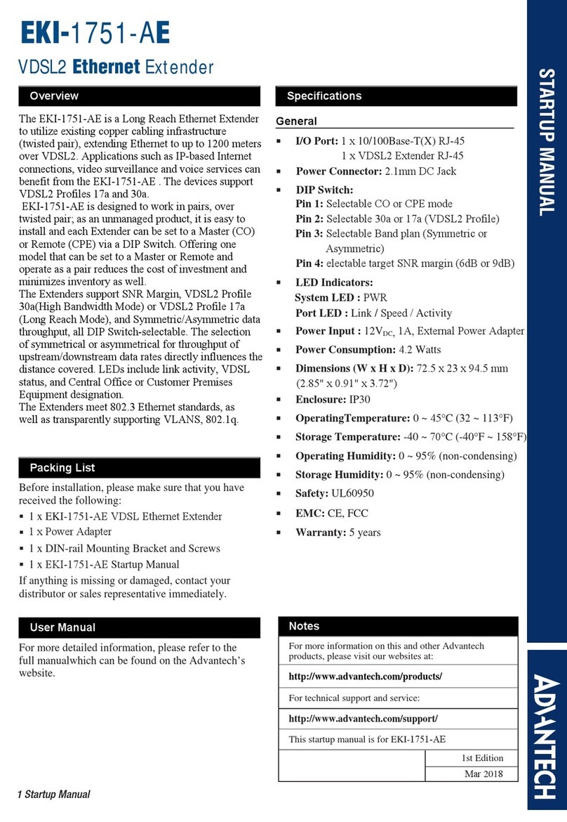
Advantech EKI-1751-AE User manual

Advantech

Advantech EKI-1751-AE User manual

Advantech EKI-1751I User manual

Advantech

Advantech EKI-1751I User manual

Advantech EKI-1751-AE Installation and operation manual

Advantech

Advantech EKI-1751-AE Installation and operation manual

Advantech EIS2-EXTEND-A User manual

Advantech

Advantech EIS2-EXTEND-A User manual

Advantech EKI-1751PI-M-AE User manual

Advantech

Advantech EKI-1751PI-M-AE User manual

Advantech EKI-2701MPI-R Installation and operation manual

Advantech

Advantech EKI-2701MPI-R Installation and operation manual

Advantech VEGA-1000 User manual

Advantech

Advantech VEGA-1000 User manual

Popular Extender manuals by other brands

Schumacher PROBOOSTER DSR103 owner's manual

Schumacher

Schumacher PROBOOSTER DSR103 owner's manual

Commodore ARM2SID Quick installation guide

Commodore

Commodore ARM2SID Quick installation guide

TP-Link Deco P7 user guide

TP-Link

TP-Link Deco P7 user guide

Cudy RE750 Quick installation guide

Cudy

Cudy RE750 Quick installation guide

Gefen EXT-VGAKVM-LAN user manual

Gefen

Gefen EXT-VGAKVM-LAN user manual

Amped Wireless TAP-EX2 Setup guide

Amped Wireless

Amped Wireless TAP-EX2 Setup guide

BeingHD HDBT-4K60-40TR user manual

BeingHD

BeingHD HDBT-4K60-40TR user manual

SureCall Force7 Industrial user guide

SureCall

SureCall Force7 Industrial user guide

Gefen CAT5-5000HD Specifications

Gefen

Gefen CAT5-5000HD Specifications

Enable-IT 865Q PRO quick start guide

Enable-IT

Enable-IT 865Q PRO quick start guide

AVARRO 0E-HDMIEX4KA manual

AVARRO

AVARRO 0E-HDMIEX4KA manual

Lindy 43308 user manual

Lindy

Lindy 43308 user manual

Solutions MS-6U1C user guide

Solutions

Solutions MS-6U1C user guide

Techly IDATA HDMI-WL53 quick start guide

Techly

Techly IDATA HDMI-WL53 quick start guide

Icron USB 2.0 RG2304SP quick start guide

Icron

Icron USB 2.0 RG2304SP quick start guide

Jaycar Electronics AC1736 user manual

Jaycar Electronics

Jaycar Electronics AC1736 user manual

SureCall N-Range user guide

SureCall

SureCall N-Range user guide

Extron electronics PowerCage FOX HDMI Setup guide

Extron electronics

Extron electronics PowerCage FOX HDMI Setup guide

manuals.online logo
manuals.online logoBrands
  • About & Mission
  • Contact us
  • Privacy Policy
  • Terms and Conditions

Copyright 2025 Manuals.Online. All Rights Reserved.