-
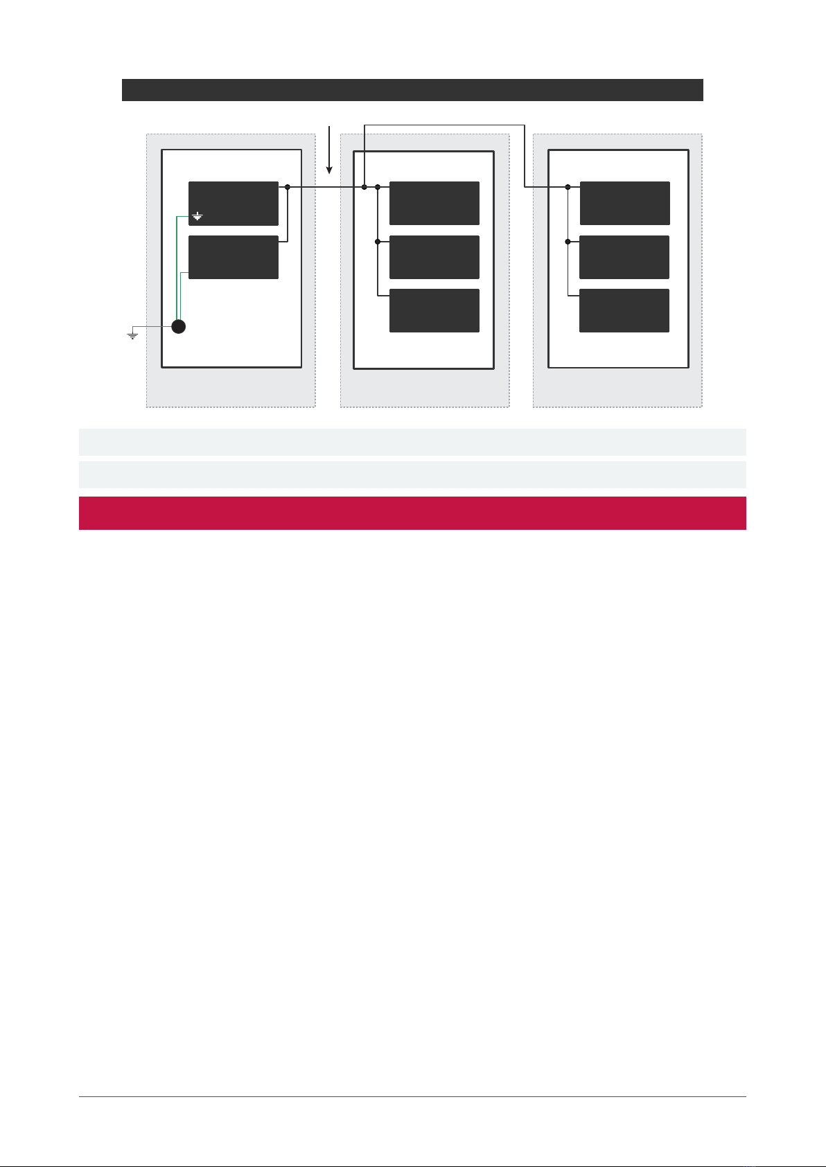
Electric Locking
Device
Power Supply
Power Supply
Wiring
AUX WIRING: Min 22AWG Max 16AWG.
(Depends on length and current consumption).
For wire/cable size, a maximum of 5% voltage drop at
the terminals of the powered device has to be observed.
MODULE NETWORK WIRING: Recommended
Belden 9842 or equivalent. 24AWG twisted pair with
characteristic impedance of 120ohm or CAT5e / CAT6
are also supported for data transmission when using
ground in the same cable. Max 900m (3000ft).
Do not use extra wires to power devices.
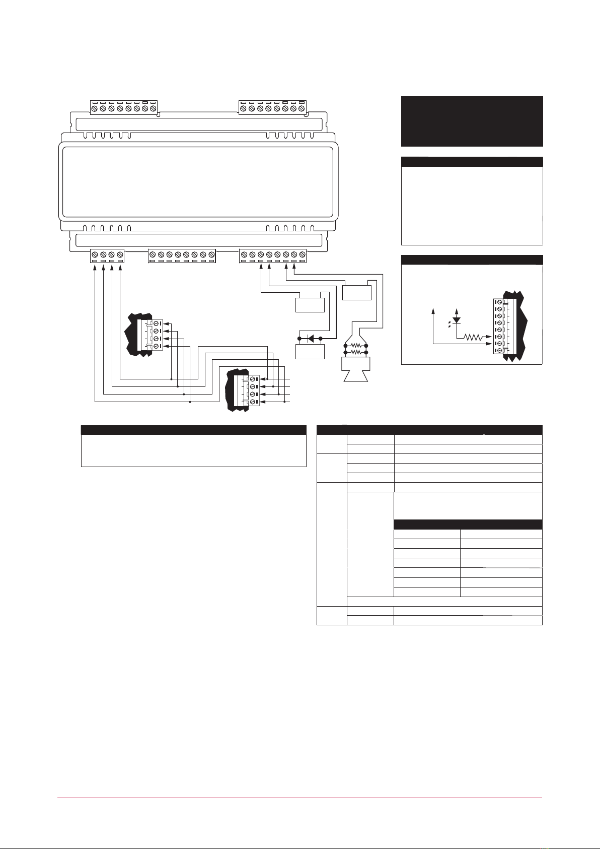
Outputs 1-8
Address Configuration
The module address is configured via programming and will require reference to the
module serial number. The serial number can be found on the identification sticker on the
side of the module.
Please refer to the system controller configuration guide for address programming details.
Error Description
Description
Firmware Version
Output is OFF.
LED
Module successfully registered with controller.
Module attempting registration with controller.
Module communication activity.
Number of Flashes
For further details, refer to the Error Code Display section in the installation manual.
Address Too High
Address in Use
Controller Secured
Serial Number Fault
Locked Device
Output is ON.
Red
Incorrect module input voltage applied.
Power
Status
Green
Off
Red
Error code is displayed by flashing the red Status Indicator ON
and OFF rapidly with a delay of 1.5 seconds between each cycle.
Fast green flashing
Correct module input voltage applied.
Slow green flashing
Module is in boot mode awaiting firmware update.
Fault
1
Output 1-8
Single red flash
Slow red flashing
Unknown Error Code
2
3
4
5
6
7
Off
Module is in error state.
The 8 outputs each have a Form C relay. These
outputs can be used to activate bell sirens, lighting
circuits, door locks, relay accessory products
and other automation points.
V+ V- NO C NC NO C NC
0V +12V AUX
LED
1k5 OHM
NAN+ N- NB
System controller or module
supplying power to networked
devices
Next modules
on network
NAN+ N- NB
White
Blue
Black
Red
NO
RELAY 5 12VDC OUT
CNCC V+V-
Output Expander
+
-
+
-
+
-
8 Ohm 30W
Siren or 1.1A
(Typical)
1k
+
NONC
RELAY 6
NO
RELAY 7 12VDC OUT
CNCC V+V-
NONC
RELAY 8
NO
RELAY 3
12VDC OUT
NCC
V- NC
C
NO
V+
RELAY 4
NO
RELAY 1
12VDC OUT
NCC
V- NC
C
NO
V+
RELAY 2
RS485 NETWORK12VDC IN
NBN- NAN+
CAUTION: INCORRECT
WIRING MAY RESULT IN
DAMAGE TO THE UNIT