V+ V- NO V4 V5 V6 V7 V8Z1 Z2 Z3 Z4 Z5 Z6 Z7 Z8
Blue
Red
Black
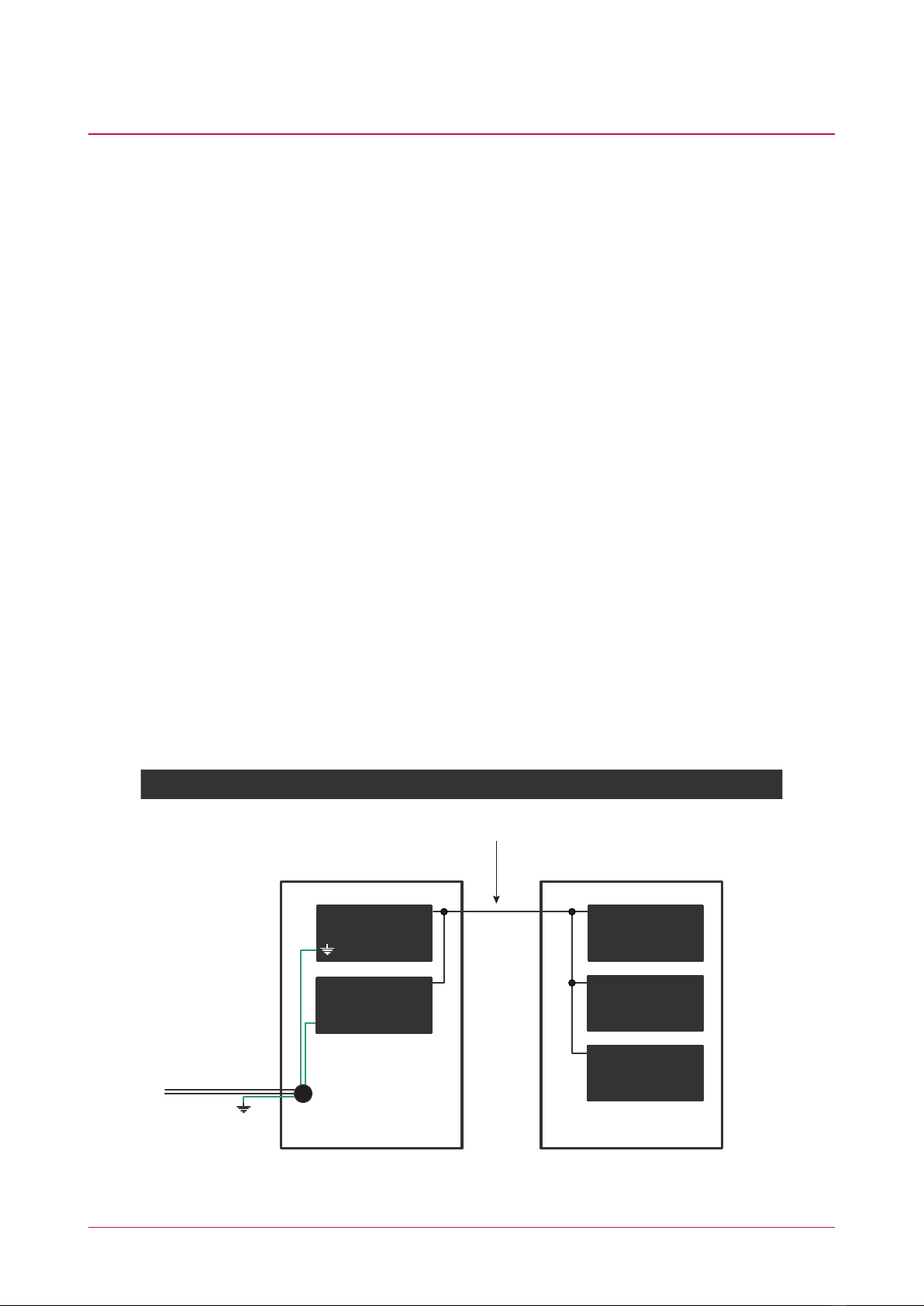
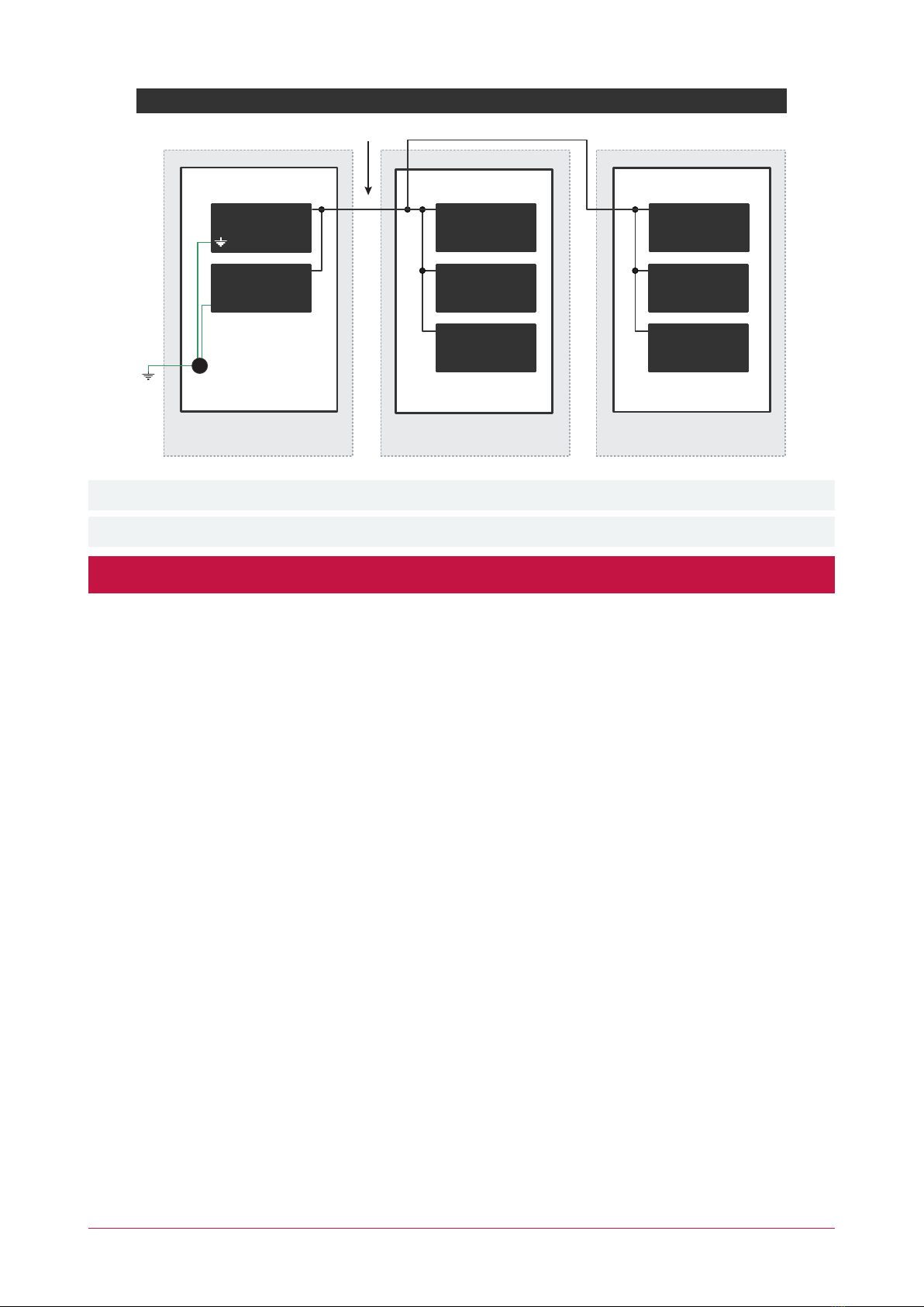
Next modules
on network
System controller or
module supplying
power to networked
devices
White
Reader Expander
Value 2
Typical Input Circuits
Outputs
N.C Input Contact
N.C Tamper
Value 1
DescriptionFunction
2 Beeps Access Granted
1 Long Beep Access Denied
4 Beeps Offline Access Granted
+12V AUX
LED
1k5 OHM
Example Open Collector Output Connection (LED)
V+ V- DO L2D1 L1 BZ C
Description
Output Number
Yellow
Shield
Red
Black
Green
White
Brown
Orange
Blue
12VDC IN
N-N+
Z8 Z7 Z6 Z5 Z4 Z3 Z2 Z1
DOOR1
REX1
SENSE1
REN1
DOOR2
REX2
SENSE2
REN2
D0/
READER 2
D1/
L1
BZ V+
V-
L2
C
12VDC OUT
RS485 NETWORK
NBNA NA
READER 1
NB
D1/ L1 BZV+
V-
L2 C
12VDC OUT
D0/
NB NA
Address Configuration
The module address is configured via programming and will require reference to the
module serial number. The serial number can be found on the identification sticker on the
side of the module.
Please refer to the system controller configuration guide for address programming details.
Error Description
Description
LED
Power Green
Off
Firmware Version
Data received but format is incorrect.
Module successfully registered with controller.
Module attempting registration with controller.
Module communication activity.
Number of Flashes
For further details, refer to the Error Code Display section in the installation manual.
Address Too High
Address in Use
Controller Secured
Serial Number Fault
Locked Device
Correctly formatted data received.
Long green flash
Incorrect module input voltage applied.
Status
Red
Error code is displayed by flashing the red Status Indicator ON
and OFF rapidly with a delay of 1.5 seconds between each cycle.
Fast green flashing
Correct module input voltage applied.
Slow green flashing
Module is in boot mode awaiting firmware update.
Fault
1
Reader 1/2
Single red flash
Slow red flashing
Unknown Error Code
2
3
4
5
6
7
Short green flash
Module is in error state.
Relay is closed.
Relay is open.
Off
Relay 1/2
Red
Input is not programmed.
Input is in the OPEN state.
Red
Off
Input is in the CLOSED state.
Input is in the TAMPERED state.
Red flashing
Input 1-8 Green
Input is in the SHORTED state.
Green flashing
Wiring
INPUT WIRING: maximum distance of 300m (1000ft)
from the Reader Expander when using 22 AWG.
AUX WIRING: Min 22AWG Max 16AWG.
(Depends on length and current consumption).
For wire/cable size, a maximum of 5% voltage drop at
the terminals of the powered device has to be observed.
MODULE NETWORK WIRING: Recommended
Belden 9842 or equivalent. 24AWG twisted pair with
characteristic impedance of 120ohm or CAT5e / CAT6
are also supported for data transmission when using
ground in the same cable. Max 900m (3000ft).
Do not use extra wires to power devices.
CAUTION: INCORRECT
WIRING MAY RESULT IN
DAMAGE TO THE UNIT
RDxxx:03
RDxxx:04
RDxxx:05
RDxxx:06
RDxxx:07
RDxxx:08
LED 1 (Green) Reader 1
LED 2 (Red) Reader 1
BEEPER Reader 1
LED 1 (Green) Reader 2
LED 2 (Red) Reader 2
BEEPER Reader 2
Replace 'xxx' with the appropriate address of the
reader expander that you are programming.
Beeper Outputs (5 and 8)
Lower Connections
Reader Expander
Upper Connections
2k2
2k2
2k2
EOL Register Input Configuration
Value 1 Value 2
No Resistor No Resistor
1k 1k
6k8 2k2
10k
4k7
4k7 4k7
10k
Input States
Open, Closed
Open, Closed, Tamper, Short
Open, Closed, Tamper, Short
Open, Closed, Tamper, Short
Open, Closed, Tamper, Short
Open, Closed, Tamper, Short
Open, Closed, Tamper, Short
5k6
5k6
N/O alarm 4k7
Open, Closed, Tamper, Short
Open, Closed, Tamper
Yellow
Shield
Red
Black
Green
White
Brown
Orange
Blue
Optional UL
Listed Reader
Optional UL
Listed Reader
Door Contact
N.C Input Contact
N.O Input Contact
REX
Bond Sense
N.C Input Contact
N.O Input Contact
REN
Door Contact
N.C Input Contact
N.O Input Contact
REX
Bond Sense
N.C Input Contact
N.O Input Contact
REN
V-
+
-
-
+
Power Supply for Locking
Devices Max 30VDC
Electric Locking
Device
+
-
-
+
Power Supply for Locking
Devices Max 30VDC
Electric Locking
Device
NAN+ N- NB
NAN+ N- NB
NO
RELAY 1
12VDC OUT
NCC
V- NC
C
NO
V+
RELAY 2