iDataLink maestro Rr User manual

NOTICE: Automotive Data Solutions Inc. (ADS) recommends having this installation performed by a certified technician. Logos and trademarks used here in
are the properties of their respective owners.
WARNING
Pressing the printer icon or “quick printing” this document will print
all of the guides in this compilation.
Open the Bookmarks menu and find your vehicle OR scroll
down until you find the install guide for your vehicle.
Print only the pages for your vehicle using the advanced
options in the Print menu.
Install your Maestro RR according to the guide for your vehicle.
HOW TO USE THIS INSTALL GUIDE
1
2
3
SELECT VEHICLE
PRINT PAGES NEEDED

2012-2015
Fiat 500
INSTALL GUIDE
RETAINS STEERING WHEEL CONTROLS, FACTORY AMPLIFIER AND MORE!
NOTICE: Automotive Data Solutions Inc. (ADS) recommends having this installation performed by a certified technician. Logos and trademarks used here
in are the properties of their respective owners.
PRODUCTS REQUIRED
iDatalink Maestro RR or RR2 Radio Replacement Interface
iDatalink Maestro FI1Installation Harness
PROGRAMMED FIRMWARE
ADS-RR(SR)-CHR03E-AS
ADDITIONAL RESOURCES
Maestro RR2 Programmable Outputs Guide
OR
OPTIONAL ACCESSORIES

ADS-RR(SR)-FI1-AS-IG-EN maestro.idatalink.comAutomotive Data Solutions Inc. © 2019 2
Fiat 500 2012-2015
WELCOME
NEED HELP?
Congratulations on the purchase
of your iDatalink Maestro RR Radio
replacement solution. You are
now a few simple steps away from
enjoying your new car radio with
enhanced features.
Before starting your installation,
please ensure that your iDatalink
Maestro module is programmed
with the correct firmware for your
vehicle and that you carefully review
the install guide.
Please note that Maestro RR will
only retain functionalities that
were originally available in the
vehicle.
TABLE OF CONTENTS
Installation Instructions 3
Wiring Diagram without an Amplifier 4
Wiring Diagram with an Amplifier 5
Radio Wire Reference Chart 6
Troubleshooting Table 7
1 866 427-2999
maestro.idatalink.com/support
www.12voltdata.com/forum

ADS-RR(SR)-FI1-AS-IG-EN maestro.idatalink.comAutomotive Data Solutions Inc. © 2019 3
Fiat 500 2012-2015
INSTALLATION INSTRUCTIONS
BEFORE INSTALLING
• Determine if the vehicle has an amplifier.
If the vehicle DOES NOT have a factory amplifier:
complete the installation as shown in the wiring diagram
without an amplifier.
If the vehicle DOES have a factory amplifier:
complete the installation as shown in the wiring diagram with
an amplifier.
• Remove the factory radio.
STEP 1
• Unbox the aftermarket radio and locate its main harness.
• Connect every wire from the aftermarket radio main
harness to the FI1 T-harness and match the wire functions.
STEP 2
• Unplug the Blue and Me module located under the glove
box.
STEP 3
• Connect the factory harness to the FI1 T-harness.
STEP 4
• Plug the aftermarket radio harnesses into the aftermarket
radio.
• Plug the Steering Wheel Control Cable into the aftermarket
radio.
• Insert the RCA connectors into the aftermarket radio.
STEP 5
• Connect all the harnesses to the Maestro RR module then
test your installation.
1

ADS-RR(SR)-FI1-AS-IG-EN maestro.idatalink.comAutomotive Data Solutions Inc. © 2019 4
Fiat 500 2012-2015
1
AUX INAUX IN
WHITE - LF SPEAKER (+)
WHITE/BLACK - LF SPEAKER (-)
GRAY - RF SPEAKER (+)
GRAY/BLACK - RF SPEAKER (-)
GREEN - LR SPEAKER (+)
GREEN/BLACK - LR SPEAKER (-)
PURPLE/BLACK - RR SPEAKER (-)
YELLOW - 12V (+)
BLACK - GROUND
RED - ACCESSORY (+)
YELLOW/BLACK - FOOT BRAKE
ORANGE - ILLUMINATION (+)
PURPLE/WHITE - REVERSE LIGHT (+)
PINK - VEHICLE SPEED
LTGREEN - E-BRAKE (-)
BLUE/WHITE - AMP. TURN ON (+)
PURPLE - RR SPEAKER (+)
CUT AND REMOVE
THE SPEAKER WIRE
JUNCTION CONNECTORS
SEE RADIO WIRE
REFERENCE
CHART
FOR RADIO WIRE
COLORS
MAESTRO RR MODULE
STEP 5
MAIN
HARNESS
RCA CABLES
FACTORY RADIO HARNESS
BLUE AND ME MODULE, UNDER GLOVE BOX
FI1 T-HARNESS
STEP 1
STEP 2
STEP 3
STEP 4
WIRES FROM
VEHICLE
UNPLUG BLUE AND ME MODULE
N.C.
CONNECT TO
AFTERMARKET RADIO
STEERING WHEEL
CONTROL CABLE
WIRING DIAGRAM without an Amplifier
AUDIO
CABLE
DATA
CABLE
NOT REQUIRED

ADS-RR(SR)-FI1-AS-IG-EN maestro.idatalink.comAutomotive Data Solutions Inc. © 2019 5
Fiat 500 2012-2015
2
AUX INAUX IN
MAESTRO RR MODULE
STEP 5
YELLOW - 12V (+)
BLACK - GROUND
RED - ACCESSORY (+)
YELLOW/BLACK - FOOT BRAKE
ORANGE - ILLUMINATION (+)
PURPLE/WHITE - REVERSE LIGHT (+)
PINK - VEHICLE SPEED
LTGREEN - E-BRAKE (-)
BLUE/WHITE - AMP. TURN ON (+)
MAIN
HARNESS
RCA CABLES
RCA CABLES
FACTORY RADIO HARNESS
BLUE AND ME MODULE, UNDER GLOVE BOX
FI1 T-HARNESS
STEP 1
STEP 2
STEP 3
STEP 4
WHITE
WHITE/BLACK
GRAY
GRAY/BLACK
GREEN
GREEN/BLACK
PURPLE/BLACK
PURPLE
LF RCA INPUT
RF RCA INPUT
LR RCA INPUT
RR RCA INPUT
WIRES FROM
VEHICLE
UNPLUG BLUE AND ME MODULE
N.C.
CONNECT TO
AFTERMARKET RADIO
STEERING WHEEL
CONTROL CABLE
WIRING DIAGRAM with an Amplifier
SEE RADIO WIRE
REFERENCE
CHART
FOR RADIO WIRE
COLORS
AUDIO
CABLE
DATA
CABLE
NOT REQUIRED

ADS-RR(SR)-FI1-AS-IG-EN maestro.idatalink.comAutomotive Data Solutions Inc. © 2019 6
Fiat 500 2012-2015
RADIO WIRE REFERENCE CHART
Wire
Description Polarity Wire Color on Maestro
T-Harness
Wire Color on Alpine
cable
Wire Color on Kenwood
cable
Wire Color on Pioneer
cable
Wire Color on Sony
cable
Illumination (+) Orange N/A Orange/White Orange/White Orange
Reverse Light (+) Purple/White Orange/White Purple/White Purple/White Purple/White
E-Brake (-) Lt Green Yellow/Blue Lt Green Lt Green Lt Green
Foot Brake (+) Yellow/Black Yellow/Black N⁄A N⁄A N/A
VSS (vehicle speed sensor) (DATA) Pink Green/White Pink Pink N/A

ADS-RR(SR)-FI1-AS-IG-EN maestro.idatalink.comAutomotive Data Solutions Inc. © 2019 7
Fiat 500 2012-2015
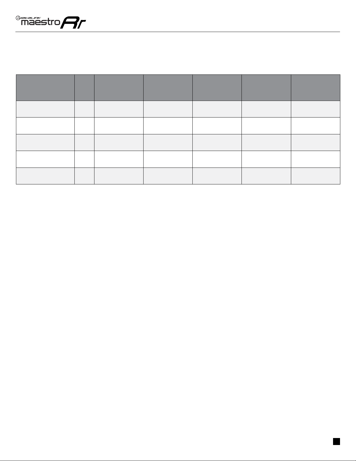
TROUBLESHOOTING TABLE
PROBLEM SOLUTION
When a button on the steering wheel is pressed, the light on the Maestro
module blinks but the radio does not respond.
Ensure the blue 4-pin steering wheel control cable is connected between the
maestro and the radio (the radio will use either the 3.5mm jack or the Blue/
Yellow wire, not both).
Refer to radio’s owners manual to verifie if the radio has this function:
Steering Wheel Control (ON/OFF) : choose ON.
or
Steering Wheel Control (Custom/Preset): choose Preset
The light on the Maestro is flashing RED ONCE. There is no firmware on the module; flash the RR module.
MAESTRO RR RESET PROCEDURE:
Turn the key to the OFF position, then disconnect all connectors from the module.
Press and hold the module’s programming button and connect all the connectors back to the module. Wait, the module’s LED will flash RED rapidly (this may
take up to 10 seconds).
Release the programming button. Wait, the LED will turn solid GREEN for 2 seconds to show the reset was successful.
TECHNICAL ASSISTANCE
Phone: 1-866-427-2999
Email: maestr[email protected]
Web: maestro.idatalink.com/support add www.12voltdata.com/forum/
IMPORTANT: To ensure proper operation, the aftermarket radio needs to have the latest firmware from the manufacturer. Please visit the radio
manufacturer’s website and look for any updates pertaining to your radio.
Other manuals for maestro Rr
48
Table of contents
Other iDataLink Adapter manuals