XX-XX PAGE X-XCLASSIC PAGE 1-1
LED STATUS
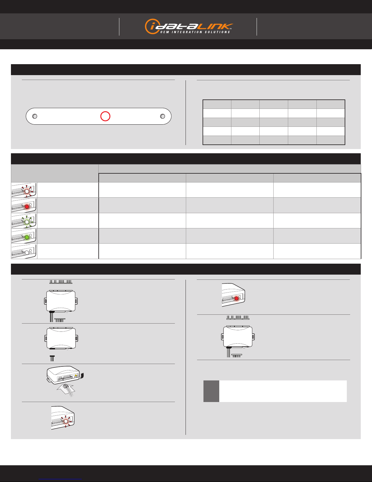
DIAGNOSTICS
DURING PROGRAMMING DURING REMOTE START WITH IGNITION OFF
Flashing RED Missing/wrong information from
fi rmware or vehicle Incorrectly programmed Incorrectly programmed or connected
Solid RED Waiting for more vehicle information Incorrectly programmed Not programmed waiting for more
vehicle information
Flashing GREEN Additional steps required to complete
programming
Correctly programmed and
operational
False ground when running status
from remote starter
Solid GREEN then OFF Correctly programmed Reset in progress Reset in progress
OFF No activity or already programmed Invalid ground when running status
from remote starter
At rest and ready for a remote start
sequence
MODULE DIAGNOSTICS
FACTORY RESET PROCEDURE
7Repeat programming procedure.
!Failure to follow procedure may result with a DTC or a
CHECK ENGINE error message.
1DISCONNECT all connectors
from module EXCEPT the black
4-PIN standard or optional data
connector.
6RECONNECT all connectors.
2DISCONNECT black 4-PIN
standard or optional data
connector.
4When LED fl ashes red,
RELEASE programming button.
5LED will turn solid red for 2
seconds.
RESET COMPLETED.
3PRESS AND HOLD programming
button while connecting either
4-PIN standard or optional data
connector.
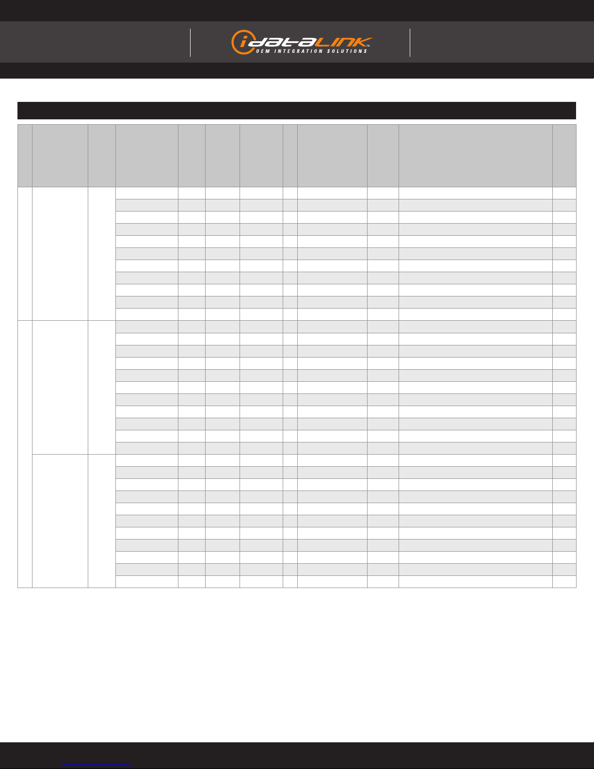
IDENTIFY VEHICLE YEAR
1Locate the Vehicle Identifi cation
Number (VIN) and identify the
10th character. 2Match the VIN’s 10th character
to its corresponding year.
L > 1990 S > 1995 Y > 2000 5 > 2005 A > 2010
M > 1991 T > 1996 1 > 2001 6 > 2006 B > 2011
N > 1992 V > 1997 2 > 2002 7 > 2007 C > 2012
P > 1993 W > 1998 3 > 2003 8 > 2008 D > 2013
R > 1994 X > 1999 4 > 2004 9 > 2009 E > 2014
4 Y 1 N53 A 5 T A L 8 D 5 R 0 X
Æ
This product is protected by one or more of the following patents: U.S. LETTERS PATENT NO. 5,719,551; 6,011,460; 6,243,004; 6,249,216; 6,275,147; 6,297,731; 6,346,876; 6,392,534; 6,529,124; 6,696,927; 6,756,885; 6,756,886; 6,771,167; 6,812,829; 6,924,750;
7,010,402; 7,031,826; 7,046,126; 7,061,137; 7,068,153; 7,015,830; 7,205,679; 7,224,083; 7,369,936; 7,378,945; 7,489,233; 7,501,937; CANADIAN PATENT NO. 2,320,248; 2,415,023; 2,426,670; 2,414,991; 2,415,011; 2,415,027; 2,415,038; 2,415,041; 2,502,893; 2,451,490;
2,452,296; 2,451,487; EUROPEAN PATENT NO. 1,053,128; DE 69807-941T2; U.S. 20020145535; 20060129282; 20060129284; 20040017284; 20080030316; 20090079552; EP1500565; 1538038; 1538037;
Page 9 of 9 ADS-AL(DL)-TL7-EN 20141104
INSTALL GUIDE
Guides Français disponibles au www.idatalink.com
WWW.IDATALINK.COM/SUPPORT Automotive Data Solutions Inc. © 2014
ALL IN ONE
Lexus/ToyoTa
Doc. No.: ##17111##