Ideal AKE GASTRO A Series Operating instructions

Symbolic photo
REPAIR MANUAL
Refrigeration Unit –electrics
Ausseer Kälte- und Edelstahltechnik GmbH
Document:
RM-Refrigeration Unit - electrics_EN
Application
date:
2021-08
Document no.
TD-AKE-00000339
Version:
21B
Comment:
Translated version of original document
Language:
English
Copyright 2021 AKE Ausseer Kälte- und Edelstahltechnik GmbH.
The contents of this publication may not be reproduced in whole or in part in any form or given to third
parties without the prior written consent of AKE GmbH. AKE GmbH reserves the right to make technical
changes as well as changes to this manual without prior notice.
All rights reserved.

REPAIR MANUAL
REFRIGERATION UNIT –ELECTRICS
Rev. 21B RM-Refrigeration Unit - electrics_EN page 2 of 25
This manual contains the repair manual for the built-in electrical components that are installed in the
following products/models:
Air Tower
EBS SB
Papilio
Vario presenter
AKV
Euro
Praline
Vitrine Switch GS
AZ
Flantastic
Salatbar Duo
Vitrine WK / Switch WK
BAK G-xx
Gastro A-xx
Salatbar Duo Switch
WHV
BAK KSL G-xx
Gastro EC
Salatbar Single
UKW SB
BAK L G-xx
Gastro G-xx
Salatbar Single Switch
BAK L G-xx
Gastro G-xx KL
Snack
Bakery
Gastro HCG-xx
SnackLine Cool
Bakery H-xx
Gastro HCOE-xx
Snacky Bistro
Bakery Kombi
Gastro O-xx
Snacky Cool
Bakery S
Green A-xx
Snacky WK
Brillant KR
Green FSV
Sushi Tower
Cake Tower
Green G-xx
Sushi-In
Caleo
Green KSL G-xx
Switch Flaps
Classic
Green L G-xx
Take Away Basic
Cold Flaps
Green O-xx
Take Away Cool
Convenience Tower
Hot Flaps
Tropical Flaps
Cool Bottle
KGU G-xx
Tropical Switch Flaps
Crush
KGW G-xx
UKW
Delicious Sushi
KP
UKW Switch / W-WK
EBS
cooling tower
Vario Food Counter
Note: “xx” = different height/width of the model

REPAIR MANUAL
REFRIGERATION UNIT –ELECTRICS
Rev. 21B RM-Refrigeration Unit - electrics_EN page 3 of 25
Table of contents
1General Information on this Repair Manual ..................................................................................... 4
1.1 Release notes.......................................................................................................................... 4
1.2 Information about the manufacturer ........................................................................................ 4
1.3 Contact information manufacturer/service............................................................................... 4
2Information about this Repair Manual.............................................................................................. 5
2.1 Safety information.................................................................................................................... 5
2.1.1 Special safety instructions for refrigerants .......................................................................... 6
2.2 Repair equipment / test equipment / material.......................................................................... 6
2.2.1 Tool...................................................................................................................................... 6
2.2.2 Material................................................................................................................................ 6
2.3 Disposal information................................................................................................................ 7
2.4 Information on custom designs................................................................................................ 7
3Repair of electrical components....................................................................................................... 8
3.1 Disconnect from the mains...................................................................................................... 8
3.2 Overview of components......................................................................................................... 8
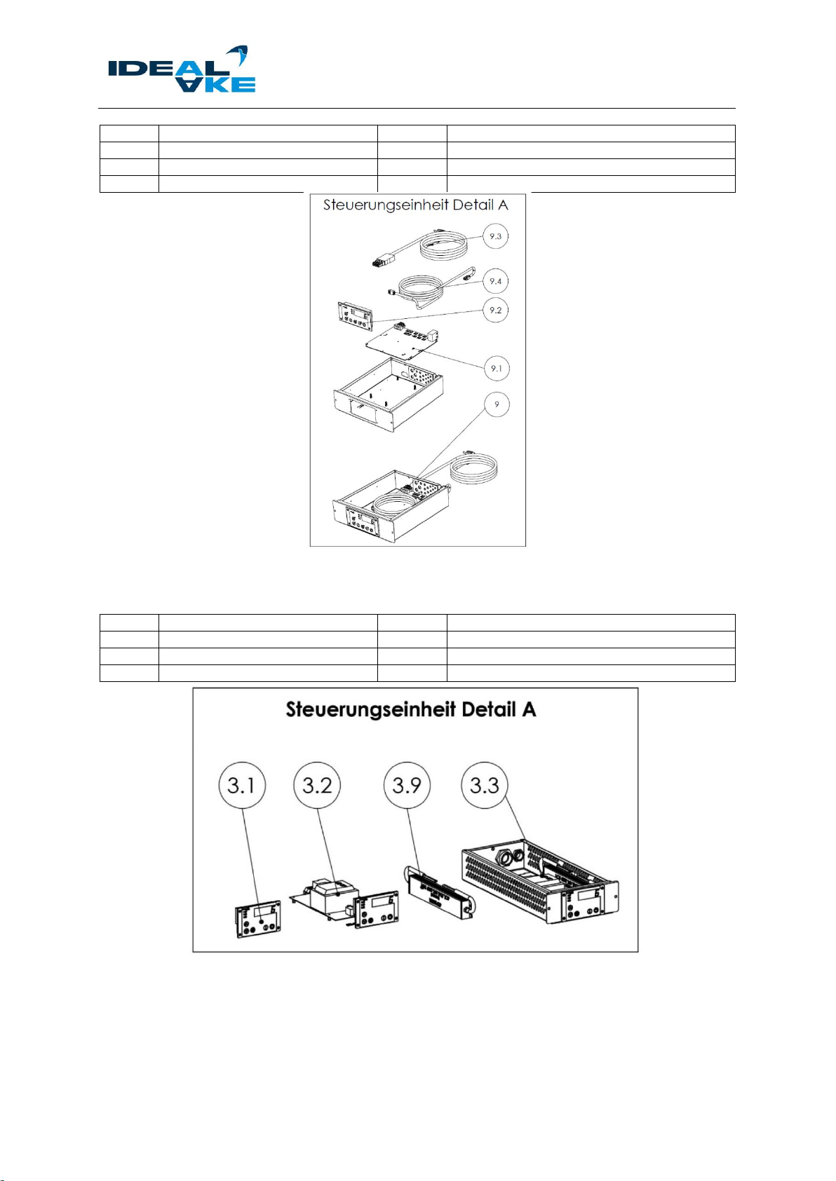
3.2.1 Parts of control unit ST200F................................................................................................ 8
3.2.2 Parts of control unit ST501.................................................................................................. 9
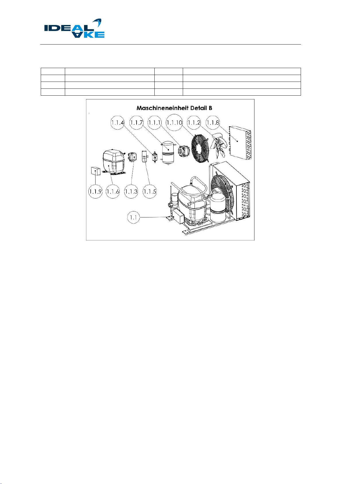
3.2.3 Condensing unit parts........................................................................................................ 10
3.3 Repair of the control unit ....................................................................................................... 11
3.3.1 Replacement of controller display ..................................................................................... 12
3.3.2 Replacement of controller board ....................................................................................... 12
3.4 Repair of the parts on the condensing unit............................................................................ 13
3.4.1 Fan motor repair................................................................................................................ 15
3.4.1.1 Replace fan blade...................................................................................................... 15
3.4.1.2 Replace fan motor ..................................................................................................... 16
3.5 Repair of the fan on the evaporator unit................................................................................ 17
3.5.1 Evaporator fan................................................................................................................... 18
3.6 Repair of temperature sensor / sensors................................................................................ 19
3.6.1 Repair of the sensors on the evaporator unit .................................................................... 19
3.6.1.1 Evaporator sensor ..................................................................................................... 19
3.6.1.2 Return air sensor on the evaporator.......................................................................... 20
3.6.1.3 Room sensor (supply air) in the air duct (special design) ......................................... 20
3.7 Repair of lighting unit............................................................................................................. 21
3.7.1 Repair of LED light strips................................................................................................... 21
3.7.2 Repair of LED transformer................................................................................................. 22
3.8Repair of frame heater........................................................................................................... 23
3.8.1.1 Frame heater "copper pipe"....................................................................................... 24
3.8.1.2 Frame heater “stuck on” ............................................................................................ 24
4Cleaning and Final Inspection........................................................................................................ 25

REPAIR MANUAL
REFRIGERATION UNIT –ELECTRICS
Rev. 21B RM-Refrigeration Unit - electrics_EN page 4 of 25
1 General Information on this Repair Manual
The repair manual presented here is intended for trained, authorised, qualified specialists who have the
necessary competence as well as expertise to perform any repair on products of AKE Ausseer Kälte-
und Edelstahltechnik GmbH.
Furthermore, this manual applies to all units of the cooling appliance and refrigerated display case type,
regardless of the different possible configurations regarding freestanding and Gastronorm dimensions.
The symbols used in this manual show the majority of configurations. Due to custom designs, many
other configurations of the cooling appliances and refrigerated display cases are still possible.
This document is an extension to the original documentation.
No part of this publication may be reproduced, stored, or in any way sent and published in any form.
1.1 Release notes
Version
Created:
Comments:
21A
01/2021
First version of the original description in German
21B
08/2021
Change of document name (refrigerated display cases -> refrigeration
unit); UKW SB model added
1.2 Information about the manufacturer
Ausseer Kälte- und Edelstahltechnik GmbH
Pichl 66
8994 Bad Mitterndorf, Austria
Telephone: +43 3624 21100 –0
Fax: +43 3624 21100 –33
E-mail: [email protected]
Web: www.ake-ideal.at
1.3 Contact information manufacturer/service
If you have any further questions about repair, service or maintenance, please contact the manufacturer
or your responsible service partner:
Technical Support (phone)
+43 3624 21100 –0
Technical Support (e-mail)
Orders / spare parts (e-mail)
Webshop / spare parts (online catalogue)
https://shop.ideal-ake.at/ersatzteilshop/
Availability of the spare parts
8 years after the last piece of the model group
has been put on the market
Minimum warranty period
See contract agreement / General Terms and
Conditions of AKE GmbH
Information about the model (Eprel)
https://ec.europa.eu

REPAIR MANUAL
REFRIGERATION UNIT –ELECTRICS
Rev. 21B RM-Refrigeration Unit - electrics_EN page 5 of 25
2 Information about this Repair Manual
It is important to read and understand the related operating manual including the corrections before
doing any repair work. The latter must be ensured by the operator. Any safety instructions given in the
operating manual are fully valid in this manual.
The following signal words and symbols are used in this document.
Imminent danger to the life of persons
Safety information with the DANGER signal word indicates imminent danger to the life and
health of persons. Failure to observe these safety instructions can lead to death or serious
damage.
Danger of personal injury (serious injuries) and possibly property damage as well
Safety information with the WARNING signal word indicates a dangerous situation that can
have an impact on the health of persons.
Failure to observe these safety instructions can lead to serious injuries.
This symbol with the comment INFORMATION refers to supporting information and
possible property damage.
2.1 Safety information
Personal protective equipment must be used for any work that is carried out.
More information can be found in the related operating manual in Chapter 1.14.
For the repair/assembly, observe the following in steps/activities:
Danger of crushing as well as danger from falling objects when
handling/aligning/positioning heavy individual components
When handling heavy objects, be aware of possible crushing dangers, also for other persons.
If possible, use both hands when you handle heavy objects. Get another person to help you
if necessary. When handling/aligning/positioning heavy individual components, protective
gloves and safety shoes must be worn.
Danger of being hit by the heating or cooling appliance during repair, cleaning and
maintenance work
Be aware of possible dangers of being hit by the unit.

REPAIR MANUAL
REFRIGERATION UNIT –ELECTRICS
Rev. 21B RM-Refrigeration Unit - electrics_EN page 6 of 25
2.1.1 Special safety instructions for refrigerants
Applies to all commercially available CFC/FC refrigerants, CO2and cold brine, propane/isobutane.
The rating plate indicates the refrigerant used in the device.
AKE refers to all safety datasheets and safety instructions provided by the refrigerant
manufacturer and their regulations for safe handling of the refrigerant.
All safety instructions in the related operating manual for handling refrigerant (Chapter 1.8
/ Chapter 1.9) must be observed and understood.
2.2 Repair equipment / test equipment / material
2.2.1 Tool
➢Screwdriver set (slotted/cross/TORX version)
➢Allen key set
➢Spanner set / socket wrench set
➢Cordless screwdriver
➢Metal drill set
➢Multimeter (depending on the unit configuration)
➢Cable cutting tool (side cutters, etc.)
➢Insulation stripper
➢Diagnostic device
2.2.2 Material
➢Cable ties
➢Adhesive tape / thermal tape
Only use original spare parts. Contact your service partner for more information. See
also see chapter 1.5 of the operating manual for the respective unit.
Special tools may be required in some circumstances, depending on the work/repair
effort. Contact the manufacturer or your service partner regarding this.

REPAIR MANUAL
REFRIGERATION UNIT –ELECTRICS
Rev. 21B RM-Refrigeration Unit - electrics_EN page 7 of 25
2.3 Disposal information
Various dangers when disposing of refrigerants
Wear protective gloves and safety glasses during the disposal of refrigerants (propane,
R404A, R134A etc.). Working with open flames is forbidden during the disposal of refrigerant.
Dispose of the refrigerant properly and in an environmentally compatible way.
Various dangers during the disposal of damaged parts/components.
When disposing of damaged parts/components wear protective gloves. Dispose of damaged
parts/components properly and in an environmentally compatible way.
Please observe the country-specific disposal guidelines.
Please note that some of the components of the unit are electronic parts. Therefore,
disposal using public waste management companies is not possible. Check your
obligations in accordance with the national WEEE provisions. Sorted disposal is
mandatory in any case.
Additional disposal information can be found in the respective operating manual of the appliance.
2.4 Information on custom designs
Custom designs are produced at the customer's request and may deviate from these repair instructions
due to a different assembly sequence / assembly steps, etc.
The position of the installed components may differ from the standard units and may not be graphically
represented correctly in these repair instructions.
If there is a significant deviation for special designs, the respective components / repair steps will be
described and documented in separate supplements to this repair manual.
However, the repair procedures described for standard components are identical, and are consequently
fully valid and must be followed by the repair personnel.
Depending on the model/unit or customer-specific installations, further disassembly
steps may be necessary. Contact your service partner or manufacturer regarding this.

REPAIR MANUAL
REFRIGERATION UNIT –ELECTRICS
Rev. 21B RM-Refrigeration Unit - electrics_EN page 8 of 25
3 Repair of electrical components
All accident prevention regulations (in the country-specific version) must be observed before any work
is carried out on the unit!
3.1 Disconnect from the mains
Switch the unit off. Disconnect all poles of the unit from the mains, or remove the mains plug from the
mains socket properly.
Danger from electrical voltage on live components
The power supply must be disconnected before all cleaning and service work. To do this,
unplug the unit or disconnect all poles from the power mains.
3.2 Overview of components
All electrical components that are installed in standard units are listed (example using "UKW"):
No.
Description/article
A
Control unit
3.4
Evaporator fan
3.6; 3.7
Temperature sensor
B
Condenser set
Exploded view (UKW)
Exploded view (controller)
Depending on the model/unit or customer-specific installations, additional components
may be built in. Contact your service partner or manufacturer regarding this.
3.2.1 Parts of control unit ST200F
Overview of all spare parts of the control unit.

REPAIR MANUAL
REFRIGERATION UNIT –ELECTRICS
Rev. 21B RM-Refrigeration Unit - electrics_EN page 9 of 25
No.
Description/article
No.
Description/article
9
Complete control unit
9.3
Connecting cable, 3m, power cord
9.1
Controller board ST200F
9.4
ZB cable connection RJ45
9.2
Display ST521
X
LED transformer (not shown)
Exploded view of control unit (ST200F)
3.2.2 Parts of control unit ST501
Overview of all spare parts of the control unit ST501
No.
Description/article
No.
Description/article
3.1
Display ST521
3.9
LED transformer
3.2
Control unit ST501
x
Connecting cable, 3m, power cord
3.3
Complete control unit
x
ZB cable connection RJ45
Exploded view of control unit (ST501F)

REPAIR MANUAL
REFRIGERATION UNIT –ELECTRICS
Rev. 21B RM-Refrigeration Unit - electrics_EN page 10 of 25
3.2.3 Condensing unit parts
Overview of all spare parts of the condensing unit:
No.
Description/article
No.
Description/article
1.1.1
Fan motor
1.1.6
Compressor
1.1.2
Condenser fan
1.1.5
Capacitor
1.1.3
Power distributor for motor
1.1.9
Terminal box
Graphical representation (condensing unit)

REPAIR MANUAL
REFRIGERATION UNIT –ELECTRICS
Rev. 21B RM-Refrigeration Unit - electrics_EN page 11 of 25
3.3 Repair of the control unit
Unplug the power cord from the connection of the controller housing.
Release the unlocking clip of the connector.
Remove the locating screws of the controller housing, and pull the entire control unit out of the holder.
Pull the entire unit out of the holder only far enough to access the wiring of the control unit.

REPAIR MANUAL
REFRIGERATION UNIT –ELECTRICS
Rev. 21B RM-Refrigeration Unit - electrics_EN page 12 of 25
3.3.1 Replacement of controller display
Depending on the model/unit, a different controller display is installed in the housing. If anything is
unclear, please contact your service partner.
Remove the connecting cable (control line) from the display connection. Remove the locating screws
of the display and remove it from the housing. Depending on the model, it may not be necessary to
remove the controller housing to replace the display.
Control unit Störk ST200F
Control unit Störk ST501
Controller housing, complete
Störk “ST501” display
Störk “ST521” display
Put the new original replacement display back into the housing, secure it with the locating screws, and
connect it to the control line.
3.3.2 Replacement of controller board
Depending on the model/unit, a different controller board is installed in the housing.
Remove all cables / control lines (control line) from the circuit board, remove the fasteners (screws /
mounting clips) and take them out of the housing.
Controller board (marked in red)
Circuit board fastening
Put the new original replacement board back into the housing, secure it and connect all cables / control
lines.
All cables / control lines must be correctly reconnected according to the valid product-
specific circuit diagram!

REPAIR MANUAL
REFRIGERATION UNIT –ELECTRICS
Rev. 21B RM-Refrigeration Unit - electrics_EN page 13 of 25
3.4 Repair of the parts on the condensing unit
Depending on the model, the condensing unit is installed as a unit or with individual components, and
the accessibility differs from the variant shown.
Remove the retaining plate (securing) of the condensing unit, and pull the entire unit out of the lower
tray support.
Symbolic photo
Make sure that the unit is not pulled completely out of the suspension. Damage to the
condensing unit may occur if it is dropped.
Lift the condensing unit onto a suitable support.
Risk of crushing when the condensing unit is lifted out
When handling heavy objects, be aware of possible crushing dangers. Get another person to
help you if necessary.
When lifting out the condensing unit, be careful not to damage any cables, evaporator fins
or pipes.
Depending on the product/model, the condensing unit may be installed differently on the
unit.

REPAIR MANUAL
REFRIGERATION UNIT –ELECTRICS
Rev. 21B RM-Refrigeration Unit - electrics_EN page 14 of 25
Overview of all parts of the condensing unit:
No.
Description/article
No.
Description/article
1.1.1
Fan motor
1.1.6
Compressor
1.1.2
Condenser fan
1.1.7
Refrigerant collector
1.1.3
Power distributor for motor
1.1.8
Condenser
1.1.4
Dryer
1.1.9
Terminal box
1.1.5
Capacitor
1.1.10
Protective grating, fan
Exploded view (condensing unit)
Depending on the unit configuration, this kit might have to be replaced as a complete
unit.
Disconnect all electrical connections in the terminal box as well as the earth lead.
Terminal box (distribution box)
Connector terminal box
Earth lead

REPAIR MANUAL
REFRIGERATION UNIT –ELECTRICS
Rev. 21B RM-Refrigeration Unit - electrics_EN page 15 of 25
3.4.1 Fan motor repair
3.4.1.1 Replace fan blade
To replace the condenser fan, all the steps from Chapter 3.4 must be completed first.
Remove all screws from the fan grille, and lift the entire fan from the condenser.
Remove all screws from the fan blade and detach it from the motor mount.
Put the new fan back on the motor mount and secure it with the screws.
Use a thread locker (Loctite)!

REPAIR MANUAL
REFRIGERATION UNIT –ELECTRICS
Rev. 21B RM-Refrigeration Unit - electrics_EN page 16 of 25
3.4.1.2 Replace fan motor
To replace the fan motor of the condenser, all the steps from Chapter 3.4.1.1 must be completed first.
Remove all screws and pull the fan motor out of the ventilation grille as shown.
Remove the necessary cables of the fan motor from the terminal box.
Terminal box (distribution box)
Terminal box wiring
Place the new fan motor in the correct installation position in the mount of the ventilation grille, and
fasten it with the related screws.
Install the fan blade as described in Chapter 3.4.1.1.
Note: Use a thread locker (Loctite)!
Wire the new fan motor correctly in the terminal box of the condensing unit according to the valid product-
specific wiring diagram.

REPAIR MANUAL
REFRIGERATION UNIT –ELECTRICS
Rev. 21B RM-Refrigeration Unit - electrics_EN page 17 of 25
3.5 Repair of the fan on the evaporator unit
Depending on the model, it may be necessary to disassemble components to reach the evaporator unit.
The described work steps may differ from your unit.
Disassemble/remove all shelves, extendible drawers, etc. to access the evaporator unit.
Fold up the protective plate (evaporator cover).
Remove the locating screws.
Close the protective plate (evaporator cover). Lift the fan housing upwards out of the anchors.
ATTENTION: The sensor cables are connected to the fan housing. Carefully remove the sensor
from the evaporator.

REPAIR MANUAL
REFRIGERATION UNIT –ELECTRICS
Rev. 21B RM-Refrigeration Unit - electrics_EN page 18 of 25
3.5.1 Evaporator fan
Remove the connection cables of the respective defective fan from the connection terminal on the inside
of the fan housing, remove the locating screws and dismantle the associated fan guard grille.
Symbolic photo
Inside of fan housing
Fan guard grille
Remove the defective fan from the inside of the fan housing.
Place the new fan of the same design back into the mount. Fasten it with the locating screws including
the fan guard grille.
Install or secure the power supply cable of the fan with cable ties at suitable positions.

REPAIR MANUAL
REFRIGERATION UNIT –ELECTRICS
Rev. 21B RM-Refrigeration Unit - electrics_EN page 19 of 25
3.6 Repair of temperature sensor / sensors
3.6.1 Repair of the sensors on the evaporator unit
The temperature sensors are mounted on the evaporator unit in standard models. This may differ from
standard units for custom designs. Please contact your service partner or the manufacturer regarding
this.
3.6.1.1 Evaporator sensor
Remove the sensor from the evaporator. If necessary, remove all cable ties from the cable harness.
Remove the wiring from the control unit (circuit board), and pull the entire control cable out of the tubing.
Remove the sensor from the support plate (plastic plate).
Symbolic photo
Danger from electrical voltage on live components
The power supply must be disconnected before all conversion work. To do this, unplug the
unit or disconnect all poles from the power mains.
Insert a new original spare part, install the cable with suitable fastening materials (cable ties) and
connect it according to the valid product-specific wiring diagram.
Connect the new sensor to the support plate, and place it in the correct position on the evaporator.

REPAIR MANUAL
REFRIGERATION UNIT –ELECTRICS
Rev. 21B RM-Refrigeration Unit - electrics_EN page 20 of 25
3.6.1.2 Return air sensor on the evaporator
Remove the sensor from the holder on the fan housing. If necessary, remove all cable ties / fastening
materials from the cable harness.
Symbolic photos
Remove the wiring from the control unit (circuit board), and pull the entire control cable out of the tubing.
Symbolic photo
Insert a new original spare part, install the cable with suitable fastening materials (cable ties) and
connect it according to the valid product-specific wiring diagram.
3.6.1.3 Room sensor (supply air) in the air duct (special design)
Depending on the model, an additional temperature sensor may be fitted.
Remove all shelf supports and covers from the rear wall of the unit to gain access to the temperature
sensor and cable routing.
Remove the sensor from the holder. If necessary, remove all cable ties / fastening materials from the
cable harness.
Insert a new original spare part, install the cable with suitable fastening materials (cable ties) and
connect it according to the valid product-specific wiring diagram.
This manual suits for next models
46
Table of contents