Ideal Boilers 4.5 User manual

installation
Ideal airtherm
air source heat pump
Your Ideal installation guide
4.5, 9, 12
When replacing any part on this heat pump, use only spare parts that you can be
assured conform to the safety and performance specification that we require. Do not
use reconditioned or copy parts that have not been clearly authorised by Ideal Boilers.
For the very latest copy of literature for specification purposes please visit our website
www.idealboilers.com where you will be able to download the relevant information in pdf format.
For users guide see reverse of book
June 2009 UIN 204855 A02
535752 Issue 2

2Ideal airtherm - Air Source Heat Pump - Installation

3Ideal airtherm - Air Source Heat Pump - Installation
Ideal airtherm 4.5, 9 & 12
Air Source Heat Pump
Destination Country: GB, IE
CONTENTS
How the Heat Pump Works .......................................... 4
Introduction ................................................................... 5
Heating with a heat pump ............................................. 5
Safety precautions ....................................................... 5
Location ......................................................................... 6
Unpacking ...................................................................... 6
Plumbing - pipework ..................................................... 7
Plumbing - buffer tank and hot water cylinder ........... 7
Electrical ........................................................................ 8
Electrical Connections ................................................. 8
Internal wiring ............................................................... 8
Electrical Diagrams ................................................ 9, 10
Internal Machine Circuit Diagrams ...................... 11, 12
Frost protection ........................................................... 13
Control Panel ............................................................... 13
Commissioning ........................................................... 14
Handing Over ............................................................... 14
Fault finding ................................................................. 15
Data sheet ................................................................... 16
Machine dimensions, access panels and
electrical/water connections .......................... 17,18,19
System designs - S Plan ...................................... 20, 21
System designs - W Plan ..................................... 22, 23
System designs - Bivalent installation ...................... 24
Refrigeration Diagrams ........................................ 25, 26
Optional weather compensation ................................. 27
Mounting the sensor ................................................... 28
Wiring of the Optional Weather Compensator ......... 28
Commissioning Checklist .......................................... 29

4Ideal airtherm - Air Source Heat Pump - Installation
DOMESTIC
PREMISES
OUTSIDE
AIR
The EVAPORATOR collects heat from the
outside ambient air, pre-heated by the sun.
With Ideal, heat pumps high volumes of
outside air are drawn into the unit by the fan
and expelled through the evaporator fins.
The evaporator has liquid refrigerant
passing through it, which is at a
considerably lower temperature than the
ambient air, therefore the air gives up its
heat to the refrigerant, which then vaporizes.
This pre-heated vapour now travels to-
The COMPRESSOR where it is
compressed and upgraded to a
much higher temperature. The hot
vapour now enters-
The EXPANSION DEVICE and from
there, now at low pressure, it is
returned to the evaporator and the
cycle starts again.
The CONDENSER where it is surrounded
by water from the heating system. The heat
is given up to the cooler water and the now
cooler refrigerant returns to its former liquid
state but still under high pressure from the
compressor. This pressure is released by
passing the liquid through -
Coefficient of Performance
The efficiency of a Heat Pump is usually called its 'Coefficient of Performance' - (C.O.P.) which is simply a ratio of
heat output to energy input, both being expressed in kW. Thus a Heat Pump absorbing 1 kW of electricity, collecting
4 kW of energy from the air, and delivering 5 kW of heat to the pool water is said to have a C.O.P. of 5:1.
Naturally this ratio will vary according to the temperature of the water and the ambient air.
HOW THE HEAT PUMP WORKS
The Ideal airtherm Heat Pump provides thermodynamic heating by means of a vapour compression cycle
(similar to that employed in a conventional refrigerator), in addition to operating as an active solar collector.

5Ideal airtherm - Air Source Heat Pump - Installation
GENERAL
INTRODUCTION
This installation manual is accompanied by a user guide (see
reverse of this book), a commissioning record sheet and a
warranty registration card, all of which should be left with the
householder. The user guide explains how the system works,
how it is controlled and what to do in the event of a problem.
The commissioning record sheet must be completed as its
production will be required in the event of a warranty claim.
HEATING WITH A HEAT PUMP
The Ideal heat pump is designed to operate up to 65oC water
temperature for the domestic hot water delivery, and negates
the need for direct electrical heating in the form of an electrical
emersion heater. The unit also provides space heating
temperatures variable from 35oC to 55oC.
Heat pumps for domestic heating are a fully proven technology
which will give many years of trouble-free service. Ideal Heat
Pumps which are MCS approved have been specifically
designed for optimum operation in the UK’s climate.
However, unlike an oil or gas boiler which may be oversized for
the heating demand of the property and therefore regularly
cycles on and off, a heat pump is closely matched to the heat
demand and is designed to run for long periods without
switching on/off.
The following steps must therefore always be taken to ensure
a successful installation. Major problems can occur if they are
not taken and failure to comply will invalidate the warranty.
a. SAP or equivalent heat loss calculations must be
established with the results recorded on the
commissioning sheet.
b. The heat pump must be correctly sized in relation to the
calculated heat losses.
c. The space heating system must be capable of satisfying
the heat demand at the water flow temperature set for the
heat pump. This is particularly important where retro-fitting
a heat pump to a radiator system designed originally for a
Delta T of 60oC, as the heat pump will run at a Delta T of
30oC. In this situation, you will normally need to fit larger
radiators.
d. The electrical supply must be adequate to meet the start
current demand.
e. The heat pump and the associated heating system must be
commissioned in accordance with the procedures laid
down in this manual.
A heat pump may be fitted on a stand-alone basis (monovalent
system) to satisfy the full heating and hot water demand of the
property or in parallel with an existing boiler (bivalent system).
In the case of a bivalent installation the heat pump is sized to
provide a variable proportion of the annual heating requirement
(say 85%) with the existing boiler integrated to deliver the
balance on the coldest days. In bivalent systems, the heat
pump is sometimes only linked to the space heating system
which eliminates the requirement to fit a new DHW cylinder.
Standard designs for several different configurations, including
plumbing and electrical circuits, are included in this manual.
REGULATIONS
The Ideal airtherm models confirm
• BS EN60335-1:2002 &2-40:2003, and therefore comply with
the Low Voltage Electrical Equipment Directive 73/23/
EEC;93/68/EC.
• BS EN ISO 12100-1:2003, BS EN ISO 12100-2:2003, BS
EN ISO13857:2008: BS EN ISO 13850:2006, and therefore
comply with the Supply of Machinery (Safety) Directive 98/
37/EC.
• BS EN55014-1:2000+A1:2001+ A2:2002, 14-
2:1997+A1:2001, EN61000-3-2:2000, -3-3:1995 + A1:2001,
-4-2:1995, -4-3:1996, -4-4:1995, -4-5:1995, -4-6:1996, -4-
11:1995.
and therefore comply with the Electromagnetic
Compatibility Directive 2004/108/EC.
• Comply with the Pressure Equipment Directive 97/23/EC,
Fluid Group 2,Category 1.
• Compliant to RoHS Directive 2002/95/EC
SAFETY PRECAUTIONS
a. The unit must be securely installed on a structure that can
sustain its weight. If mounted on an unstable structure, it
may fall causing injury or damage.
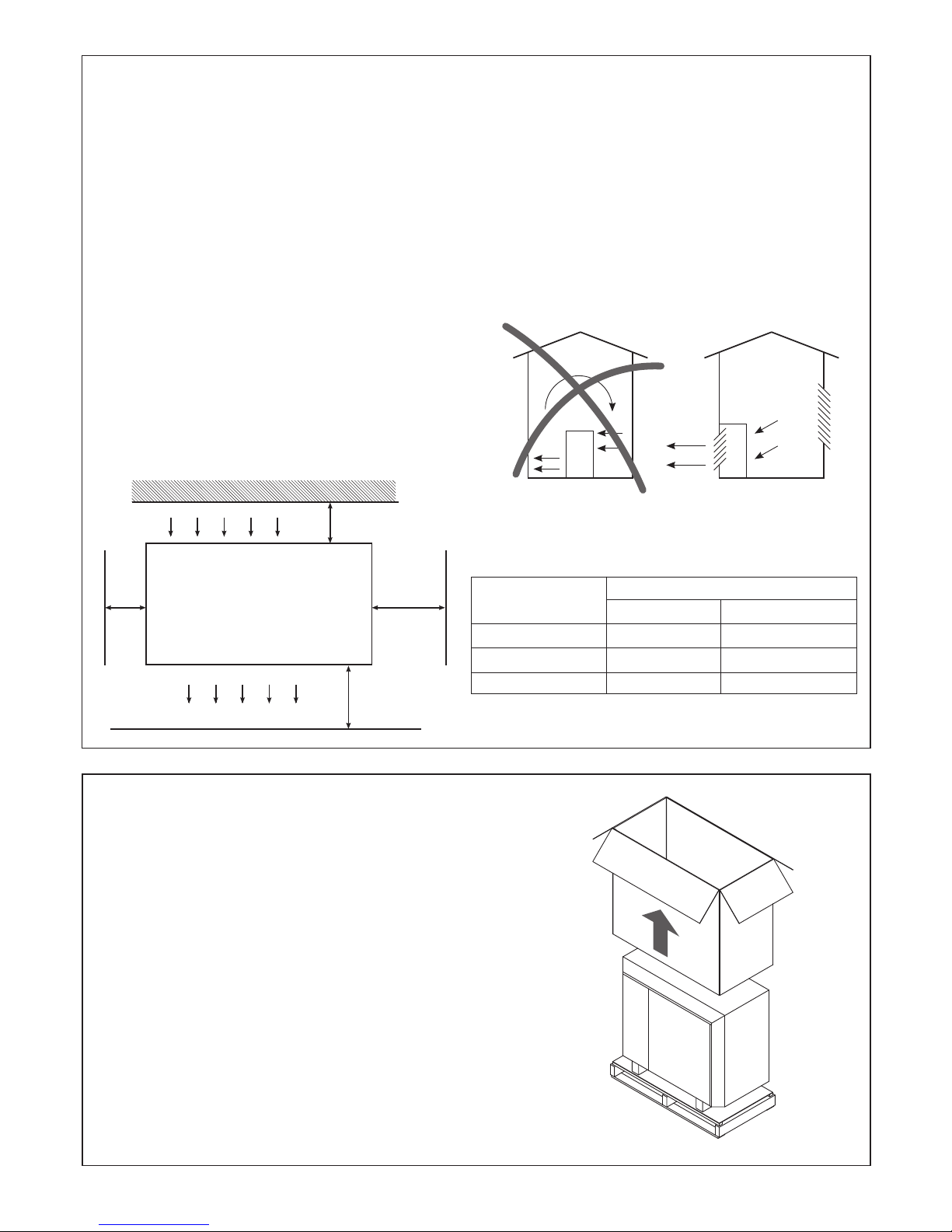
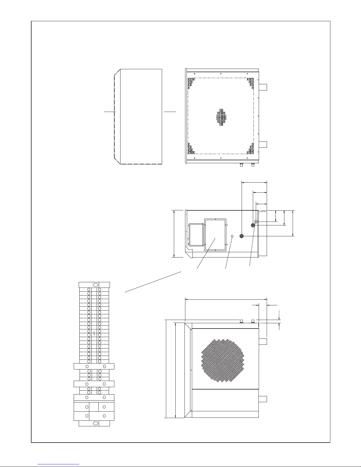
b. If the heat pump is installed in an enclosed area, sufficient
ventilation must be provided so as not to impede the air flow
through the unit and to prevent the concentration of
refrigerant gas in the room building up in the event of a leak.
(See diagram - page 6)
c. All electrical work must be performed by a qualified
technician and comply with the latest I.E.E (17th) Regulations.
The machine should be installed in accordance with EMC
2004/108/EC.
d. Electricity to the unit must be supplied through dedicated
power lines and the correct voltage and circuit breakers must
be used. Power lines with insufficient capacity or incorrect
electrical work may result in electric shock or fire. The
electrical ratings of Ideal heat pumps are included in the
datasheet on page 16 of this manual.

6
INSTALLATION
Ideal airtherm - Air Source Heat Pump - Installation
150mm
AIR INLET
AIR OUTLET
1500mm
500mm50mm
AT9630
TYPICAL INSIDE OR PLANT ROOM INSTALLATION
Grill or apertures MUST comply with Figures (See Table 1)
AIR FLOW
AIR FLOW
INCORRECT CORRECT
AT9631
Table 1
Model Minimum Free Area m2
Inlet Discharge
airtherm 4.5 0.440 0.114
airtherm 9 0.440 0.114
airtherm 12 0.619 0.1313
LOCATION
The heat pump is suitable for outside installation.
a. Select a location where any potential noise disturbance is
minimised.
b. Provide a firm level base capable of supporting the weight
of the machine. Fixing holes are provided for bolting the
machine down to the base.
c. If wall mounting, ensure that the wall and framework are
capable of supporting the machine and use anti-vibration
mounts to prevent noise transmission. The weights of the
heat pumps are included on the data sheet on page 16 of
this manual.
d. If installing in a location exposed to strong wind, do not
face the air outlet of the unit against the direction of the
wind as wind entering the unit may impede the normal
airflow and result in a malfunction.
e. Allow for the minimum clearances around the machine, as
shown below, required for unobstructed air flow and
access to service panels. A clearance of 1 metre above the
unit is recommended for servicing access through the top
panel.
f. Consider protection from extreme weather conditions with a
cover or enclosure if the machine is installed externally
g. Consider fitting a protective guard where the machine could
be exposed to vandalism or other damage.
h. If installed in a plant room or other building, ensure that the
air outlet is positioned directly adjacent to the outside wall
with inlet and discharge grilles or apertures of minimum free
areas as detailed below.
UNPACKING
AT9656
1. Position the heat pump close to point of installation on a
sound flat surface and in an area large enough to unpack
the unit.
2. Carefully remove the plastic strapping securing the unit
and carton sleeve to the pallet.
3. Fold back the top flaps to gain access to the literature
pack.
4. Remove the instructions and read thoroughly before
unpacking the product.
5. When ready for installation lift off the cardboard carton
sleeve.
6. Carefully remove the unit from the pallet.

7
INSTALLATION
Ideal airtherm - Air Source Heat Pump - Installation
PLUMBING - PIPEWORK
a. Ideal heat pumps have water flow and return connections
as follows:
· The airtherm 4.5 and 9 models have ¾” BSP parallel,
male threads
· The airtherm 12 has 1" BSP, parallel, male threads
b. Couplings suitable for disconnection should be installed
with isolating valves on the flow and return of the heat
pump to ease installation and maintenance. During the
initial installation, these should be the last connections
made so as to avoid any stresses on the unit connections.
c. A drain valve or plug should be fitted to the lower pipe to
facilitate drain down for servicing.
d. The condensate drain at the base of the unit collects the
condensation from the evaporator fins. This should be run
away to waste from the ¾” PVC pipe on the side of the heat
pump. The routing of the drain must be made to allow a
minimum fall of 1 in 20 away from the unit, throughout its
length.
e. Do not allow pipe work to run in front of service panels.
f. All pipe work must be adequately supported with
allowance for expansion/contraction and should be
insulated to avoid unnecessary heat loss.
a. The Ideal air source heat pump is normally designed to
operate with a buffer tank which prevents short cycling
during normal operation and provides a thermal store to
aid defrost of the heat pump. The size of the buffer tank
needed varies with the size of the ASHP unit as shown
below.
b. Where the ASHP is required to supply domestic hot water,
a special DHW cylinder (Ideal cylinder) should be
purchased with each air to water heat pump. These
cylinders have a larger primary coil compared to standard
cylinders and are supplied with a special tank thermostat.
An immersion heater is fitted for back-up DHW heating.
c. Where indirect pressurised cylinders are fitted, they should
be installed in compliance with the relevant Water
Regulations and Building Regulations.
HEAT PUMP BUFFER TANK CAPACITY
airtherm 4.5 50 litres
airtherm 9 95 litres
airtherm 12 150 litres
PLUMBING - BUFFER TANK AND HOT WATER CYLINDERS

8
INSTALLATION
Ideal airtherm - Air Source Heat Pump - Installation
a. A separately fused single phase supply is required. With
all power switched off, remove the electrics access panel
to gain access to the terminals in the electric box. The
supply cable, entering the unit through knock outs in the
panel, can then be fed through to connect into the live/
neutral/earth terminals.
b. An MCB type C or D fuse must be used. (Refer to data
sheet on page 16 of this manual).
c. A local isolator should be fitted within 2 feet of the unit to
comply with I.E.E. regulations. Power to the unit is
indicated by the red indicator light on the console (mains
lamp).
d. A separate fused spur is normally used to supply the
central heating programmer and controls.
e. There are 10 connections to be made between the Ideal
heat pump and the control wiring centre. A multi core cable
with sufficient capacity will need to be provided and
installed. In most cases a 12 core 0.5mm control cable is
used.
ELECTRICAL
ELECTRICAL CONNECTIONS
a. The electrical connections diagrams are on pages 9 and
10 of this manual.
b. The wiring junction box is located behind the access
panel below the unit’s control panel
c. For the heat pump to operate, you must have a live signal
into terminal 1 (space heating) or terminal 9 (DHW).
INTERNAL WIRING
a. Internal wiring diagrams are on pages 11 and 12 of this
manual.
b. External wiring will depend on the heating system design
and is covered in the system design section of this
manual.
f.The unit may be live even when the mains lamp is off due
to live feeds from the external control system. The
‘programmer live’ light on the control panel confirms the
presence of a supply.
g. The heat pump can operate in one of two modes, either
set as supplied, with the unit biased to hot water, or with
no bias for hot water or heating.
h. Ideal Boilers would always recommend a system with the
heating biased to hot water. However if room heating and
hot water heating are required at the same time, the link
between terminals 11 and 12 should then be fitted. There
is then no bias between room heating and hot water
heating.
Notes:-
i. Where the link is fitted the unit will deliver 65ºC flow
temperature during periods of DHW demand and this
must be considered at system design with
consideration to this temperature feeding radiators or
under floor heating at these times.
ii. The link cannot be fitted when the heat pump is
plumbed in to a ‘W Plan’ system.

9
INSTALLATION
Ideal airtherm - Air Source Heat Pump - Installation
ELECTRICAL CONNECTIONS IDEAL AIRTHERM 4.5 & 9
23 456 7 891011 12 13 14 15 16 17 18 19 20 21 22 24 29 30 32 331
LNE
CONTROL LIVE (OUT)-
(IDEAL TEST TERMINAL)
COMPRESSOR 'C'
COMPRESSOR 'R'
COMPRESSOR 'S'
DEFROST VALVE
DEFROST VALVE
FAN N
FAN L
MAINS IN L
MAINS IN N
MAINS IN E
LIVE GO SIGNAL FOR DHW (IN)
NEUTRAL
ROOM HEATING (OUT)
BYPASS ROOM HEATING (OUT)
NEUTRAL
LIVE GO SIGNAL FOR HEATING (IN)
LIVE GO SIGNAL FOR HEATING (OUT)
LIVE GO SIGNAL FOR DHW (OUT)
PROGRAMMER DHW PERIOD (IN)
BUFFER TANK HEATING DEMAND (IN)
LIVE GO SIGNAL FOR HEATING PUMP W AND Y PLAN ONLY (OUT)
HEATING VALVE Y PLAN (OUT)
PROGRAMMER SIGNAL (IN)
VOLT FREE TERMINALS
BUFFER TANK IMMERSION HEATER
LINK FOR SIMULTANEOUS
HEATING AND HOT WATER
VALVE 3
230/240V
ETH
ETH
ETH
AT9640
SEE SECTION 5
Live
Neutral
Earth
1
2
3
4
5
6
7
8
9
10
11
12
13
14
15
16-23
24
29
30
32
33
18
19
20
23
16
17
7
11
22
2
18
19
20
23
16
17
11
22
7
2
Defrost
Terminals
Add link if
required
Mains Power Supply
Live Go for Programmer for DHW
Neutral
Earth
Live Out Space Heating
Live Out Defrost
Neutral
Earth
Programmer Live Ideal Test Terminal
Live Go from Programmer for Space Heating
Live Out Space Heating Zone Valve
Link for Simultaneous Space Heating / DHW
Live Out DHW Zone Valve
Live in from Programmer for DHW Time Clock
Buffer Tank Stat / Ambient Stat Live in (DHW Only)
Internal Connections
Live Out Circulating Pump
Zone Heating Valve (Live out Y Plan Only)
Live in from Programmer (Programmer Live Lamp)
Volt Free Terminal
Buffer Tank Immersion Heater Control
Heat
Pump
Terminal
Connections
Connect to: Connect to:
S Plan Connections airtherm 4.5 & 9
External Wiring Connections
W Plan Connections airtherm 4.5 & 9
External Wiring Connections
Notes

10
INSTALLATION
Ideal airtherm - Air Source Heat Pump - Installation
ELECTRICAL CONNECTIONS IDEAL AIRTHERM 12
2NL45673 8 9 10 11 12 13 14 15 16 17 18 19 20 21 22 23 24 25 26 27 28 29 30 31 32 331
CONTROL LIVE (OUT)-
(IDEAL TEST TERMINAL)
COMPRESSOR 1 'C'
COMPRESSOR 1 'R'
COMPRESSOR 1 'S'
COMPRESSOR 2 'C'
COMPRESSOR 2 'R'
COMPRESSOR 2 'S'
REVERSING VALVE
REVERSING VALVE
DEFROST VALVE
DEFROST VALVE
FAN L
FAN N
LIQUID LINE SHUT OFF
MAINS IN L
MAINS IN N
MAINS IN E
LIVE GO SIGNAL FOR DHW (IN)
NEUTRAL
ROOM HEATING (OUT)
BYPASS ROOM HEATING (OUT)
LIVE GO SIGNAL FOR HEATING (OUT)
LIVE GO SIGNAL FOR HEATING (IN)
VALVE 1 LIVE GO SIGNAL FOR DHW (OUT)
PROGRAMMER WATER PERIOD (IN)
BUFFER TANK HEATING DEMAND (IN)
LIVE GO SIGNAL FOR HEATING PUMP W AND Y PLAN ONLY (OUT)
HEATING VALVE Y PLAN (OUT)
PROGRAMMER SIGNAL (IN)
VOLT FREE TERMINALS
BUFFER TANK IMMERSION HEATER
A1 15 Y1
LINK FOR SIMULTANEOUS
HEATING AND HOT WATER
VALVE 3
230/240v
ETH
E
ETH
ETH
AT9641
Live
Neutral
Earth
1
2
3
4
5
6
7
8
9
10
11
12
13
14
15
16-23
24
29
30
31
32
33
18
19
20
23
16
17
7
11
22
2
18
19
20
23
16
17
11
22
7
2
Defrost
Terminals
Add link if
required
Mains Power Supply
Live Go for Programmer for DHW
Neutral
Earth
Live Out Space Heating
Live Out Defrost
Neutral
Earth
Programmer Live Ideal Test Terminal
Live Go from Programmer for Space Heating
Live Out Space Heating Zone Valve
Link for Simultaneous Space Heating / DHW
Live Out DHW Zone Valve
Live in from Programmer for DHW Time Clock
Buffer Tank Stat / Ambient Stat Live in (DHW Only)
Internal Connections
Live Out Circulating Pump
Zone Heating Valve (Live out Y Plan Only)
Live in from Programmer (Programmer Live Lamp)
Internal Connection
Volt Free Terminal
Buffer Tank Immersion Heater Control
Heat
Pump
Terminal
Connections
Connect to: Connect to:
S Plan Connections airtherm 12
External Wiring Connections
W Plan Connections airtherm 12
External Wiring Connections
Notes
SEE SECTION 5

11
INSTALLATION
Ideal airtherm - Air Source Heat Pump - Installation
INTERNAL MACHINE CIRCUIT DIAGRAM - AIRTHERM 4.5 AND 9
L
6
4
COMPRESSOR 1
TB 11
TB 12
TB 10
TB 1
TB
2
TB
6
3
52
8
A2
A2A1
A1
R2
R2
R2
R5
R5
7
4
4
7
R2
L
N
A2
A1
R1
SMART
STARTER
COMPRESSOR 1
SMART STARTER
COMPRESSOR 1
LINK FOR SIMULTANEOUS
HOT WATER AND HEATING
RUN
CAP
ON
N
L1
R
NS
RC
(1) (2)
65 DEG STAT
BREAK ON
TEMP RISE
DIG STAT
DIG STAT
1STAGE
MAKE ON
FALL
OUT1
LIVE GO SIGNAL
FOR HOT WATER
NEUTRAL
C
H
HP
SWITCH
1
9
FAULT
LAMP
MAINS
LAMP
5A
FUSE
NEUTRAL
(RED)
(AMBER)
LIVE GO SIGNAL
FOR HEATING
DEFROST
VALVE
DEFROST LAMP
FAN
FAN CAP
(GREEN)
2019
21 22
PROBE
10 11
TB 4
TB 5
BYPASS ROOM
HEATING
ROOM
HEATING
N
TB 9
LIVE GO
SIGNAL
FROM ROOM STAT
FOR HEATING
R3
A1
A2
R7
A1
A2
R8
85
96
R7
85
R7
93
TB14
R8
A1
A2
TB15
BUFFER
TANK
HEATING
DEMAND
PROGRAMMED
TIMED
WATER
PERIOD
R3
4
7
1R6
8
2
5
9
3
TB13
LIVE GO SIGNAL
FOR WATER HEATING
FROM STAT DEMARD
R7
74
R8
71
47
R6
1
R3
96
R6
R8
A2A1 R6
A2A1 R4
74
16 17 18
6
TB
24
ELECTRI C BOX
STUD
LIVE GO
SIGNAL
FOR HEATING PUMP
ON Y AND W PLAN ONLY
96
TB29 TB30
R4
R4
PROGRAMMER LIVE PRESENT
(RED)
TO Y PLAN
HEATING
VALVE
FROM
PROGRAMMER
47
13
96
PF
CAP
RESISTOR
100 OHM
R9R9
A2
A1
R9
1
2
3
4
5
ELECTRONIC
DEFROST
CONTROL
MODULE
R1
7
4
TB
8
R5
69
1
P
TECASA
(SOPAC JAEGER)
at9644

12
INSTALLATION
Ideal airtherm - Air Source Heat Pump - Installation
INTERNAL MACHINE CIRCUIT DIAGRAM - AIRTHERM 12
LINK FOR SIMULTANEOUS
HEATING AND HOT WATER
N
L
22
24
6
8
7
4
9
6
COMPRESSOR
1
COMPRESSOR
2
TB 9
TB 11
TB 12
TB 10
TB 1
TB
2
TB
6
3
65 2
8
A1
A2 R2
R2
4
7
R2
R4
A2 A1
L
N
R4 R4
A2
A1
R1
MCB 1 MCB 2
4 MIN
DELAY
ON TIMER
SMART
STARTER
COMP
1
SMART
STARTER
COMPRESSOR
2
SMART
STARTER
COMPRESSOR
1
RUN
CAP RUN
CAP
ON ON
NN
L1 L1
RR
NNS
S
RC RC
C
H
CH
HP SWITCH
400psig
AUTO-RESET
HP SWITCH
430psig
MANUAL
RESET
DIG STAT
DIG STAT
3 STAGE
MAKE ON
FALL
OUT1 OUT2
LIVE GO SIGNAL
FOR HOT WATER
LIVE GO SIGNAL
FROM ROOM STAT
NEUTRAL
NEUTRAL
LIVE GO SIGNAL
FOR HEATING
LIQUID LINE
SHUT OFF
VALVE (3T)
FAULT
LAMP
(AMBER)
MAINS
LAMP
(RED)
9
DEFROST VALVE
DEFROST LAMP
FAN
FAN CAP
(GREEN)
5A
FUSE
MAKES ON
SUCTION
TEMP
ABOVE -5
DEG
BREAKS ON
COMPRESSOR
DISCHARGE
PIPE TEMP
ABOVE 115
DEG
C
L
13
TB 4
TB 5
BYPASS
ROOM
HEATING
ROOM
HEATING
R6
A1 A2
9
3
R6
R3
A1
A2
R3
4
7
1
R7
74
15
18
A1
A2
R5
A1
A2
R5 R5
9
6
7
4
PROBE
47
R6
R6
8
2
5
R7
A1
A2
R3
96
R8
8
5
R8
9
6
R7
8
5
R7
93
TB 14
TB
8
1
R8
71
R8
A1
A2
TB 15
TB
13
LIVE GO SIGNAL
FOR WATER HEATING
BUFFER
TANK
HEATING
DEMAND
PROGRAMMED
TIMED WATER
PERIOD
FROM STAT DEMAND
74
R9
A1 A2
(SOPAC
JAEGER)
P
(1)
1
(2)
TECASA
R5
85
ELEC BOX
EARTH STUD
TB
24
LIVE GO SIGNAL
FOR HEATING PUMP
ON Y AND W PLAN ONLY
9
6
TB
29
TB
30
R9
R9
(RED)
PROGRAMMER LIVE
PRESENT
TO Y
PLAN
HEATING
VALVE
FROM
PROGRAMMER
1
2
3
ELECTRONIC
DEFROST
CONTROL
MODULE
R1
74
13
47 96
POWER FACTOR
CAP
RESISTOR
100 OHM
R11
R11
47
13
96
POWER FACTOR
CAP
RESISTOR
100 OHM
R10
R10
A2
A1
R10
A2
A1
R11
R2
SMART
STARTER
COMP
2
212019
18
17
16
4
5
26
25
28
27
23
22
H
31
LIQUID
LINE
SHUT
OFF
VALVE
(5T)
ELEC BOX
EARTH STUD
19
21
COMPRESS OR 1
SMART STA RTER
COMPRESSOR
1
L1
R
NS
RC
13
14
R3
A1
A2
16 17 18
3
17
18
OUT3
VOLT FREE
TERMLs
BUFFER
TANK
IMMERSION
HEATER
AMBIENT STAT
3 DEG
MAKE ON
LOW TEMP
A2
A1
R12
6
4
TRANSFORMER
230V
12V
R9
85
1
P
1
33 32
AT9645

13
INSTALLATION
Ideal airtherm - Air Source Heat Pump - Installation
Frost protection of the heating circuit is essential. We recommend the use of a combined inhibitor/anti-freeze, either Fernox
Alphi 11 or Sentinel X500. The manufacturers’ recommendations on concentration should be followed.
A minimum concentration of 15% to 20% is needed to avoid any risk of corrosion. A 30% concentration gives frost protection
down to -15oC, the minimum operating temperature for the ASHP.
When an inhibitor/anti-freeze is used, the water flow and pressure drop need to be increased to the levels shown below.
FROST PROTECTION
Correct water flow is essential for reliable operation of the heat pump. Using the information in the table above and total
system pressure drop the selection of an appropriate water circulation pump can be made. Consult water circulation pump
manufactures data sheets for accurate water pump performance.
When the correct water pump has been selected a Delta ‘T’ of 3oC to 5oC between water in-let to outlet temperature indicates
correct flow rate.
Where frost protection is provided by the thermostats that control the unit, the water flow and pressure drop should be set to
the values shown in the data sheet on page 16 of this manual.
LEGEND
ASpace Heating Temperature Controller
BMains Lamp (red)
CDefrost Lamp (Green)
DProgrammer Live Lamp (red)
EHigh Pressure Switch Manual Reset
FFault Lamp (amber)
(contact service engineer if high
pressure reset does not clear fault)
HEATING ºC
U
P
HEAT
PUMP
DEFROST
IF LIGHT SHOWS,
PRESS RED BUTTON
POWER PROGRAMMER
LIVE
A
BDC F
E
at9633
CONTROL PANEL
airtherm 4.5 airtherm 9 airtherm 12
Water flow +/-20% litres/min 8.3 16.5 22.0
Pressure drop (water) Metres head 1.7 1.0 0.3
The control panel is located on the right side of
the unit under the upper removable steel panel.
1. To access, carefully remove the plastic screw
covers and the screws and washers beneath.
Place these to one side, ready for re-assembly.
2. Slide the controls cover from the upper location
slots and place to one side.
3. Re-assembly is in reverse order, taking care to
use the washers correctly to enable the screw
caps to be replaced.
2
1
All units have integral safety devices to protect the heat pump from integral
and external faults and indicator lamps showing operating mode. An
adjustable digital thermostat controls space heating and return water
temperature. Also a three minute cycle time delay which protects the
compressor is incorporated.

14
INSTALLATION
Ideal airtherm - Air Source Heat Pump - Installation
COMMISSIONING
a. Ensure that all water circuits are clean, purged, leak
tested, fully de-aerated and correctly balanced.
b. Add inhibitor/anti-freeze in the correct concentration to
ensure frost protection. This is essential, unless frost
protection is ensured by thermostats.
c. The control panel for the air source heat pump is located
under a secure cover on the right hand side of the
machine.
d. Check that all wire connections are correctly made and
tight
e. Switch on power at the distribution board and check that
there is mains power to the unit.
f. Check that the control system is switched on and that the
red ‘programmer live’ lamp is lit.
The space heating temperature controller is used to adjust
the return water temperature from the space heating system.
For maximum economy, this should be set to the lowest
acceptable level.
The setting is adjusted by first pressing and then releasing
button P followed by pressing the up or down arrow buttons
to display the required temperature. Button P should be
pressed again to confirm your settings.
After 5 seconds the display will revert to the actual water
temperature.
The amber fault lamp indicates a possible problem in the
system. This may be cleared by the manual reset of the high
pressure switch (red recessed button). If the fault proves
difficult to clear, check that all plumbing and electrical
connections are made in accordance with this manual and
that the system characteristics required in the data sheet in
section 15 of this manual (water flow rates etc) have been
achieved.
g. DHW system tests
i. Set the programmer to DHW and set the cylinder stat
to the required temperature
ii. Switch the heat pump on. When first turned on, the
machine will go into defrost with the compressor
running, the fan off and the green light on. This defrost
cycle will run for about 4 minutes.
iii. Check that the system valves operate correctly
iv. Check for an increase of 2-3oC in the return water
temperature displayed on the unit control panel. This
will confirm that the system is working.
g. Central heating system tests
i. Set the programmer to central heating.
ii. Turn the room thermostat up to 30oC, at which point
the water circulating pump should start followed by the
compressor and fan.
iii. Check that the system valves operate correctly
iv. Check for an increase in the return water temperature
and for an increase in the radiator temperatures. The
initial heat-up of an under floor system will take many
hours.
v. Once the system is running correctly, turn any
thermostatic radiator valves to the required settings
and set the room thermostat to 21/22oC.
h. Check that the chosen electricity tariff provides the optimum
economy in relation to the occupant’s lifestyle and heating
demand. When replacing electric storage radiators, note
that the Economy 7 or equivalent tariff may not be
appropriate for the economic operation of an air source
heat pump.
i. Check that the time clock is set to suit the occupant. Where
a controller is fitted which features multiple time/
temperature periods, set these individually to suit the
occupant.
j. Ensure that all service panels are securely fitted with the
tamper proof screws.
k. A fault finding chart is provided on page 15 of this manual.
l. Complete the commissioning sheet on page 27 of this
manual.
HANDING OVER
a. Hand the user instructions to the householder and explain
his/her responsibilities under the relevant regulations.
b. Explain the start and shut down procedures.
c. The operation of the heat pump and the use and
adjustment of all system controls should be fully explained
to the householder, to ensure the greatest economy
consistent with heating and hot water household
requirements.
d. Advise the user of the precautions necessary to prevent
damage to the system and heat pump.
e. Explain the function of pump fault light.
f. Loss of system water pressure - Explain that the system
pressure gauge indicates the central heating system
pressure and that if the normal COLD pressure of the
system is seen to decrease over a period of time then a
water leak is indicated. Explain the re-pressurising
procedure and if unable to re-pressurise or if the pressure
continues to drop a registered local heating installer should
be consulted.

15
INSTALLATION
Ideal airtherm - Air Source Heat Pump - Installation
FAULT FINDING
a. The user checklist below should be carried out before initiating a service call.
b. Do not attempt to interfere with any internal control settings as these have been factory calibrated and sealed.
c. If in doubt or if advice is required, contact the Ideal Service department on 01621 878549.
LAMP ACTION
UNIT DOES NOT OPERATE
POWER
FAULT
DEFROST
PROGRAMMER LIVE
MAINS
FAULT
DEFROST
PROGRAMMER LIVE
POWER
FAULT
DEFROST
PROGRAMMER LIVE
RED
AMBER
GREEN
RED
RED
AMBER
GREEN
RED
RED
AMBER
GREEN
RED
OFF
OFF
OFF
OFF
ON
OFF
OFF
OFF
ON
ON
OFF
ON
Check mains supply - external fuses - isolator etc.
Check supply to programmer
Check water and air flows are not restricted
Check Heating pump(s)
FAN OFF COMPRESSOR ON
NO ROOM HEATING OR HOT WATER - UNIT NOT OPERATING
POWER
FAULT
DEFROST
PROGRAMMER LIVE
RED
AMBER
GREEN
RED
ON
OFF
ON
ON
Unit on defrost
Check evaporator is clean
POWER
FAULT
DEFROST
PROGRAMMER LIVE
RED
AMBER
GREEN
RED
ON
OFF
OFF
ON
Is programmer set to an "ON" period
Check input in terminal 1 or 9
NO ROOM HEATING OR HOT WATER - UNIT OPERATING
POWER
FAULT
DEFROST
PROGRAMMER LIVE
RED
AMBER
GREEN
RED
ON
OFF
OFF
ON
Check domestic heating system
AT9634
The machine is fitted with a “Smart Starter” (situated on electrics panel) which prevents damage to the compressor within the
heat pump. This smart starter has an LED which indicates fault conditions as follows:
- Ready to accept a start command: a double blink every 5 seconds.
- 3 minute cycle delay: 1 flash per second.
- Fault mode: slow flash, 5 sec on, 5 sec off.
- Low voltage: fast flash, 10 per second.

16
INSTALLATION
Ideal airtherm - Air Source Heat Pump - Installation
DATASHEET
NOTES.
1. Weight and dimensions nett
2. Application limits: Lower limit of use to EN14511-4-2007, Outside heat exchanger = -6ºC.
Potential Design lower limit of use, Outside heat exchanger = -15ºC
Lowest entering temperature to EN14511-4-2007, Inside heat exchanger (water on) = 20ºC
(To ensure satisfactory defrosting this assumes industry standard water heat up times from 10ºC to nominal UFH temperature of 35ºC)
Higher limit of use to EN14511-4-2007 Outside heat exchanger = 35ºC
Potential Design higher limit of use, Outside heat exchanger = 45ºC
Higher limit of use to EN14511-4-2007 Inside heat exchanger (water off) = 65ºC
3. Allow 500mm clearance to service panels
4. Ideal reserve the right to change or modify models without prior notice
5. R134A global warming potential (GWP) 1300
6. The C.O.P. applies to NEW units with CLEAN heat exchangers.
* OUTDOOR HEAT EXCHANGER INLET TEMPERATURE
# INDOOR HEAT EXCHANGER OUTLET TEMPERATURE
SPECIFIC PERFORMANCE CURVES CAN BE SUPPLIED BY IDEAL ON REQUEST
1m hd = 1.4 psi
1l/min = 0.22 gall
MODEL UNITS AIRTHERM 4.5 AIRTHERM 9 AIRTHERM 12
DUTY
Air on 0oC 90% RH *(@ DESIGN WATER FLOW)
OUTPUT TO WATER (@55oc) # kW 2.97 5.63 7.86
ELECTRICAL INPUT kW 1.54 2.93 3.98
OUTPUT TO WATER (@35oc) # kW 3.39 6.56 9.11
ELECTRICAL INPUT kW 1.11 2.17 2.93
Air on 7oC 87% RH *(TO EN 14511-2-2007)
OUTPUT TO WATER (@35oc) # kW 4.40 8.40 11.70
ELECTRICAL INPUT kW 1.18 2.27 3.13
C.O.P. (SEE NOTE 6) 3.72 3.70 3.70
Air on 2oC 60% RH *(@ DESIGN WATER FLOW)
OUTPUT TO WATER (@55oc) # kW 6.10 11.44 15.92
ELECTRICAL INPUT kW 1.78 3.35 4.54
OUTPUT TO WATER (@35oc) # kW 6.30 11.81 16.50
ELECTRICAL INPUT kW 1.37 2.58 3.51
DUTY
ELECTRICAL SUPPLY 1 PHASE V/ph/Hz 230/240V-1N/50Hz
MINIMUM SUPPLY CAPACITY amps 13 25 32
AMBIENT 10oc WATER 24oC kWh 1.8 2.3 3.1
AMBIENT 20oC WATER 24oC kWh 2 2.5 3.3
MAXIMUM SUPPLY FUSE 1ph N/ TYPE C MCB amps 15.0 32.0 40.0
MAXIMUM STARTING CURRENT STD (LRA) 1 ph amps 58.0 108.0 76.0
RLA 1ph amps 10.1 18.8 12.9
SOFT START AMPS 1ph N amps 19 35 31
IP Rating 24 24 24
WATER FLOWS ETC.
WATER FLOW ± 20% litres/min 7.5 15 20
PRESSURE DROP (WATER) metres hd 1.1 0.7 0.4
CONDENSER VOLUME litres 2.0 3.5 6.5
WATER CONNECTIONS inches 3/4” BSPM 3/4” BSPM 1” BSPM
CONDENSATE WATER CONNECTIONS inches 3/4” DOMESTIC WASTE
MAIN FAN
AIR FLOW (Anemometer @ air on grille. Wet evaporator) m3/hr 2700 3000 4330
MAX EXTERNAL STATIC PRESSURE STD mm Wg 0 0 0
MAX EXTERNAL STATIC PRESSURE F mm Wg 6 6 6
FLA:- 1 ph N amps 0.7 0.7 0.7
GENERAL DATA
Hermetic System
GAS CHARGE R134a kg 3.4 5.5 7.5
OIL TYPE (COMPRESSOR) POLYOLESTER OIL
PHYSICAL DIMENSIONS
WIDTH (Un-packed) m m 1145 1145 1585
DEPTH (Un-packed) m m 567 567 617
HEIGHT (Un-packed) m m 958 958 958
WEIGHT (Un-packed) kg 127 164 235
SOUND PRESSURE @ 1 metre dB(A) 57 58 60
SOUND PRESSURE @ 10 metre dB(A) 37 38 40
SOUND POWER TO ENV 12102 dB(A) 68 69 71

17
INSTALLATION
Ideal airtherm - Air Source Heat Pump - Installation
MACHINE DIMENSIONS, ACCESS PANELS AND ELECTRICAL/WATER CONNECTIONS
AIRTHERM 4.5
WARNING. DANGER FROM ELECTRIC SHOCK. ISOLATE ALL ELECTRICAL SUPPLIES BEFORE REMOVING ANY PANELS
WATER IN/OUT CONNECTIONS 3/4" BSPM STUBS.
CONDENSATE CONNECTION 3/4" BSPM STUB.
ALLOW 500mm FOR ACCESS TO SERVICE PANELS
SEE WIRING DIAGRAMS
CUSTOMERS ELECTRICAL CONNECTIONS
1918 222120 2924 30
LNE
12 3 456 78910
11 12
ETH
ETH
ETH
13 14 15 16 17 3332
AIR ON
EVAPORATOR
PANEL
(REMOVABLE)
FAN PANEL
(REMOVABLE)
1107
958
36
95.5
AIR OFF
AIR ON
TOP PANEL
(REMOVABLE)
CABLE ENTRY
129
128
172
298
163
296
WATER OUT
WATER IN
CONDENSATE
DRAIN
ELECTRICS
ACCESS
PANEL CONSOLE
COVER
567
1145

18
INSTALLATION
Ideal airtherm - Air Source Heat Pump - Installation
MACHINE DIMENSIONS, ACCESS PANELS AND ELECTRICAL/WATER CONNECTIONS
AIRTHERM 9
WARNING. DANGER FROM ELECTRIC SHOCK. ISOLATE ALL ELECTRICAL SUPPLIES BEFORE REMOVING ANY PANELS
WATER IN/OUT CONNECTIONS 3/4" BSPM STUBS.
CONDENSATE CONNECTION 3/4" BSPM STUB.
ALLOW 500mm FOR ACCESS TO SERVICE PANELS
SEE WIRING DIAGRAMS
CUSTOMERS ELECTRICAL CONNECTIONS
AIR ON
EVAPORATOR
PANEL
(REMOVABLE)
1918 222120 2924 30
LNE
12 3 456 78910
11 12
ETH
ETH
ETH
13 14 15 16 17 3332 AIR OFF
AIR ON
TOP PANEL
(REMOVABLE)
FAN PANEL
(REMOVABLE)
1107
958
36
95.5
CABLE ENTRY
128
128
208
163
406
WATER
OUT
CONSOLE
COVER
WATER
IN
CONDENSATE
DRAIN
ELECTRICS
ACCESS
PANEL
567
300.5
1145

19
INSTALLATION
Ideal airtherm - Air Source Heat Pump - Installation
MACHINE DIMENSIONS, ACCESS PANELS AND ELECTRICAL/WATER CONNECTIONS
AIRTHERM 12
WARNING. DANGER FROM ELECTRIC SHOCK. ISOLATE ALL ELECTRICAL SUPPLIES BEFORE REMOVING ANY PANELS
WATER IN/OUT CONNECTIONS 1" BSPM STUBS.
CONDENSATE CONNECTION 3/4" BSPM STUB.
ALLOW 500mm FOR ACCESS TO SERVICE PANELS
SEE WIRING DIAGRAMS
CUSTOMERS ELECTRICAL CONNECTIONS
AIR ON
EVAPORATOR
PANEL
(REMOVABLE)
AIR OFF
TOP PANEL
(REMOVABLE)
AIR ON
36
95.5 958
FAN PANEL
(REMOVABLE)
1547
128
168
411
152.5
220.5
617
CABLE
ENTRY
WATER OUT
WATER IN
CONDENSATE
DRAIN
ELECTRICS
ACCESS
PANEL CONSOLE
COVER
24 29 30
25
LNE
12345 67 8 910
11 12
ETH
ETH
ETH
13 14 15 16 17 18 19 20 21 22 23 26 27 28 31 A1 15 Y1
16 18 A2
32 33
1585

20
INSTALLATION
Ideal airtherm - Air Source Heat Pump - Installation
SYSTEM DIAGRAMS -
Air Source Heat Pump Plumbing Circuits - S Plan (example) preferred method
3
1A
1B
2
COLD WATER TANK
HOT WATER
COLD WATER
PRESSURE AND
TEMPERATURE
RELIEF VALVE
(IF FITTED)
TUNDISH
(IF FITTED)
DHW
THERMOSTAT
SET TO 60OC
DIFF SET TO 8OC
*TO WASTE. WARNING CONSISTS OF
SCALDING WATER AND STEAM.
DISCHARGE BELOW FIXED GRATING
IN ACCORDANCE WITH BUILDING
REGULATIONS.
AMBIENT
STAT 10OC
STAT
25OC
IF FITTED
A
A
X
AAB
DWELLING HEATING
SYSTEM
2 PORT SPRING RETURN VALVE DHW1A
2 PORT SPRING RETURN VALVE ROOM HEATING
NOTE: IF ROOM HEATING IS VIA RADIATORS RATHER THAN UNDERFLOOR HEATING THEM VALVE 2 AND THE PIPE RUN X-X ARE NOT REQUIRED.
BX
B
B
AIRTHERM 4.5 = 50 LITRES
AIRTHERM 9 = 100 LITRES
AIRTHERM 12 = 150 LITRES
IF FITTED
(OPTIONAL)
*2 PORT SAFETY CUT OUT VALVE FITTED IN
INDIRECT PRESSURISED CYLINDERS
PROGRAMMER
(e.g. DANFOSS FP175)
OUTSIDE SENSOR
PART OF WEATHER
COMPENSATION UNIT
(IF FITTED)
JUNCTION BOX
FROST STAT
WEATHER
COMPENSATION
UNIT (IF FITTED)
DWELLING ROOM
THERMOSTAT WITH
ON OFF SWITCH EXPANSION VESSEL
(IF FITTED)
EXPANSION
RELIEF VALVE
(IF FITTED)
IMMERSION HEATER
THERMOSTAT MANUAL RESET
TO BE SET AT 65OC (IF FITTED)
DRAIN COCK
DHW TANK
A B
PUMP
AIR SOURCE
HEAT PUMP
BUFFER
TANK
DIRECT
A
D
F
HE
B
G
C
WIRED FOR
'DHW' PRIORITY
OR
'BOTH' PRIORITY
(ACTS AS BOILER)
HEATING FLOW
TEMPERATURE SENSOR.
PART OF WEATHER
COMPENSATION UNIT
(IF FITTED)
45OC
SEE NOTE
VALVE THERMOSTATIC FLOOR BYPASS VALVE (IF REQUIRED)
SET TO 45
O
C
2
VALVE 'DEFROST' REQUIRED VALVE' = DIVERTER VALVE
'AB' TO 'B' = ROOM HEATING ALLOWED
'AB' TO 'A' = NO ROOM HEATING (DEFROST SIGNAL FROM HEAT PUMP)
3
1B
AT9642
Other manuals for 4.5
1
This manual suits for next models
2
Table of contents
Other Ideal Boilers Heat Pump manuals