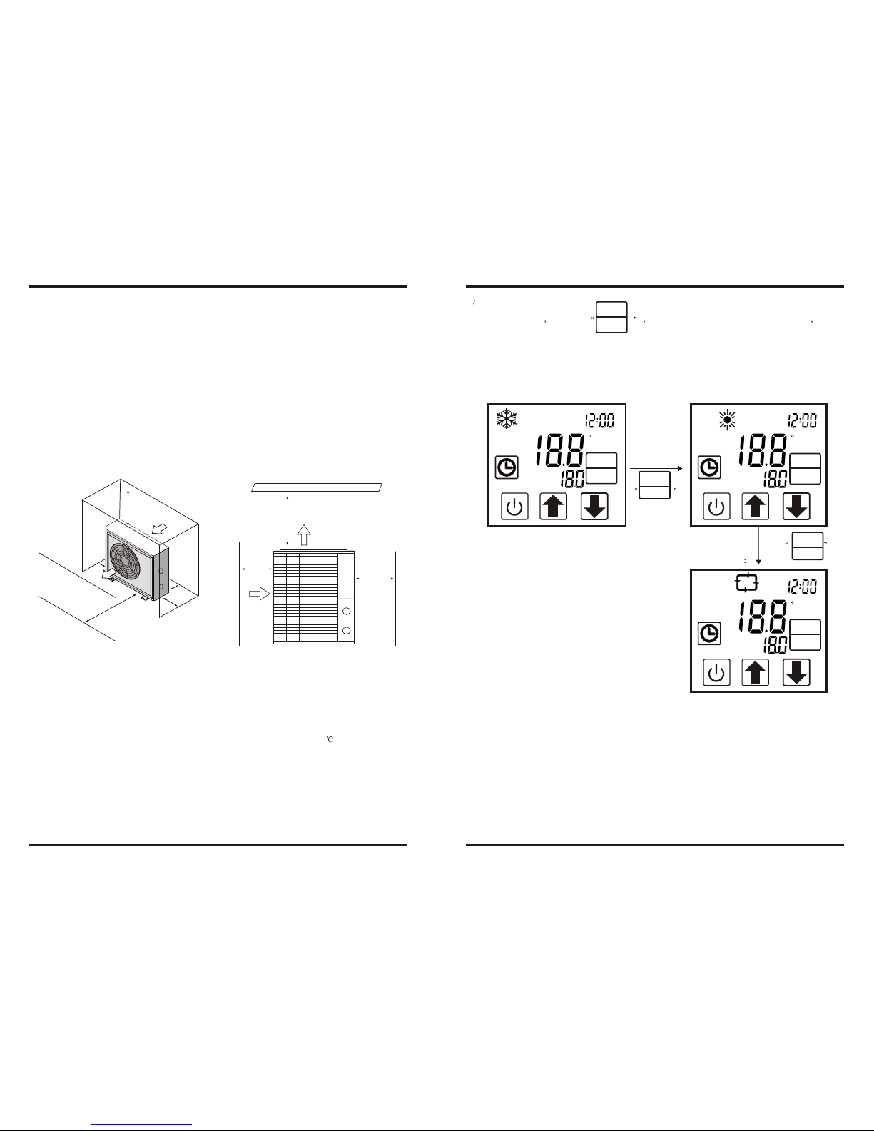
3.5 Swimming Pool Heat Pumps Electrical Wiring
NOTE: Althoughthe unit heatexchanger is electricallyisolated from therest of the unit, it
simply prevents theflow of electricityto or from the pool water. Grounding the unit is still
required to protectyou against shortcircuits inside theunit. Bonding is also required.
3.INSTALLATION AND CONNECTION
3.6 Initial startup of the Unit
NOTE- In orderfor the unitto heat the pool or spa, the filter pump must be running to
circulate water throughthe heat exchanger.
Start up Procedure- Afterinstallation is completed, you should follow these steps:
1. Turnon your filterpump. Check for water leaks and verify flow to and from the pool.
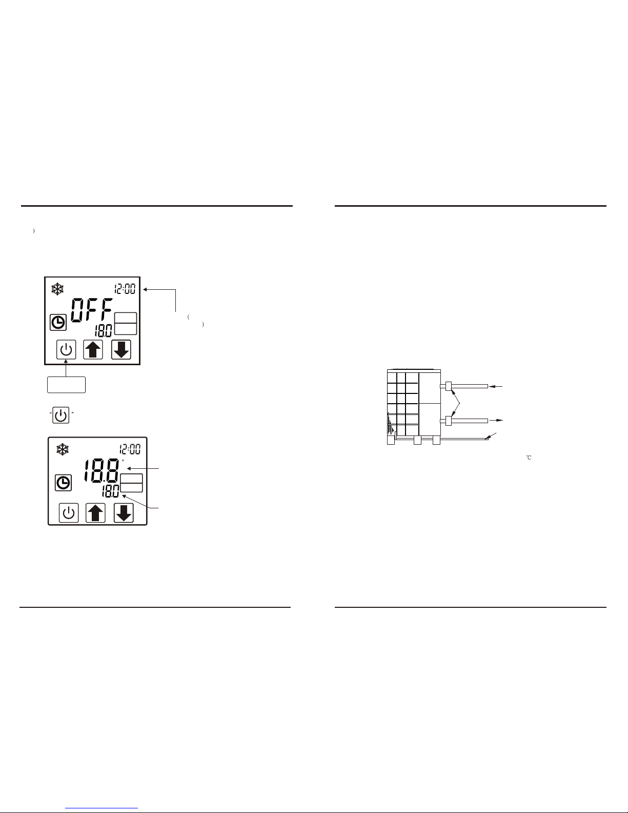
2. Turnon the electricalpower supply to the unit, then press the key ON/OFF of wire
controller, Itshould start in several seconds.
3. Afterrunning a fewminutes make sure the air leaving the top(side) of the unit is
cooler(Between 5-10 )
4. With theunit operating turn the filter pump off. The unit should also turn off automatically,
5. Allowthe unit andpool pump to run 24 hours per day until desired pool water emperature is
reached. When thewater-in temperature reach setting, The unit just shuts off. The unit will
now automatically restart(as long as your pool pump is running)when the pool temperature
drops more than2 below set temperature.
Time Delay- The unit is equipped with a 3 minute built-in solid state restart delay included to
protect control circuitcomponents and to eliminate restart cycling and contactor chatter.
This time delaywill automatically restart the unit approximately 3 minutes after each control
circuit interruption. Evena brief power interruption will activate the solid state 3 minute
restart delay andprevent the unit from starting until the 5 minute countdown is completed.
Power interruptions duringthe delay period will have no effect on the 3 minute countdown.
7
The unit hasa separate molded-in junction box with a standard electrical conduit nipple
already in place.Just remove the screws and the front panel, feed your supply lines in
through the conduitnipple and wire-nut the electric supply wires to the three connections
already in thejunction box (four connections if three phase). To complete electrical hookup,
connect Heat Pumpby electrical conduit, UF cable or other suitable means as specified (as
permitted by localelectrical authorities) to a dedicated AC power supply branch circuit
equipped with theproper circuit breaker, disconnect or time delay fuse protection.
Disconnect -A disconnect means (circuit breaker , fused or un-fused switch) should be
located within sightof and readily accessible from the unit, This is common practice on
commercial and residentialair conditioners and heat pumps. It prevents remotely-energizing
unattended equipment andpermits turning off power at the unit while the unit is being
serviced.
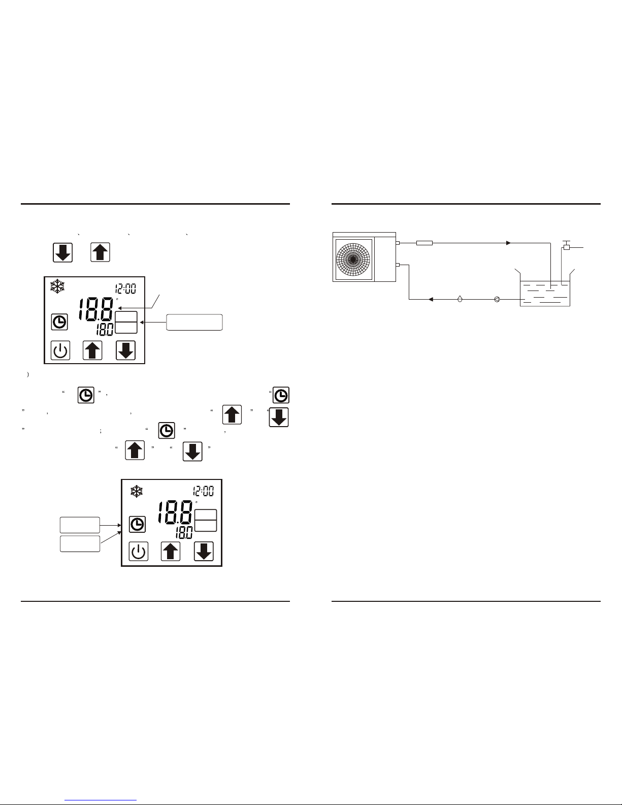
4.1 Function of the controller
User Interface and Usage as the following
Directions
TEMP
IN
SET
C
F
A
min
ON
OFF
TEMP
OUT
VOL
A
Closing screen if no action in two minutes
Refrigeration symbols,Displayed when refrigeration
(ON/OFF No LIMIT)
Heating Symbols,Displayed when heating
(ON/OFF NO LIMIT)
Automatic mode symbol(Temporarily useless)
Clock, timer functionkeys
Mode and tool button
ON/OFF key cancel key(cancel the current operation,
Back to the previous step of the operation)
Down key
Up key
8
4. USAGE AND OPERATION
MODE
SET
MODE
SET